Table of Contents
Advertisement
Advertisement
Table of Contents

Related Manuals for Robe COLORSPOT 170 AT


Summary of Contents for Robe COLORSPOT 170 AT
-
Page 3: Table Of Contents
COLORSPOT 170 AT Table of contents 1. Safety instructions ......................3 2.Operating determinations ....................4 3.Description of the device ....................5 4.Installation ........................6 4.1Fitting/Exchanging the lamp ..................6 4.2Lamp adjustment ......................6 4.3 Inserting/Exchanging the colours and rotating gobos..........7 4.4 Rigging ........................ -
Page 4: Safety Instructions
CAUTION! Keep this device away from rain and moisture! Unplug mains lead before opening the housing! FOR YOUR OWN SAFETY, PLEASE READ THIS USER MANUAL CAREFULLY BEFORE YOU INITIAL START - UP! 1. Safety instructions Caution ! Be careful with your operations.With a dangerous voltage you can suffer a dangerous electric shock when touching the wires This device has left our premises in absolutely perfect condition. -
Page 5: Operating Determinations
2.Operating determinations This device is a moving-head spot for creating decorative effects and was designed for indoor use only. This device is designed for professional use, e.g. on stages, in discotheques, theatres etc. Lighting effects are not designed for permanent operation. Consistent operation breaks will ensure that the device will serve you for a long time without defects. -
Page 6: Description Of The Device
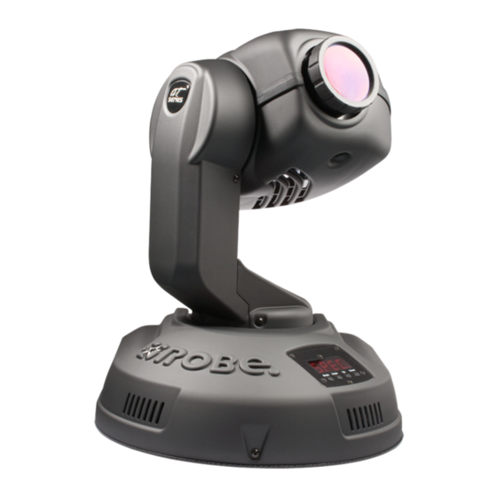
3.Description of the device 1 - Projector head 4 - Control panel 2 - Objective 5 - Base 3 - Arm Rear panel of the base 6 - DMX output 9 - Fuse holder 7 - DMX input 10 - Power cord 8 - Transport handle 11 - Power switch Control panel... -
Page 7: Installation
4.Installation 4.1Fitting/Exchanging the lamp DANGER ! Install the lamp with the device switched off only. Unplug from mains before ! Lamp socket assembly screws "X,Y,Z W" To insert the lamp (CDM-SA/T 150W/942): 1.Disconnect the fixture from power and allow it to cool. 2.Loosen the 4 screws „X, Y, Z,W”... -
Page 8: Inserting/Exchanging The Colours And Rotating Gobos
If the light is brighter around the edge than it is in the center, or if light output is low, the lamp is too far back in the reflector. „Push” the lamp out by turning the screws „A, B, C” counterclockwise 1/4-turn at a time the light is bright and evenly distributed. -
Page 9: Rigging
CAUTION! Never unscrew the screws of the rotating gobo as the ball bearing will otherwise be opened! 4.4 Rigging DANGER TO LIFE! Please consider the respective national norms during the installation! Theinstallation must only be carried out by an authorized dealer! The installation of the projector has to be built and constructed in a way that it can hold 10 times the weight for 1 hour without any harming deformation. - Page 10 The moving-head can be placed directly on the stage floor or rigged in any orientation on a truss without altering its operation characteristics . There are two possibility how to fix the COLORSPOT 170 AT on a truss via the Omega holders -see the drawings below.Use the rigging clamps (not included) with screws M12.
-
Page 11: Connection To The Mains
Fixation via the Omega holders 1. Screw the clamps (1) to the omega holders (4) through the hole in the holders. 2. Fasten the omega holders on the botton of the base by inserting both quick-lock fasteners (3) into the holes of the base and tighten fully clockwise. -
Page 12: Dmx- 512 Connection, Master/Slave Connection
4.6 DMX- 512 connection, master/slave connection Controller operation Master/slave operation Only use a stereo shielded cable and 3-pin XLR-plugs and connectors in order to connect the controller with the fixture or one fixture with another. Occupation of the XLR-connection: DMX - output DMX-input XLR mounting-socket: XLR mounting-plug:... -
Page 13: Dmx Protocol
5. DMX Protocol 16-bit 16-bit Mode 1 Mode 2 Value Function Type of control Channel Channel 0-255 Pan movement by 530° proportional Tilt 0-255 Tilt movement by 280° proportional Pan fine 0-255 Fine control of pan movement proportional Tilt fine 0-255 Fine control of tilt movement proportional... - Page 14 16-bit 16-bit Mode 1 Mode 2 Value Function Type of control Channel Channel 156-175 Gobo 4 proportional 176-195 Gobo 5 proportional 196-215 Gobo 6 proportional 216-235 Gobo 7 proportional 236-255 Gobo wheel rotation from slow to fast proportional Rotating gobo rotation 0-127 Gobo indexing proportional...
- Page 15 8-bit 16-bit Mode 3 Mode 4 Value Function Type of control Channel Channel 0-255 Pan movement by 530° proportional Tilt 0-255 Tilt movement by 280° proportional Pan fine 0-255 Fine control of pan movement proportional Tilt fine 0-255 Fine control of tilt movement proportional Speed of PAN/TILT movement Max.
- Page 16 8-bit 16-bit Mode 3 Mode 4 Value Function Type of control Channel Channel 96-235 Shaking gobos with variable speed 96-115 Gobo 1 proportional 116-135 Gobo 2 proportional 136-155 Gobo 3 proportional 156-175 Gobo 4 proportional 176-195 Gobo 5 proportional 196-215 Gobo 6 proportional 216-235...
-
Page 17: Controller Mode
COLORSPOT 170 AT will respond to the controller. If you set, for example, the address to channel 5, the COLORSPOT 170 AT will use the channel 5 to 16 for control (if the mode 1 is selected). -
Page 18: Stand - Alone Mode
Focus Motorized focus enables the beam to be focused anywhere on the stage. Shutter/Dimmer/Strobe The dimming (0-100%) is provided by the simple mechanical shutter unit. This unit may also be used for strobe effect (1 - 8 flashes per second). 7. -
Page 19: Functions Of The Control Panel
8. Functions of the control panel The control panel situated on the front side of the base offers several features. You can simply set the DMX address,master/slave mode, read the number of lamp or unit hours, run test, make a reset and also use many functions for setting and service purposes. -
Page 20: Slave Control
Press [ Up ] and [ Down ] buttons to select the desired option and press [ Enter ] to see the value or next submenu. Power On time -By this option you can read the total number of the operation hours since the COLORSPOT 170 AT has been fabricated. Press [ Enter ] or [ Mode ] to return to the menu. -
Page 21: Personality Options
- The number of the hours that the COLORSPOT 170 AT has been powered on since the counter was last reset.Press [Enter] or [Mode ] to return to the menu.In order to reset this counter to 0, you have to hold the [ Up ] and [ Down ]-button and press the [ Enter]-button. - Page 22 - Pan reverse This function allows you to invert the pan movement. Use the [ Up ] or [ Down ] buttons to select "On" if you wish this feature or "Off" if you don’t wish this feature and press [Enter ] to confirm or [ Mode ] to cancel and return to the menu.
- Page 23 Lamp presetting This function allows you to adjust the lamp settings: Lamp On after switching the fixture On This function enables to turn the lamp on automatically after switching the fixture on. Use the [ Up] and [Down] buttons to select "On" if you wish to turn the lamp on automatically after switching the fixture on or "Off"...
- Page 24 - Display -intensity With this function you can adjust the display intensity from 20% to 100% . Use the [Up ] or [Down ] buttons to select the level of the display intensity and press [ Enter ] to confirm or [ Mode ] to cancel and return to the menu.
-
Page 25: Switching On/Off The Lamp
- Default settings Press [ Enter ] to reset all fixture personalities (not the adjusting functions) to the default values. On the display will appear "rSt" meaning that the fixture makes the reset. See the table of personality setting and their default positions. -
Page 26: Test Sequences
This function allows you to run a special demo-test sequences without an external controller, which will show you some possibilities of using COLORSPOT 170 AT. Press [ Up ] or [ Down] keys to select the "Mod1" or "Mod2" sequences. The "Mod1" is suitable for projections on the wall, ceiling or ground without any head-movement, the "Mod2"... - Page 27 (playing is forced by the master). - Editing program This menu item allows you to select a program to edit or create.The COLORSPOT 170 AT has one built-in program ("tESt") and the 3 free programs,each up to 99 steps.
-
Page 28: Reset Function
8.8 Reset function Press [ Enter ] button to run a reset. This option enables the COLORSPOT 170 AT to index all effects (functions) and return to their standard positions. 8.9 Special functions Use the [ Up ] or [ Down ] buttons to browse through the special functions and select the one by pressing [ Enter ]-button. -
Page 29: Error And Information Messages
-- Fixture code The option contains identification code (1-9999) for the fixture, which is used for the master/slave operation. - Adjusting the default positions of the colour and gobo wheels By this function you can calibrate and adjust the colour and gobo wheels to their standard/right positions. Use the [Up] and [Down] buttons to browse through the adjusting menu - the display shows step by step these messages: "PAn, tilt,FPAn,FTilt,SPEd,Func,Colo,rGob,Grot,Foc, Stro,dimr,FCAL"... -
Page 30: Technical Specifications
PCB). The color-wheel is not located in the default position after the reset. r.G.Er. (Rotating gobo-wheel error) This message will appear after the reset of the fixture if the magnetic-indexing circuit malfunctions (sensor failed or magnet missing) or the stepping-motor is defective (or its driver circuit on the main PCB). - Page 31 Beampath: Colour-wheel - 10 dichroic-filters plus white - Colour-wheel with variable rotation speed - All colours are easily replaceable Rotating gobos-wheel - 3 metal gobos, 3 glass gobos and 1 dichroic gobo rotating in both directions at different speeds - Gobo indexing - Rotating gobo-wheel cont.
- Page 32 Channel Mode 1 (default) Mode 2 Mode 3 Mode 4 R.gobos R.gobos Focus No function Gobo rotation Gobo rotation Shutter,strobe No function Focus Focus Dimmer No function Shutter,strobe Shutter,strobe R.gobos Dimmer Dimmer Gobo rotation No function Focus Shutter,strobe Dimmer Pan/Tilt: -Pan movement range 530°...
-
Page 33: Maintenance And Cleaning
Accessories: gobo-set 8...........15050017 omega holder (2 pieces)........99010261 11. Maintenance and cleaning The operator has to make sure that safety-relating and machine-technical installations are inspected by an expert after every four years in the course of an acceptance test. The operator has to make sure that safety-relating and machine-technical installations are inspected by a skilled person once a year. -
Page 34: Appendix 1 - Menu Map
12. Appendix 1 - Menu map Menu Menu Menu Menu Menu Menu DESCRIPTION Level 1 Level 2 Level 3 Level 4 Level 5 Level 6 A001- dM.Ad. DMX addresss A497 d.Abl. Disable master/slave A001 MASt. Set fixture as a master MA.SL. - Page 35 Menu Menu Menu Menu Menu Menu DESCRIPTION Level 1 Level 2 Level 3 Level 4 Level 5 Level 6 Lamp power ON LAMP Lamp power OFF 0-255 Select pan value for demo running Mod.1 tilt 0-255 Select tilt value for demo running tESt Run demo without any head movement Run demo with head movement...
- Page 36 Menu Menu Menu Menu Menu Menu DESCRIPTION Level 1 Level 2 Level 3 Level 4 Level 5 Level 6 Fixture code Code 0-255 Select DMX value for pan position tilt 0-255 Select DMX value for tilt position F.Pan 0-255 Select DMX value for fine pan position F.tilt 0-255 Select DMX value for fine tilt position...
-
Page 37: Appendix 2 - Changing The Power Supply Settings
13. Appendix 2 - Changing the power supply settings Both the transformer and the ballast must be connected correctly for the local AC voltage and frequency. The wrong settings can cause poor performance or demage of the moving head.The factory settings are printed next to the power switch.
Need help?
Do you have a question about the COLORSPOT 170 AT and is the answer not in the manual?
Questions and answers