Table of Contents
Advertisement
Quick Links
Advertisement
Table of Contents

Subscribe to Our Youtube Channel
Related Manuals for Robe Anolis Eminere 1 MC


Summary of Contents for Robe Anolis Eminere 1 MC
- Page 1 QR code for user manual Version 1.2...
-
Page 2: Table Of Contents
Eminere MC Table of contents 1. Safety instructions ..............................3 2. Fixture exterior view ..............................5 3. Installation .................................. 5 3.1 Mounting the fixture ............................5 3.2 C-clamps installation ............................. 6 3.3 Connection to mains ............................. 7 3.4 The Booster box ..............................11 3.5 The Booster box installation .......................... -
Page 3: Safety Instructions
Eminere MC FOR YOUR OWN SAFETY, PLEASE READ THIS USER MANUAL CAREFULLY BEFORE POWERING OR INSTALLING YOUR Eminere MC ! Save it for future reference. This device has left our premises in absolutely perfect condition. In order to maintain this condition and to ensure safe operation, it is absolutely necessary for the user to follow the safety instructions and warnings written in this manual. - Page 4 Eminere MC Only operate the fixture after having checked that the housing is firmly closed and all screws are tightly fastened. The fixture becomes hot during operation. Allow the fixture to cool approximately 30 minutes prior to servicing or maintenance. Operate the fixture only after having familiarized yourself with its functions.
-
Page 5: Fixture Exterior View
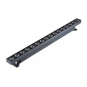
Eminere MC 2. Fixture exterior view 1. Transparent glass cover 2. LED module 3. Output connector 4. Input connector 5. Mounting brackets 6. Aluminium base 3. Installation 3.1 Mounting the fixture The Eminere MC can be arranged in any orientation on a flat, non-flammable surface by means of two mounting brackets (5), the LED module (2) can be tilted (+95°/-95°) to get access to mounting brackets (5). -
Page 6: C-Clamps Installation
Eminere MC 3.2 C-clamps installation 1. Remove the mounting bracket (5) from fixture housing by unscrewing two screws (6). 2. Screw the new mounting bracket (9) to the fixture housing by means of two screws (6). 3. Screw the clamp (7) to the mounting bracket by means of the bolt M12x30 (10) with nuts M12 (8). -
Page 7: Connection To Mains
Eminere MC 3.3 Connection to mains The unit must be installed by a qualified electrician in accordance with all national and local electrical and construction codes and regulations. This device falls under class one and must be grounded! The Eminere MC is equipped with auto-switching power supply that automatically adjusts to any 50/60Hz AC power source from 120-277 Volts. - Page 8 Eminere MC E-box Star E-box Lite...
- Page 9 Eminere MC Number of connected Emineres MC to one E-box output depends on a cable length, power voltage, type of Eminere MC and E-box and operation mode. The tables below state max. theoretical number of Emineres MC connected to the one LED output of the E-box without Booster boxes.
- Page 10 Eminere MC EMINERE 4 MC Voltage Cable length * 120V 190V 230V 277V 10 m 20 m 30 m 50 m 70 m 100 m 200 m * Cable length is a total cable length between E-box and last connected Eminere MC. Example: Total cable length=L1+L2+L3 Notice for the E-box Star: The tables above state max.
-
Page 11: The Booster Box
Eminere MC 3.4 The Booster box To compensate a voltage drop in large installation, the Booster boxes have to be connected in the chain of Emineres MC at every LED output of the E-box. The following tables give numbers of Emineres MC after which the Booster box has to be installed in the chain of Emineres MC (at one LED output of the E-box). - Page 12 Eminere MC EMINERE 3 Max. number of Emineres 3 MC= 64 Voltage Cable 120V 190V 230V 277V length 10 m 28,56 20 m 28,56 30 m 19,38,57 50 m 12,24,36,48,60 29,58 70 m 8,16,24,32,40,48,56 21,42,63 31.62 100 m 6,12,18,24,30,36,42,48,54, 15,30,45,60 21,42,63 31,62 200 m...
-
Page 13: The Booster Box Installation
Eminere MC 3.5 The Booster box installation ALWAYS DISCONNECT THE EMINERES MC FROM MAINS BEFORE CONNECTING/DISCONNECTING THE BOOSTER BOX. The Booster box falls under protection class I. Therefore, every Booster box has to be connected to a mains socket outlet with a protective earthing connection. 1.Unscrew the four screws (1) from the cover (2) on the Booster box to get access to the terminal block (3) and two mounting holes of diameter of 4.6 mm (4). - Page 14 Eminere MC Cable gland M20 MS: The cable gland M20 MS with a standard seal serves for a cable of diameter of 7-13mm, for smaller diameter of cable (4-8mm) you have to remove the original seal from the cable gland M20 and use the enclosed reducing seal instead of it.
-
Page 15: Jumper Cable Assembling
Eminere MC 3.6 Jumper cable assembling 1. Dismantle the connector and slide its parts onto the cable (6). Use the seal with inner diameter of 14.5 mm for the Anolis cable (P/N 13053138 or P/N 13053139). The seal with inner diameter of 14.5 mm serves for cable of diameter 10-14.5mm. The seal with inner diameter of 10 mm serves for cable of diameter 8-10mm. - Page 16 Eminere MC US version 3. Put parts of the connector on the cable (6) and connect wires to the connector. First connect power wires (L,N, Earth) and after that data wires (D+, D-, 0V). Avoid excessive torsion of data wires! CE version Male Female...
- Page 17 Eminere MC 4. After connecting wires to the connector, tighten the three data wires (D+,D-, 0V) by means of the cable binder (7). 6. Screw the clamp ring (3) to the connector (1), insert the seal (4) to the clamp ring (3) and tighten the sealing nut (5) enough.
-
Page 18: Software Update
Emineres MC including the E-box: 1. Set the E-box to the Standard mode and switch it off/on. Only E-box will be shown in the ROBE Uploader. You have to use the file EminereEbox.lib in the ROBE Uploader for software update of the E-box and connected LED modules. -
Page 19: Technical Specifications
Eminere MC 5. Technical specifications Power supply • Electronic auto-ranging • Input voltage: 120 - 277V AC, 50/60 Hz • Power consumption: Eminere 1 MC: 25W Eminere 2 MC: 45W Eminere 3 MC: 65W Eminere 4 MC: 85W • Inrush current: Eminere 1 MC: <70A/250µs Eminere 2 MC: <70A/250µs Eminere 3 MC: <100A/200µs... - Page 20 Eminere MC Mounting method • Via two L-shape brackets • LED module “tilt” adjustment range: -95°/+95° Sizes • Eminere 1 MC (300mm / 1ft) • Eminere 2 MC (600mm / 2ft) • Eminere 3 MC (900mm / 3ft) • Eminere 4 MC (1200mm / 4ft) Housing •...
- Page 21 Eminere MC Dimensions (All dimensions in mm [inch]) • C-Clamp...
- Page 22 Eminere MC • Booster box Included items • 1 x Eminere • 1 x User manual Optional accessories CE Leader Cables FF: Leader Cable FF 2m (P/N 13053438) Leader Cable FF 5m (P/N 13053440) Leader Cable FF 10m (P/N 13053436) Leader Cable FF 25m (P/N 13053437) Leader Cable FF 50m (P/N 13053439)
- Page 23 Eminere MC US Leader Cables FF: Leader Cable FF 2m (P/N 13053433) Leader Cable FF 5m (P/N 13053435) Leader Cable FF 10m (P/N 13053431) Leader Cable FF 25m (P/N 13053432) Leader Cable FF 50m (P/N 13053434) Jumper Cables FF/FM: Jumper Cable FF/FM 0.25m (P/N 13053422) Jumper Cable FF/FM 0.5m (P/N 13053423) Jumper Cable FF/FM 1m (P/N 13053425) Jumper Cable FF/FM 2m (P/N 13053427)
-
Page 24: Cleaning And Maintenance
13/09/2023 Jumper and leader cables numbers changed Specifications are subject to change without notice. September 13, 2023 Copyright © 2019-2023 Robe Lighting - All rights reserved Made in CZECH REPUBLIC by ROBE LIGHTING s.r.o. Palackeho 416/20 CZ 75701 Valasske Mezirici... - Page 25 DMX protocol DMX protocol for: Eminere 1/2/3/4; Eminere Side 1/2/3/4; Eminere Inground 2/4; Eminere Remote 1/2/3/4; UVinere 2/4; UVinere Remote 1/2/4 Version: 3.2 (23 modes in total), software version 3.0 and higher Mode/Channels in all Mode 1: RGBW(A)-8bit, Mode 2: RGB 8-bit, Mode 3: full RGBW(A) 8-10 Mode 4: White-full control, Mode 5: Reduced RGBW(A) Mode 6- Reduced RGBW(A)+white control...
- Page 26 DMX protocol Mode/channels Type of Function Value control White 1800 K step White 2700 K step White 3200 K step White 4200 K step 9-10 White 5600 K step 11-12 White 6500 K step step Blue (Blue=full, Red+Green+White/Amber=0) 14-23 Red=0, Green->up,Blue =full, White/Amber=0 proportional step Cyan (Red=0, Green=full, Blue =full, White/Amber=0)
- Page 27 Random strobe-effect from slow to fast 192-223 proportional Shutter open 224-255 step Dimmer 0-255 Light intensity coarse (0-100%) proportional Dimmer Fine 0-255 Light intensity fine proportional Copyright © 2022-2023 Robe Lighting s.r.o. - All rights reserved All Specifications subject to change without notice Page 3...
- Page 28 Dimmer 0 - 255 Light intensity coarse (0 - 100%) proportional Dimmer Fine 0 - 255 Light intensity fine proportional Copyright © 2022-2023 Robe Lighting s.r.o. - All rights reserved All Specifications subject to change without notice Page 1...
- Page 29 DMX protocol DMX protocol for: Eminere 1/2/3/4; Eminere Side 1/2/3/4; Eminere Inground 2/4; Eminere Remote 1/2/3/4; Version: 3.2 (23 modes in total) Mode/Channels in all Mode 17: RGBW(A) pixels, Mode 18: RGB pixels, Mode 19: TW pixels, 21-23 Mode 20: PW dimmer pixels Reserved Pixel modes Mode/channels...
- Page 30 Dimmer 4 0 - 255 Light intensity coarse (0 - 100%) proportional Dimmer Fine 4 0 - 255 Light intensity fine proportional Copyright © 2022-2023 Robe Lighting s.r.o. - All rights reserved All Specifications subject to change without notice Page 2...
Need help?
Do you have a question about the Anolis Eminere 1 MC and is the answer not in the manual?
Questions and answers