Advertisement
Quick Links
PN# 500-18800
Rev. A.1, 8/01
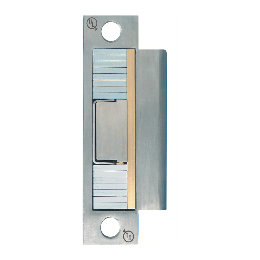
SECURITRON MODEL MUNL-12, MUNL-24 MORTISE UNLATCH
1. DESCRIPTION
Securitron's Mortise UnLatch is a revolutionary new type of electric strike which eliminates the
necessity to perform a routing operation on the door frame for installation. The motor
driven Mortise UnLatch also presents a fully concealed appearance on the door which not
only enhances architectural appeal but improves security over a conventional electric strike as
an intruder is less able to determine the type of security device present on the door. The
Mortise UnLatch functions with all North American mortise locks and includes a latch
status output which reports when the door is in latched (secure) condition or is open.
Product Specifications are: Input Voltages: 12 VDC (MUNL-12), +20%, -10%. 24 VDC
(MUNL-24), +20%, -10%. Current: At rest: 40 mA (either voltage). When operating- 4 Amp
input surge @ 12 VDC; 2 Amp input surge @24 VDC for 100 milliseconds and 600 mA @ 12
VDC or 300 mA @ 24 VDC during motor movement. Operating Temperature: -10° to 125° F.
1.25
3.50
2. PHYSICAL INSTALLATION
2.1 SURVEY
The installer must first be sure that the latch is of the mortise type
(see the drawing to the right.) A mortise lock (or latch) includes a
square shaped springlatch and a "pin" called the deadlatch pin or
guard bolt which may be positioned either above or below the
springlatch. Most mortise panic bar latches are also perfectly
compatible with the MUNL. Note, however, that if the mortise lock
assembly includes a dead bolt, the dead bolt will not be operable
The most common alternate type of latch in use in North America is
called cylindrical, tubular or bored. The standard UnLatch (model
numbers UNL-12 and UNL-24) is designed for this alternate type of
latch. Securitron does not offer an UnLatch solution for a rim latch
(rim latches are on the surface of the door rather than being mortised
into the middle of the door).
Copyright, 2001, all rights reserved • Securitron Magnalock Corp., 550 Vista Blvd., Sparks NV 89434, USA
Tel: (775) 355-5625 • (800) MAGLOCK • Fax: (775) 355-5636 • Website: www.securitron.com
An ASSA ABLOY Group company
INSTALLATION AND OPERATING INSTRUCTIONS
FIG 1: MORTISE UNLATCH DIMENSIONS (INCHES)
1.88
4.88
1.25
3.38
RECOMMENDED TOOLS
MEDIUM + SMALL PHILLIPS DRIVER
MEDIUM SLOTTED DRIVER
CHISEL, 5/64 ALLEN WRENCH
WIRE CUTTER/STRIPPER
VOLT/OHM METER
CRIMP CONNECTORS
CRIMP PLIERS
SPRINGLATCH
PLUNGER
DEADLATCH
FINGERS
Springlatch
Deadlatch Pin
Page 1
Advertisement

Related Manuals for Assa Abloy Door Lock


Summary of Contents for Assa Abloy Door Lock
- Page 1 Copyright, 2001, all rights reserved • Securitron Magnalock Corp., 550 Vista Blvd., Sparks NV 89434, USA Tel: (775) 355-5625 • (800) MAGLOCK • Fax: (775) 355-5636 • Website: www.securitron.com An ASSA ABLOY Group company 1.25 4.88 3.38...
- Page 2 Rev. A.1, 8/01 Page- 2 2.2 HOLLOW METAL (STEEL) FRAME MOUNTING Remove the existing ANSI 4 7/8” strike plate (it will be discarded) and experimentally try to fit the Mortise UnLatch in the resulting cavity. In some cases the cavity will be large enough to accommodate the Mortise UnLatch and you will have nothing to do but pull the wires up the hollow door frame and screw the Mortise UnLatch into place.
- Page 3 Rev. A.1, 8/01 lines and knowledge of the gap between the springlatch and deadlatch pin are used to determine the vertical position of the springlatch plunger. When this gap is greater than ¼”, best reliability is obtained when the springlatch plunger position is centered on the springlatch. When the gap is smaller than ¼”, however, simply centering the springlatch plunger risks positioning the deadlatch pin too close to the springlatch plunger so the procedure is to position the edge of the springlatch plunger midway between the springlatch and deadlatch pin.
- Page 4 Rev. A.1, 8/01 FIG. 3: ADJUSTING SPRINGLATCH POSITION Perform these adjustments with the unit on a flat surface and be careful not to lose the small screws Remove Small Cover (Small Phillips Driver) Remove "U" Shield (5/64" Allen Wrench) Be especially careful not to let a screw or any other object fall inside the housing as it can jam the Mortise UnLatch Push in Springlatch plunger and hold it...
-
Page 5: Operation
Rev. A.1, 8/01 If the amount of slack or rattling is less than 1/16-1/8”, you have a “tight” door and the ability of the door to close and latch reliably is in question. To adjust for this, first check to see if the stop has “silencers”... - Page 6 Rev. A.1, 8/01 FIG 5: MORTISE UNLATCH SIDE VIEW IN REST (SECURE) POSITION SPRINGLATCH PLUNGER IN THE REST (SECURE) POSITION, THE SPRINGLATCH IS ALLOWED TO COME OUT BY THE SPRINGLATCH PLUNGER THEREBY SECURING THE DOOR. THE DEADLATCH FINGERS, HOWEVER, PUSH IN THE DEADLATCH PIN WHICH "FREEZES"...
-
Page 7: General Electrical Characteristics
Rev. A.1, 8/01 Note that if the door is heavily pre-loaded (by someone trying to pull it open before the Mortise UnLatch has released it for example), the Mortise UnLatch may not possess enough power to release the door. This is termed a stall condition for the motor. When a motor is stalled for a period of time, it can be damaged by heat build up as motors draw heavy current when they’re not permitted to move. -
Page 8: Wire Gauge Sizing
Rev. A.1, 8/01 UnLatches, the extra current capability will always be there as each unit will operate at different times so each can draw extra current from the power supply when needed. If you are using a smaller capacity power source, you may be satisfied with the operation of the Mortise UnLatch since the reduction in torque is only noticeable when the door is pre- loaded. - Page 9 Rev. A.1, 8/01 Page- 9 MAGNACARE LIMITED LIFETIME WARRANTY SECURITRON MAGNALOCK CORPORATION warrants that it will replace at customer’s request, at any time for any reason, products manufactured and branded by SECURITRON. SECURITRON will use its best efforts to ship a replacement product by next day air freight at no cost to the customer within 24 hours of SECURITRON’s receipt of the product from customer.
-
Page 10: Appendix A: Troubleshooting
Rev. A.1, 8/01 PROBLEM -- Unit will not operate when trigger wire is connected to +V. On a new installation, make sure that DC power (12 or 24 volts depending on the model) is connected to the red and black wires with correct polarity. When this is confirmed, note that the Mortise UnLatch will never operate unless the springlatch plunger is pushed in by the springlatch (see Section 3.3). - Page 11 Rev. A.1, 8/01 Page- ii TEMPLATE FOR CHISELING OUT A WOOD FRAME 1 1/4"...
Need help?
Do you have a question about the Door Lock and is the answer not in the manual?
Questions and answers