Table of Contents
Advertisement
Quick Links
DL100 Wireless Deadlatch
Installation Instructions
Frame and Door
Preparation
PREPARE the door and frame
1
per Diagrams 2A-5.
BACKSET for the mortise cylinder
2
hole is found on Page 2.
DIAGRAM 1: Door & Frame Gap
For optimal lock performance,
the gap between the door and
frame must meet industry
standard of 1/8".
.125"
[3.2 mm]
DIAGRAM 2A: Frame Preparation
FRAME
1.25"
[31.8 mm]
2.91"
[74 mm]
2X .87"
[22 mm]
.435"
[11 mm]
DIAGRAM 3: Door Preparation:
Mounting holes for Lock and DPS
BACK OF STILE
6.38"
[162.1 mm]
2X
#10-32
UNF-2B
DPS Location
Recommended
Below Lock
7.08"
[179.8 mm]
SURFACE
MOUNTED
STRIKE PLATE
1.13"
[28.6 mm]
1.02"
[25.9 mm]
.90"
[22.9 mm]
4X #4 X 1/4"
UNDERCUT FLAT
HEAD SCREWS
DIAGRAM 4: Door Preparation:
Mounting holes for Paddle (Sold Separately)
Mounting
Holes if using
4591 Paddle
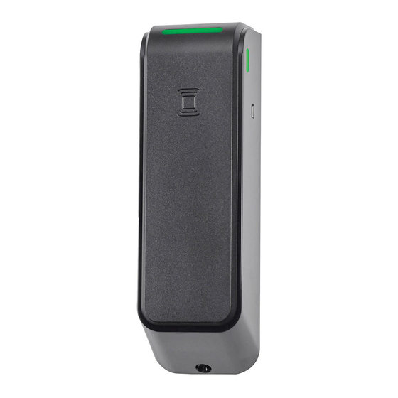
DIAGRAM 2B: Door Preparation: Mounting holes for Reader*
DOOR
Ø 3/8"
[9.5mm]
Reader
Harness
CYLINDER
1.44"
Ø 1.25"
[36.6 mm]
[31.8 mm]
*NOTE: Center Reader horizontally on Door Stile.
Horizontal placement is Door Stile dependent.
DIAGRAM 5: Door Preparation:
Lock Cut-Out to Backset/Cylinder
7" MAX
[177.8 mm MAX]
Backset "A"
See Diagrams
6A and 6B
1.6"
[40.6 mm]
6.885" +.005"/-.000"
[174.88 mm +.38mm/ -.00 mm]
4X R .156"
[3.96 mm] TYP.
1.010" +.015"/-.000"
[25.7 mm +.4 mm/ -.00 mm]
1 of 8
Advertisement
Table of Contents

Related Manuals for Assa Abloy Adams Rite DL100


Summary of Contents for Assa Abloy Adams Rite DL100
- Page 1 DL100 Wireless Deadlatch Installation Instructions Frame and Door DIAGRAM 2B: Door Preparation: Mounting holes for Reader* DOOR Preparation Ø 3/8" [9.5mm] DIAGRAM 2A: Frame Preparation Reader PREPARE the door and frame Harness per Diagrams 2A-5. BACKSET for the mortise cylinder hole is found on Page 2.
- Page 2 Frame and Door Prep Continued HOW BACKSET DIAGRAM 6A: Lock Dimensions DIAGRAM 6B: Door Stiles DIAGRAM 6C: Mortise Cylinder Cam. IS MEASURED: Turning Key / Handle / Paddle DOES NOT DIM “B” CYLINDER C L pull Main Latch Assy. .63" 1"...
-
Page 3: Reader Mounting
Reader Mounting DIAGRAM 8: Backplate drill holes DIAGRAM 9: Batteries into cover PERFORM a site survey to ensure the opening is appropriate for the DL100 installation and the BACKPLATE RF capability is optimum. Reader cable READER exit hole CONFIRM center of cylinder prep to Install 2X AA bottom of reader backplate is not lithium batteries... - Page 4 Lock Prep for Traditional DIAGRAM 13A: DIAGRAM 13B: Mounting Installations DEPTH BACK of DIM. DEPTH STILE WALL DIM. MEASURE the depth from the back of the INSIDE of stile to the inside wall, see Diagram 13A. STILE WALL MATCH THE DEPTH dimension from face of Mounting Plate to the Tube spacers.
-
Page 5: Wiring Schematic
Bevel Adjustment ROTATE bevel tab to desired hand position, see Diagram 15. Bevel adjustment allows flat faceplate to Rotate Bevel Tabs to RHR sit flush with beveled door stile. Radius Position for beveled door stiles and Flat Faceplates are included. DIAGRAM 15: Outline of Outline of... - Page 6 Installation Connections DIAGRAM 17: READER CONNECT Reader to lock. CONNECT DPS (door position sensor) to connector with DOOR STILE FRONT of CAM white wires on lock (use CYLINDER shorting plug if no DPS). CONNECT REX (request to exit) to connector with black wires on lock.
-
Page 7: Led Codes
Aperio Hub Specifications Approvals Internal Antenna Receiver Sensitivity CE, ETL, FCC, IC, C-Tick 2 cross polarized dipoles -100dBm 20% PER Safety & Emissions External Antenna Wireless Transmit Power FCC 47CFR Part 15 subpart B and subpart C; (Part No. EXT-10-ANT) One reverse polarity SMA 10 d Bm/MHz IC RSS-210 EN ETSI 301 489-17 v2.1.1;... -
Page 8: Product Specifications
Patent pending and/or patent www.assaabloydss.com/patents techsupport.adamsrite@assaabloy.com Copyright © 2022, Hanchett Entry Systems, Inc., an ASSA ABLOY Group company. 10027 S. 51st Street, Ste. 102 Phoenix, AZ 85044 USA All rights reserved. Reproduction in whole or in part without the express written permission of Hanchett Entry Systems, Inc.
Need help?
Do you have a question about the Adams Rite DL100 and is the answer not in the manual?
Questions and answers