Sign In
Upload
Manuals
Brands
Omron Manuals
Inverter
SX-F
Omron SX-F Manuals
Manuals and User Guides for Omron SX-F. We have
1
Omron SX-F manual available for free PDF download: Instruction Manual
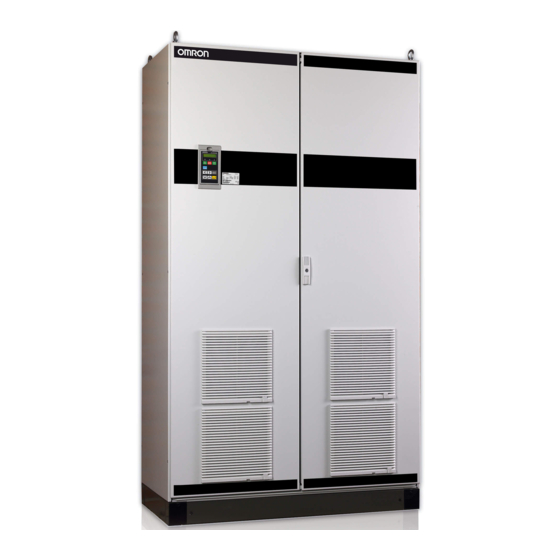
Omron SX-F Instruction Manual (316 pages)
High power Direct Torque Control Inverters
Brand:
Omron
| Category:
Inverter
| Size: 4.88 MB
Table of Contents
Safety Instructions
6
Precautions Severity
6
Warnings and Cautions
6
Table of Contents
9
Section 1
15
Introduction
15
Delivery and Unpacking
15
Using the Instruction Manual
15
Ordering Codes
16
Standards
17
Product Standard for EMC
17
Dismantling and Scrapping
18
Glossary
19
Abbreviations and Symbols
19
Definitions
19
Section 2
21
Mounting
21
Lifting Instructions
21
Stand-Alone Units
24
Cooling
24
Mounting Schemes
25
Cabinet Mounting
29
Cooling
29
Recommended Free Space in Front of Cabinet
29
Mounting Schemes
30
Section 3
33
Installation
33
Before Installation
33
Cable Connections
33
Mains Cables
33
Motor Cables
35
Connect Motor and Mains Cables
39
Connection of Mains and Motor Cables on IP20 Modules
41
Cable Specifications
42
Stripping Lengths
42
Dimension of Cables and Fuses
42
Tightening Torque for Mains and Motor Cables
42
Thermal Protection on the Motor
43
Motors in Parallel
43
Section 4
45
Getting Started
45
Connect the Mains and Motor Cables
45
Mains Cables
45
Motor Cables
45
Using the Function Keys
46
Remote Control
46
Connect Control Cables
46
Switch on the Mains
47
Set the Motor Data
47
Run the VSD
48
Local Control
48
Switch on the Mains
48
Select Manual Control
48
Set the Motor Data
48
Enter a Reference Value
48
Section 5
49
Control Connections
49
Control Board
49
Terminal Connections
50
Inputs Configuration
51
With the Switches
51
Connection Example
52
Connecting the Control Signals
53
Cables
53
Types of Control Signals
55
Screening
56
Single-Ended or Double-Ended Connection
56
Current Signals ((0)4-20 Ma)
56
Twisted Cables
57
Connecting Options
57
Section 6
59
Applications
59
Cranes
59
Crushers
59
Mills
59
Mixers
60
Section 7
61
Main Features
61
Parameter Sets
61
One Motor and One Parameter Set
63
One Motor and Two Parameter Sets
63
Two Motors and Two Parameter Sets
63
Autoreset at Trip
63
Reference Priority
64
Preset References
64
Remote Control Functions
65
Performing an Identification Run
68
Using the Control Panel Memory
69
Load Monitor and Process Protection [400]
70
Load Monitor [410]
70
Emc
73
EMC Standards
73
Section 8
73
Section 9
75
Operation Via the Control Panel
75
General
75
The Control Panel
75
The Display
75
Indications on the Display
77
LED Indicators
77
Control Keys
77
The Toggle and Loc/Rem Key
78
Function Keys
80
The Menu Structure
81
The Main Menu
82
Programming During Operation
82
Editing Values in a Menu
83
Copy Current Parameter to All Sets
83
Programming Example
83
Section 10
85
Serial Communication
85
Modbus RTU
85
Parameter Sets
86
Motor Data
86
Start and Stop Commands
87
Reference Signal
87
Process Value
87
Description of the Eint Formats
88
Section 11
91
Functional Description
91
Preferred View [100]
91
1St Line [110]
92
2Nd Line [120]
92
Main Setup [200]
92
Operation [210]
93
Remote Signal Level/Edge [21A]
98
Mains Supply Voltage [21B]
99
Motor Data [220]
99
Motor Protection [230]
106
Parameter Set Handling [240]
110
Trip Autoreset/Trip Conditions [250]
114
Serial Communication [260]
126
Process and Application Parameters [300]
131
Set/View Reference Value [310]
131
Process Settings [320]
132
Start/Stop Settings [330]
139
Mechanical Brake Control
146
Speed [340]
150
Torques [350]
155
Preset References [360]
158
PI Speed Control [370]
160
PID Process Control [380]
162
11-3-10Crane Option [3A0]
179
Load Monitor and Process Protection [400]
185
Load Monitor [410]
185
Process Protection [420]
192
I/Os and Virtual Connections [500]
195
Analogue Inputs [510]
195
Digital Inputs [520]
206
Analogue Outputs [530]
209
Digital Outputs [540]
215
Relays [550]
218
Virtual Connections [560]
221
Logical Functions and Timers [600]
223
Comparators [610]
223
Logic Output y [620]
238
Logic Output Z [630]
241
Timer1 [640]
243
Timer2 [650]
246
View Operation/Status [700]
249
Operation [710]
249
Status [720]
253
Stored Values [730]
258
View Trip Log [800]
261
Trip Message Log [810]
261
Trip Messages [820] - [890]
262
Reset Trip Log [8A0]
263
System Data [900]
264
VSD Data [920]
264
Section 12
267
Troubleshooting, Diagnoses and Maintenance
267
Trips, Warnings and Limits
267
Trip Conditions, Causes and Remedial Action
269
Technically Qualified Personnel
269
Opening the Variable Speed Drive
269
Precautions to Take with a Connected Motor
269
Autoreset Trip
270
Maintenance
272
Section 13
275
Options
275
Options for the Control Panel
275
CX-Drive Software
275
Brake Chopper
276
I/O Board
278
Encoder
278
Ptc/Pt100
278
Crane Option Board
278
Serial Communication and Fieldbus
278
Standby Supply Board Option
279
13-10Safe Stop Option
281
13-11Output Coils
283
13-12Liquid Cooling
283
Section 14
285
Technical Data
285
Electrical Specifications Related to Model
285
General Electrical Specifications
286
Operation at Higher Temperatures
288
Dimensions and Weights
289
Environmental Conditions
289
Fuses, Cable Cross-Sections and Glands
290
According IEC Ratings
290
Fuses and Cable Dimensions According NEMA Ratings
292
Control Signals
294
Section 15
295
Menu List
295
Index
311
Advertisement
Advertisement
Related Products
Omron Sysdrive RX Series
Omron SYSDRIVE MX Series
Omron SYSDRIVE JX Series
Omron SPINOGY 3G3MX2
Omron SYSDRIVE RV Series
Omron AnyFeeder SXM100
Omron AnyFeeder SXM140
Omron AnyFeeder SX240
Omron AnyFeeder SX340
Omron SRT1 Series
Omron Categories
Blood Pressure Monitor
Controller
Accessories
Switch
Inverter
More Omron Manuals
Login
Sign In
OR
Sign in with Facebook
Sign in with Google
Upload manual
Upload from disk
Upload from URL