Sign In
Upload
Manuals
Brands
Mitsubishi Manuals
Inverter Drive
FR - S500
Mitsubishi FR - S500 Manuals
Manuals and User Guides for Mitsubishi FR - S500. We have
3
Mitsubishi FR - S500 manuals available for free PDF download: Instruction Manual, Manual
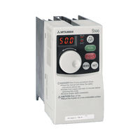
Mitsubishi FR - S500 Instruction Manual (191 pages)
Transistorized Inverter
Brand:
Mitsubishi
| Category:
Inverter
| Size: 2.34 MB
Table of Contents
Table of Contents
6
Wiring
10
Japanese Version
11
Terminal Connection Diagram
11
Layout and Wiring of Main Circuit Terminals
12
North America Version
13
Terminal Connection Diagram
13
Layout and Wiring of Main Circuit Terminals
14
European Version
16
Terminal Connection Diagram
16
Layout and Wiring of Main Circuit Terminals
17
Description of I/O Terminal Specification
18
Description of I/O Terminal Specifications
18
Main Circuit
18
Control Circuit
18
How to Use the Main Circuit Terminals
20
Cables, Wiring Lengths, Crimping Terminals, Etc
20
Wiring Instructions
21
Peripheral Devices
22
Leakage Current and Installation of Earth Leakage Circuit Breaker
24
Power-Off and Magnetic Contactor (MC)
26
Regarding the Installation of the Power Factor Improving Reactor
27
Regarding Noise and the Installation of a Noise Filter
27
Grounding Precautions
28
Regarding Power Harmonics
29
Japanese Power Harmonic Suppression Guideline
29
How to Use the Control Circuit Terminals
33
Terminal Block Layout
33
Wiring Instructions
33
Changing the Control Logic
34
Input Terminals
37
Run (Start) and Stop (STF, STR, STOP)
37
Connection of Frequency Setting Potentiometer and Output Frequency Meter (10, 2, 5, 4, AU)
40
External Frequency Selection (REX, RH, RM, RL)
41
Indicator Connection and Adjustment
43
Control Circuit Common Terminals (SD, 5, SE)
46
Signal Inputs by Contactless Switches
46
How to Use the Input Signals (Assigned Terminals RL, RM, RH, STR)
47
Multi-Speed Setting (RL, RM, RH, REX Signals): Setting "0
47
Remote Setting (RL, RM, RH Signals): Setting "0, 1, 2
47
Second Function Selection (RT Signal): Setting "3
47
Current Input Selection "AU Signal": Setting "4
47
Start Self-Holding Selection (STOP Signal): Setting "5
47
Output Shut-Off (MRS Signal): Setting "6
48
External Thermal Relay Input: Setting "7
48
Jog Operation (JOG Signal): Setting "9
49
Reset Signal: Setting "10
49
PID Control Valid Terminal: Setting "14
50
PU Operation/External Operation Switching: Setting "16
50
Handling of the RS-485 Connector (Type with RS-485 Communication Function)
50
Design Information
53
Functions
54
Function (Parameter) List
55
List of Parameters Classified by Purpose of Use
65
Explanation of Functions (Parameters)
67
Torque Boost
67
Maximum and Minimum Frequency
68
Base Frequency, Base Frequency Voltage
68
Multi-Speed Operation to to
70
Acceleration/Deceleration Time
71
Electronic Overcurrent Protection
73
DC Injection Brake
73
Starting Frequency
74
Load Pattern Selection
75
Jog Frequency
76
RUN Key Rotation Direction Selection
76
Stall Prevention Function and Current Limit Function
77
Stall Prevention
78
Acceleration/Deceleration Pattern
80
Extended Function Display Selection
81
Frequency Jump to
81
Speed Display
82
Biases and Gains of the Frequency Setting Voltage (Current)
83
Start-Time Ground Fault Detection Selection
87
Output Terminal Function Parameters
87
Up-To-Frequency Sensitivity
87
Output Frequency Detection
88
Current Detection Function Parameters
89
Output Current Detection Functions
89
Zero Current Detection
90
Display Function Parameters
91
Monitor Display
91
Setting Dial Function Selection
92
Monitoring Reference
93
Restart Operation Parameters
93
Restart Setting
93
Additional Function Parameters
95
Remote Setting Function Selection
95
Terminal Function Selection Parameters
97
Input Terminal Function Selection
97
Output Terminal Function Selection
99
Operation Selection Function Parameters
100
Retry Function
100
PWM Carrier Frequency
101
Applied Motor
102
Voltage Input Selection
102
Input Filter Time Constant
103
Reset Selection/Pu Stop Selection
103
Cooling Fan Operation Selection
105
Parameter Write Inhibit Selection
106
Reverse Rotation Prevention Selection
107
Operation Mode Selection
107
PID Control to
110
Auxiliary Function Parameters
118
Slip Compensation
118
Automatic Torque Boost Selection
118
Operating Conditions
119
Motor Primary Resistance
120
Calibration Parameters
120
Meter (Frequency Meter) Calibration (Japanese Version)
120
Meter (Frequency Meter) Calibration (NA and EC Version)
122
Clear Parameters
124
Parameter Clear
124
Alarm History Clear
124
Communication Parameters (Only for the Type Having the RS-485 Communication Function)
125
Communication Settings to
127
Setting Items and Set Data
135
Error Code List
137
Operation and Speed Command Write
139
Link Start Mode Selection
140
E 2 PROM Write Selection
141
Parameter Unit (FR-PU04) Setting
142
Parameter Unit Display Language Switching
142
Buzzer Sound Control
142
PU Contrast Adjustment
143
PU Main Display Screen Data Selection
143
PU Disconnection Detection/Pu Setting Lock
144
Caution
144
Protective Functions
145
Errors (Alarms)
146
Error (Alarm) Definitions
146
To Know the Operating Status at the Occurrence of Alarm (Only When FR-PU04 Is Used)
154
Correspondence between Digital and Actual Characters
154
Resetting the Inverter
154
Troubleshooting
155
Motor Remains Stopped
155
RUN Key Rotation Direction Selection
156
Motor Rotates in Opposite Direction
156
Speed Greatly Differs from the Setting
156
Acceleration/Deceleration Is Not Smooth
156
Motor Current Is Large
156
Speed Does Not Increase
156
Speed Varies During Operation
156
Operation Mode Is Not Changed Properly
157
Operation Panel Display Is Not Operating
157
Parameter Write Cannot be Performed
157
Motor Produces Annoying Sound
157
Precautions for Maintenance and Inspection
158
Check Items
158
Periodic Inspection
158
Insulation Resistance Test Using Megger
159
Pressure Test
159
Daily and Periodic Inspection
159
Checking the Inverter and Converter Modules
162
Replacement of Parts
163
Measurement of Main Circuit Voltages, Currents and Powers
166
Specifications
169
Specification List
170
Ratings
170
Common Specifications
174
Outline Drawings
176
Parameter Unit (Fr-Pu)
178
Instructions
179
Selecting Instructions
180
Peripheral Selecting Instructions
180
Operating Instructions
182
Inverter-Driven 400V Class Motor
184
Appendix
185
Appendix 1 Parameter Data Code List
186
Advertisement
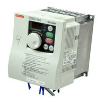
Mitsubishi FR - S500 Instruction Manual (196 pages)
TRANSISTORIZED INVERTER 3.7K-NA / 0.75K-NA
Brand:
Mitsubishi
| Category:
Inverter
| Size: 3.42 MB
Table of Contents
Table of Contents
6
Wiring
11
Standard Connection Diagram and Terminal Specifications
12
Standard Connection Diagram
12
Explanation of Main Circuit Terminals
13
Power Supply
14
Main Circuit Terminals
16
Terminal Block Layout
16
Cables, Wiring Length, and Crimping Terminals
18
Wiring Instructions
19
Selection of Peripheral Devices
20
Leakage Current and Installation of Ground Leakage Circuit Breaker
22
Power-Off and Magnetic Contactor (MC)
26
Regarding the Installation of the Power Factor Improving Reactor
27
Regarding Noise and the Installation of a Noise Filter
28
Grounding Precautions
29
Power Supply Harmonics
30
Inverter-Driven 400V Class Motor
31
How to Use the Control Circuit Terminals
32
Terminal Block Layout
32
Wiring Instructions
32
Changing the Control Logic
33
Input Terminals
35
Run (Start) and Stop (STF, STR, STOP)
35
Connection of Frequency Setting Potentiometer and Output Frequency Meter (10, 2, 5, 4, AU)
38
External Frequency Selection (REX, RH, RM, RL)
39
Indicator Connection and Adjustment (AM)
41
Control Circuit Common Terminals (SD, 5, SE)
42
Signal Inputs by Contactless Switches
42
How to Use the Input Signals (Assigned Terminals RL, RM, RH, STR)
43
Current Input Selection "AU Signal": Pr. 60 to Pr. 63 Setting "4
43
Multi-Speed Setting (RL, RM, RH, REX Signals)
43
Pr. 60 to Pr. 63 Setting "0, 1, 2
43
Remote Setting (RL, RM, RH Signals)
43
Second Function Selection (RT Signal): Pr. 60 to Pr. 63 Setting "3
43
Output Shut-Off (MRS Signal): Pr. 60 to Pr. 63 Setting "6
44
Start Self-Holding Selection (STOP Signal): Pr. 60 to Pr. 63 Setting "5
44
External Thermal Relay Input: Pr. 60 to Pr. 63 Setting "7
45
Jog Operation (JOG Signal): Pr. 60 to Pr. 63 Setting "9
45
Reset Signal: Pr. 60 to Pr. 63 Setting "10
46
PID Control Valid Terminal: Pr. 60 to Pr. 63 Setting "14
47
PU Operation/External Operation Switchover: Pr. 60 to Pr. 63 Setting "16
47
Connection to the Stand-Alone Option
48
Connection of the Brake Unit (BU Type)
48
Connection of the High Power Factor Converter (FR-HC)
49
Connection of the Power Regeneration Common Converter (FR-CV)
50
Handling of the RS-485 Connector
51
Connection of the Parameter Unit (FR-PU04)
51
Wiring of RS-485 Communication
52
Design Information
55
Functions
57
Function (Parameter) List
58
List of Parameters Classified by Purpose of Use
71
Explanation of Functions (Parameters)
73
Torque Boost (Pr. 0 , Pr. 46 )
73
Maximum and Minimum Frequency (Pr. 1 , Pr. 2 )
74
Base Frequency, Base Frequency Voltage (Pr.3 , Pr.19 , Pr.47 )
75
Acceleration/Deceleration Time (Pr. 7 , Pr. 8 , Pr. 20 , Pr. 44 , Pr. 45 )
77
Selection and Protection of a Motor (Pr. 9 , Pr. 71 , H7 )
79
DC Injection Brake (Pr. 10 , Pr. 11 , Pr. 12 )
81
Starting Frequency (Pr. 13 )
82
Load Pattern Selection (Pr. 14 )
83
Jog Operation (Pr.15 , Pr.16 )
84
RUN Key Rotation Direction Selection (Pr.17 )
84
Stall Prevention Function and Current Limit Function (Pr. 21 )
85
Stall Prevention (Pr. 22 , Pr. 23 , Pr. 28 )
87
Acceleration/Deceleration Pattern (Pr. 29 )
89
Extended Function Display Selection (Pr. 30 )
90
Frequency Jump (Pr. 31 to Pr. 36 )
90
Speed Display (Pr. 37 )
91
(Pr. 38 , Pr. 39 , C2 to C7 )
92
Biases and Gains of the Frequency Setting Voltage (Current)
92
Start-Time Ground Fault Detection Selection (Pr. 40 )
96
Output Terminal Function Parameters
96
Up-To-Frequency (Pr. 41 )
96
Output Frequency Detection (Pr. 42 , Pr. 43 )
97
Current Detection Function Parameters
98
Output Current Detection Functions (Pr. 48 , Pr. 49 )
98
Zero Current Detection (Pr. 50 , Pr. 51 )
99
Display Function Parameters
100
Monitor Display (Pr. 52 , Pr. 54 )
100
Setting Dial Function Selection (Pr. 53 )
101
Monitoring Reference (Pr. 55 , Pr. 56 )
102
Restart Operation Parameters
102
Restart Setting (Pr. 57 , Pr. 58 , H6 )
102
Parameter Setting
103
Additional Function Parameters
105
Remote Setting Function Selection (Pr. 59 )
105
Terminal Function Selection Parameters
108
Input Terminal Function Selection (Pr. 60 , Pr. 61 , Pr. 62 , Pr. 63 )
108
Output Terminal Function Selection (Pr. 64 , Pr. 65 )
110
Operation Selection Function Parameters
111
Retry Function (Pr. 66 , Pr. 67 , Pr. 68 , Pr. 69 )
111
PWM Carrier Frequency (Pr. 70 , Pr. 72 )
113
Voltage Input Selection (Pr. 73 )
114
Input Filter Time Constant (Pr. 74 )
115
Reset Selection/Pu Stop Selection (Pr. 75 )
115
Cooling Fan Operation Selection (Pr. 76 )
117
Parameter Write Disable Selection (Pr. 77 )
118
Operation Mode Selection (Pr. 79 )
119
Reverse Rotation Prevention Selection (Pr. 78 )
119
PID Control (Pr. 88 to Pr. 94 )
123
Auxiliary Parameters
130
Slip Compensation (Pr. 95 , Pr. 96 , Pr. 97 )
130
Automatic Torque Boost Selection (Pr. 98 )
131
Motor Primary Resistance (Pr. 99 )
132
Maintenance Parameters
132
Maintenance Output Function (H1, H2 )
132
Current Average Value Monitor Signal (H3, H4, H5)
133
Calibration Parameters
136
Meter (Frequency Meter) Calibration (C1 )
136
Clear Parameters
139
Alarm History Clear (ECL )
139
Parameter Clear (Clr )
139
Communication Parameters
140
Communication Settings (N1 to N7 , N11 )
142
Error Code List
155
Operation and Speed Command Source (N8 , N9 )
157
Link Startup Mode Selection (N10 )
158
E2PROM Write Selection (N12 )
160
Parameter Unit (FR-PU04) Setting
161
Caution
161
PU Buzzer Control (N14 )
161
PU Display Language Selection (N13 )
161
PU Contrast Adjustment (N15 )
162
PU Main Display Screen Data Selection (N16 )
162
Disconnected PU Detection/Pu Setting Lock Selection (N17 )
163
Protective Functions
165
Errors (Alarms)
166
Error (Alarm) Definitions
167
Correspondence between Digital and Actual Characters
175
Resetting the Inverter
175
To Know the Operating Status at the Occurrence of Alarm (Only When FR-PU04 Is Used)
175
Troubleshooting
176
Motor Remains Stopped
176
Acceleration/Deceleration Is Not Smooth
177
Motor Current Is Large
177
Motor Rotates in Opposite Direction
177
Speed Does Not Increase
177
Speed Greatly Differs from the Setting
177
Speed Varies During Operation
177
Motor Produces Annoying Sound
178
Operation Mode Is Not Changed Properly
178
Operation Panel Display Is Not Operating
178
Parameter Write Cannot be Performed
178
Specifications
179
Specification List
180
Ratings
180
Common Specifications
183
Outline Drawings
185
Appendix
189
APPENDIX 1 Parameter Instruction Code List
190
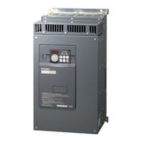
Mitsubishi FR - S500 Manual (167 pages)
Brand:
Mitsubishi
| Category:
Inverter Drive
| Size: 4.44 MB
Table of Contents
Table of Contents
1
System Configuration
2
System Configuration
3
External Devices Selection
9
Communication Settings
10
Setup Items
58
Cable Diagrams
62
Cable Diagram
74
Cable Diagram
84
Cable Diagram
97
Cable Diagram
98
Cable Diagram
119
Cable Diagram
120
Cable Diagram
130
Cable Diagram
137
Cable Diagram
144
Cable Diagram
145
Supported Devices
155
Device Code and Address Code
165
Error Messages
166
Advertisement
Advertisement
Related Products
Mitsubishi FR-F700
Mitsubishi FR-A701
Mitsubishi FR-V500
Mitsubishi FR-V500L
Mitsubishi FR-F500L
Mitsubishi FR-C500
Mitsubishi FRB-B
Mitsubishi FRB-B3A500
Mitsubishi FREQROL
Mitsubishi FR-E700 Series
Mitsubishi Categories
Air Conditioner
Controller
Projector
Automobile
Engine
More Mitsubishi Manuals
Login
Sign In
OR
Sign in with Facebook
Sign in with Google
Upload manual
Upload from disk
Upload from URL