Sign In
Upload
Manuals
Brands
Furuno Manuals
Marine Radar
FAR-2157-BB
Furuno FAR-2157-BB Manuals
Manuals and User Guides for Furuno FAR-2157-BB. We have
5
Furuno FAR-2157-BB manuals available for free PDF download: Operator's Manual, Installation Manual
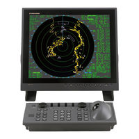
Furuno FAR-2157-BB Operator's Manual (305 pages)
Furuno Radar MARINE RADAR/ARPA Operator's Manual
Brand:
Furuno
| Category:
Marine Radar
| Size: 3.76 MB
Table of Contents
Table of Contents
7
Foreword
13
Program Number
16
System Configuration
17
Specifications
23
Display Unit
24
Power Supply
25
Optional Equipment
26
Radar Operation
27
Turning on the Power
27
Transmitter on
27
Control Unit
29
Main Menu
31
Operation Using the On-Screen Boxes
33
Cursor Menu
36
Monitor Brilliance
37
Choosing the Display Mode
38
On-Screen Boxes and Markers
39
Tuning the Receiver
41
Choosing the Tuning Method
41
Initializing Tuning
41
Automatic Tuning
42
Manual Tuning
42
Aligning Heading with Gyrocompass
42
Presentation Modes
43
Choosing Presentation Mode
43
Description of Presentation Modes
44
Entering Own Ship's Speed
47
Automatic Speed Input by Log or GPS Navigator
47
Manual Speed Input
48
Choosing the Range Scale
48
Choosing the Pulselength
49
Choosing Pulselength
49
Changing Pulselength
50
Adjusting the Sensitivity
51
Suppressing Sea Clutter
52
Choosing Method of Adjustment
52
Automatic Adjustment by the A/C SEA Control
52
Manual Adjustment of A/C SEA
53
Suppressing Rain Clutter
54
Turning AUTO RAIN on or off
54
Adjusting A/C RAIN
55
Interference Rejector
56
Measuring the Range
57
Turning Range Rings On/Off
57
Measuring Range by the Variable Range Marker (VRM)
58
Choosing VRM Unit of Measurement (B, C and W Types)
59
TTG to VRM Display
59
Measuring the Bearing
59
Choosing True or Relative Bearing
61
Collision Assessment by Offset EBL
62
How to Assess Risk of Collision by the Offset EBL
62
Choosing Point of Reference for Origin Point of Offset EBL
63
Measuring Range and Bearing between Two Targets
64
Setting a Target Alarm
65
How to Set a Target Alarm Zone
65
Acknowledging the Target Alarm
66
Deactivating a Target Alarm
66
Target Alarm Attributes
67
Off-Centering the Display
68
Echo Stretch
69
Echo Averaging
70
Target Trails
71
True or Relative Trails
71
Trail Time
72
Trail Gradation
72
Saving, Copying Target Trails
73
Trail Level
74
Narrow Trails (B, C and W Types)
74
Longer Trails (B, C and W Types)
75
Removing Trails from the Display Temporarily
75
Erasing Trails
75
Parallel Index Lines
76
Displaying, Erasing Parallel Index Lines
76
Adjusting Index Line Orientation, Index Line Interval
77
Index Line Bearing Reference
77
Choosing Maximum Number of Index Lines to Display
78
Index Line Mode
78
Origin Mark
79
Entering Origin Marks
79
Origin Mark Stabilization
81
Deleting Individual Origin Marks
81
Zoom
82
Markers
83
Heading Marker and Heading Line
83
Stern Marker
83
North Marker
83
Own Ship Symbol
83
Barge Marker
84
Automatic Picture Setup According to Navigation Purpose
85
Choosing a Picture Setup Option
87
Restoring Default Picture Setup Options
87
User-Programmable Picture Setups
88
Programming Function Keys
90
Activating a Function Key
90
Programming the Functions Keys
90
Ship's Position
95
Noise Rejector
96
Suppressing Second-Trace Echoes
97
Adjusting Brilliance of Screen Data
98
Watch Alarm
99
Setting up Nav Data
100
Text Window Setup
102
Customizing Operation
104
Alarms
106
Alarm Description
106
Outputting Alarm Signal
108
Choosing the Antenna, Displaying Antenna Information
109
1.44.1 Choosing the Antenna
109
Displaying Antenna Information
110
Cursor Data
111
Performance Monitor
112
Activating, Deactivating the Performance Monitor
112
Checking Radar Performance
112
Wiper
114
Own Ship Symbol
115
Color and Brilliance Sets
116
Choosing Color and Brilliance Set
116
Presetting Color and Brilliance Set
116
Reference Point for CPA/TCPA
117
Switching Hub HUB-100 (Option)
118
1.52 Dual Radar Display
119
Enabling/Disabling the Dual Radar Display
119
Specifying Sector Width and Length
122
Choosing External Radar (Image Source)
124
Radar Observation
125
General
125
Minimum and Maximum Ranges
125
False Echoes
127
SART (Search and Rescue Transponder)
129
SART Description
129
Showing SART Marks on the Radar Display
130
General Remarks on Receiving SART
131
Racon
132
Arp Operation
133
Usage Precautions
133
Controls for ARP
134
Activating, Deactivating ARP
135
Entering Own Ship's Speed
135
Echo-Referenced Speed Input
135
Automatic Acquisition
137
Enabling Auto Acquisition
137
Terminating Tracking of Targets (Including Reference Targets)
138
Manual Acquisition
139
Setting Manual Acquisition Conditions
139
Manually Acquiring a Target
139
ARP Symbols and ARP Symbol Attributes
141
ARP Symbols
141
Choosing ARP Symbol (B, C and W Types)
142
ARP Symbol Brilliance
142
ARP Symbol Color and Size
143
Auto Target Track (A, B, C and W Types)
144
Displaying Target Data
145
Displaying Individual Target Data
145
Target List
147
Vector Modes
149
Description of Vectors
149
Vector Motion and Length
150
Past Position Display
151
Displaying and Erasing Past Position Points, Choosing Past Position Plot Interval
151
Past Position Display Attributes
152
Set and Drift
153
Setting CPA/TCPA Alarm Ranges
154
Acknowledging CPA/TCPA Alarm
155
Setting a Guard Zone
156
Activating the Guard Zone
156
Sleeping, Deactivating a Guard Zone
157
Acknowledging the Guard Zone Alarm
157
Guard Zone Reference
158
Guard Zone Shape and Stabilization
158
Operational Warnings
159
Trial Maneuver
161
Types of Trial Maneuvers
161
Performing a Trial Maneuver
162
Terminating a Trial Maneuver
164
ARP Performance Test
165
Criteria for Selecting Targets for Tracking
167
Factors Affecting ARP Functions
169
Ais Operation
171
Controls for AIS
171
Enabling/Disabling the AIS
172
Turning AIS Display On/Off
173
Setting up for a Voyage
174
Activating Targets
176
Activating Specific Target
176
Activating All Targets
176
Sleeping Targets
177
Sleeping an AIS Target
177
Sleeping All AIS Targets
177
Displaying Target Data
178
Basic Data
178
Detailed Target Data
179
AIS Symbol Attributes
180
AIS Symbol Brilliance
180
AIS Symbol Size and Color
181
Past Position Display
182
Displaying and Erasing Past Position Points, Choosing Past Position Plot Interval
182
Past Position Display Attributes
183
Lost Target
184
ROT Setting
185
Fusion of ARP and AIS Targets
186
Own Ship's Data
188
Messages
189
Creating, Saving a Message
189
Transmitting a Message
190
Viewing AIS Messages
191
AIS System Messages
193
Video Plotter Operation
195
General
195
Display Modes
195
Presentation Modes
196
Radar Map
197
Turning on the Radar Map Display
197
Inscribing Radar Map Marks and Lines
198
Erasing Radar Map Marks and Lines
200
Erasing Individual Radar Map Marks and Lines
200
Erasing All Radar Map Marks and Lines
201
Radar Map Corrections
202
Radar Map Correction
202
Cursor Data Correction
202
Chart Cards (B, C and W Types)
203
Displaying a Chart
203
Chart Position Correction
204
Correcting Cursor Data
204
Chart Land Color
205
Hiding/Showing Graphics on the Video Plotter Display
206
Track
207
Plotting Own Ship's Track
207
Plotting Other Ships' Track (A, B, C and W Types)
208
Choosing Track Color
208
Erasing Track
209
Marks and Lines
210
Inscribing Marks and Lines
210
Erasing Marks and Lines
212
Erasing Individual Marks/Lines
212
Erasing All Marks and Lines
213
Waypoints
214
Entering Waypoints
214
Editing, Erasing Waypoints from the Menu
217
Erasing Waypoints
218
Waypoint List
219
Displaying Waypoint Name and Number
220
Nav Lines
221
Entering New Nav Line
221
Editing Nav Lines
222
Nav Line List
223
Erasing Nav Lines
224
Setting up Nav Lines
225
Displaying Nav Line, Waypoint Mark
227
Recording Data
229
Initializing Memory (RAM) Cards
229
Recording Data
230
Replaying Data
232
Deleting Files
233
Maintenance, Troubleshooting
235
Periodic Maintenance Schedule
236
Life Expectancy of Major Parts
237
Replacing the Fuse
237
Replacement of Battery on GC Board
238
Trackball Maintenance
238
Easy Troubleshooting
239
Advanced-Level Troubleshooting
240
Diagnostics
243
Self Test
244
System Messages
246
Appendix
249
Menu Tree
249
Digital Interface
256
Parts Lists and Parts Location
277
Parts Location
283
Longitude Error Table (on 96 Nm Range Scale
293
Index
295
Declaration of Conformity
299
Advertisement
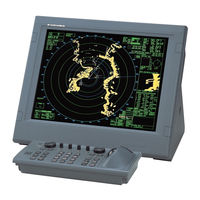
Furuno FAR-2157-BB Operator's Manual (299 pages)
MARINE RADAR/ARPA
Brand:
Furuno
| Category:
Marine Radar
| Size: 3.63 MB
Table of Contents
Table of Contents
7
Foreword
13
Program Number
16
System Configuration
17
Specifications
23
Display Unit
24
Power Supply
25
Optional Equipment
26
Radar Operation
27
Turning on the Power
27
Transmitter on
27
Control Unit
29
Main Menu
31
Operation Using the On-Screen Boxes
33
Cursor Menu
36
Monitor Brilliance
37
Choosing the Display Mode
38
On-Screen Boxes and Markers
39
Tuning the Receiver
41
Choosing the Tuning Method
41
Initializing Tuning
41
Automatic Tuning
42
Manual Tuning
42
Aligning Heading with Gyrocompass
42
Presentation Modes
43
Choosing Presentation Mode
43
Description of Presentation Modes
44
Entering Own Ship's Speed
47
Automatic Speed Input by Log or GPS Navigator
47
Manual Speed Input
48
Choosing the Range Scale
48
Choosing the Pulselength
49
Choosing Pulselength
49
Changing Pulselength
50
Adjusting the Sensitivity
51
Suppressing Sea Clutter
52
Choosing Method of Adjustment
52
Automatic Adjustment by the A/C SEA Control
52
Manual Adjustment of A/C SEA
53
Suppressing Rain Clutter
54
Turning AUTO RAIN on or off
54
Adjusting A/C RAIN
55
Interference Rejector
56
Measuring the Range
57
Turning Range Rings On/Off
57
Measuring Range by the Variable Range Marker (VRM)
58
Choosing VRM Unit of Measurement (B, C and W Types)
59
Measuring the Bearing
59
Choosing True or Relative Bearing
61
Collision Assessment by Offset EBL
62
How to Assess Risk of Collision by the Offset EBL
62
Choosing Point of Reference for Origin Point of Offset EBL
63
Measuring Range and Bearing between Two Targets
64
Setting a Target Alarm
65
How to Set a Target Alarm Zone
65
Acknowledging the Target Alarm
66
Deactivating a Target Alarm
66
Target Alarm Attributes
67
Off-Centering the Display
68
Echo Stretch
69
Echo Averaging
70
Target Trails
71
True or Relative Trails
71
Trail Time
72
Trail Gradation
72
Saving, Copying Target Trails
73
Trail Level
74
Narrow Trails (B, C and W Types)
74
Longer Trails (B, C and W Types)
75
Removing Trails from the Display Temporarily
75
Erasing Trails
75
Parallel Index Lines
76
Displaying, Erasing Parallel Index Lines
76
Adjusting Index Line Orientation, Index Line Interval
77
Index Line Bearing Reference
77
Choosing Maximum Number of Index Lines to Display
78
Index Line Mode (B, C and W Types)
78
Origin Mark
79
Entering Origin Marks
79
Origin Mark Stabilization
81
Deleting Individual Origin Marks
81
Zoom
82
Markers
83
Heading Marker and Heading Line
83
Stern Marker
83
North Marker
83
Own Ship Symbol
83
Barge Marker
84
Automatic Picture Setup According to Navigation Purpose
85
Choosing a Picture Setup Option
87
Restoring Default Picture Setup Options
87
User-Programmable Picture Setups
88
Programming Function Keys
90
Activating a Function Key
90
Programming the Functions Keys
90
Ship's Position
95
Noise Rejector
96
Suppressing Second-Trace Echoes
97
Adjusting Brilliance of Screen Data
98
Watch Alarm
99
Setting up Nav Data
100
Text Window Setup
102
Customizing Operation
104
Alarms
106
Alarm Description
106
Outputting Alarm Signal
108
Choosing the Antenna, Displaying Antenna Information
109
1.44.1 Choosing the Antenna
109
Displaying Antenna Information
110
Cursor Data
111
Performance Monitor
112
Activating, Deactivating the Performance Monitor
112
Checking Radar Performance
112
Wiper
114
Own Ship Symbol
115
Color and Brilliance Sets
116
Choosing Color and Brilliance Set
116
Presetting Color and Brilliance Set
116
Reference Point for CPA/TCPA
117
Switching Hub HUB-100 (Option)
118
Radar Observation
119
General
119
Minimum and Maximum Ranges
119
False Echoes
121
SART (Search and Rescue Transponder)
123
SART Description
123
Showing SART Marks on the Radar Display
124
General Remarks on Receiving SART
125
Racon
126
Arp Operation
127
Usage Precautions
127
Controls for ARP
128
Activating, Deactivating ARP
129
Entering Own Ship's Speed
129
Echo-Referenced Speed Input
129
Automatic Acquisition
131
Enabling Auto Acquisition
131
Terminating Tracking of Targets (Including Reference Targets)
132
Manual Acquisition
133
Setting Manual Acquisition Conditions
133
Manually Acquiring a Target
133
ARP Symbols and ARP Symbol Attributes
135
ARP Symbols
135
Choosing ARP Symbol (B, C and W Types)
136
ARP Symbol Brilliance
136
ARP Symbol Color and Size
137
Auto Target Track (A, B, C and W Types)
138
Displaying Target Data
139
Displaying Individual Target Data
139
Target List
141
Vector Modes
143
Description of Vectors
143
Vector Motion and Length
144
Past Position Display
145
Displaying and Erasing Past Position Points, Choosing Past Position Plot Interval
145
Past Position Display Attributes
146
Set and Drift
147
Setting CPA/TCPA Alarm Ranges
148
Acknowledging CPA/TCPA Alarm
149
Setting a Guard Zone
150
Activating the Guard Zone
150
Sleeping, Deactivating a Guard Zone
151
Acknowledging the Guard Zone Alarm
151
Guard Zone Reference
152
Guard Zone Shape and Stabilization
152
Operational Warnings
153
Trial Maneuver
155
Types of Trial Maneuvers
155
Performing a Trial Maneuver
156
Terminating a Trial Maneuver
158
ARP Performance Test
159
Criteria for Selecting Targets for Tracking
161
Factors Affecting ARP Functions
163
Ais Operation
165
Controls for AIS
165
Enabling/Disabling the AIS
166
Turning AIS Display On/Off
167
Setting up for a Voyage
168
Sleeping an AIS Target
171
Sleeping All AIS Targets
171
Basic Data
172
Displaying Target Data
172
Detailed Target Data
173
AIS Symbol Attributes
174
AIS Symbol Brilliance
174
AIS Symbol Size and Color
175
Past Position Display
176
Displaying and Erasing Past Position Points, Choosing Past Position Plot Interval
176
Past Position Display Attributes
177
Lost Target
178
ROT Setting
179
Fusion of ARP and AIS Targets
180
Own Ship's Data
182
Messages
183
Creating, Saving a Message
183
Transmitting a Message
184
Viewing AIS Messages
185
AIS System Messages
187
Video Plotter Operation
189
General
189
Display Modes
189
Presentation Modes
190
Radar Map
191
Turning on the Radar Map Display
191
Inscribing Radar Map Marks and Lines
192
Erasing Radar Map Marks and Lines
194
Erasing Individual Radar Map Marks and Lines
194
Erasing All Radar Map Marks and Lines
195
Radar Map Corrections
196
Radar Map Correction
196
Cursor Data Correction
196
Chart Cards (B, C and W Types)
197
Displaying a Chart
197
Chart Position Correction
198
Correcting Cursor Data
198
Chart Land Color
199
Hiding/Showing Graphics on the Video Plotter Display
200
Track
201
Plotting Own Ship's Track
201
Plotting Other Ships' Track (A, B, C and W Types)
202
Choosing Track Color
202
Erasing Track
203
Marks and Lines
204
Inscribing Marks and Lines
204
Erasing Marks and Lines
206
Erasing Individual Marks/Lines
206
Erasing All Marks and Lines
207
Waypoints
208
Entering Waypoints
208
Editing, Erasing Waypoints from the Menu
211
Erasing Waypoints
212
Waypoint List
213
Displaying Waypoint Name and Number
214
Nav Lines
215
Entering New Nav Line
215
Editing Nav Lines
216
Nav Line List
217
Erasing Nav Lines
218
Setting up Nav Lines
219
Displaying Nav Line, Waypoint Mark
221
Recording Data
223
Initializing Memory (RAM) Cards
223
Recording Data
224
Replaying Data
226
Deleting Files
227
Maintenance, Troubleshooting
229
Periodic Maintenance Schedule
230
Life Expectancy of Major Parts
231
Replacing the Fuse
231
Replacement of Battery on GC Board
232
Trackball Maintenance
232
Easy Troubleshooting
233
Advanced-Level Troubleshooting
234
Diagnostics
237
Self Test
238
System Messages
240
Appendix
243
Menu Tree
243
Digital Interface
250
Parts Lists and Parts Location
271
Parts Location
277
Longitude Error Table (on 96 Nm Range Scale
287
Index
289
Furuno FAR-2157-BB Installation Manual (112 pages)
Furuno Marine RADAR User Manual
Brand:
Furuno
| Category:
Marine Radar
| Size: 4.76 MB
Table of Contents
Table of Contents
1
Radio Frequency Radiation Hazard
3
Safety Instructions
3
System Configuration
5
Equipment Lists
6
Optional Equipment
6
Standard Supply
6
Antenna Unit
9
Mounting Considerations
9
Assembling the Antenna Unit
10
How to Coat Waveguide Flange with Silicon Rubber
10
List of Parts for Assembling Antenna Unit
11
Parts of Antenna Unit XN4A/XN5A
11
How to Hoist Antenna Unit
12
Fastening Antenna Unit to the Mounting Platform
13
Flush Mounting
15
Monitor Unit
15
Mounting Dimensions for Flush Mounting the Monitor Unit
15
Mounting Procedure
15
Contents of Desktop Mounting Kit FP03-09820
16
Desktop Mounting
16
Attaching Hand Grips
17
Attaching Hood
17
Contents of Hood
17
Fastening Monitor Unit to Hanger
17
Control Unit
18
Control Unit RCU-014/015/016, Side View
18
Fixing with KB (Keyboard) Fixing Plate
18
Fixing Without KB Fixing Plate
19
Mounting Dimensions for Control Unit RCU-014
19
Mounting Dimensions for Control Unit RCU-015/RCU-016
19
Contents of Flush Mount Kit for RCU-014/015/016
20
Connecting RCU-016 in Series with RCU-014
21
Changing Cable Entrance on Control Unit RCU-015/RCU-016
22
Changing the Cable Entrance on Control Unit RCU-015/RCU-016
22
Mounting Dimensions for Processor Unit
23
Processor Unit
23
Mounting Dimensions for Power Supply Unit
24
Power Supply Unit
24
Wiring Overview
25
Antenna Unit, Front View
26
Fabricating Signal Cable RW-9600
26
How to Wire WAGO Connector
28
How to Fasten Coaxial Conductor
29
Fabricating HV Cable TYPCY-1.5 and Power Cable TYPCY-2.5
30
How to Fabricate HV Cable TYPCY-1.5
30
Passing Flat Washer, Etc. Onto HV Cable
30
How to Fabricate Power Cable TYPCY-2.5
31
Passing Flat Washer, Etc. Onto Power Cable
31
Fabricating Power Cable DPYC-2.5
32
Fabricating the Power Cable DPYC-2.5
32
Monitor Unit (for FAR-2157)
32
Monitor Unit MU-201CR, Rear View
32
Processor Unit
33
Cable XH10P-W-5P-A L=10/20/30M
34
Cable XH10P-W-6P L=20/30M
34
Connection of Cables
34
Processor Unit, Rear View
34
Location of Connectors
35
Location of Connectors Inside the Processor Unit
35
Cable Fabrication for the Cables Connected to the 03P9342 Board
36
Cables for Optional Equipment (Use TTYCS-1 or TTYCS-4, or Equivalent)
36
Power Cable TPYC-1.5
36
Signal Cable RW-9600 (between Antenna Unit and Processor Unit)
36
Connection of Sub-Display
37
Fabricating Cable Connected to Terminal TB1, TB2, TB3
38
Power Supply Unit, Inside View
38
Terminal TB1: Cable DPYC-2.5
38
Terminal TB2: Cable TPYC-2.5 (for Antenna Motor)
39
Changing AC Power Specification
40
Processor Unit, Inside View
40
How to Adjust the Overvoltage Detection Circuit:
41
How to Adjust the Overvoltage Detection Circuit
42
Adjustments
43
ECHO Menu
43
Initializing Tuning
43
Heading Alignment
44
For Control Unit RCU-014
45
How to Access the INITIALIZE Menu with Control Unit RCU-015
46
How to Adjust Heading of External Radar from this Radar
46
Adjusting Sweep Timing
47
ECHO ADJ Menu
47
Examples of Correct and Incorrect Sweep Timings
47
Suppressing Main Bang
48
Cable Att Adj
49
Default Ant Height
49
ECHO Menu Setting
49
Other Settings
49
Ant Revolution
50
ANT SW and ANT STOPPED
50
BLIND SECTOR 1 and BLIND SECTOR 2
50
SCANNER Menu
50
INSTALLATION Menu
51
Radar
51
RADAR no and RADAR POSN
51
Range Unit
51
Conning Posn
52
GPS 1 ANT POSN and GPS 2 ANT POSN
52
LENGTH/WIDTH, SCANNER POSN and SUB SCANNER POSN
52
OWN SHIP INFO Menu
52
ARPA PRESET Menu
53
Echo Level
53
Max Range
53
Ttm Output
53
Ant Select
54
Auto Acq Corre
54
Auto Acq Weed
54
Land Size
54
Arp Select
55
EAV W/O GYRO
55
Ins
55
OTHER Menu
55
Gyro Converter GC-10
57
Installing the GYRO CONVERTER Board
57
4 Optional Equipment
57
Fixing GYRO CONVERTER Board Inside the Processor Unit
58
Connecting Connector Assemblies Inside Processor Unit
59
Connection for J602
59
Connection for P608
59
Wiring WAGO Connector
59
Attaching Plastic Cover for GYRO CONVERTER Board
60
Connection of External Power Supply
61
Connection of External Power Supply to GYRO CONVERTER Board
61
DIP Switch, Jumper Wire Settings
61
Frequency
62
Gyrocompass Type
62
Rotor Voltage (between R1 & R2)
62
Setting Method 1: DIP Switch Settings and Gyrocompass Specifications
62
Setting Method 2: by Make and Model of Gyrocompass
63
Location of DIP Switches, Jumper Wires on the GYRO CONVERTER Board
64
HDG Menu
65
Setting the Heading Readout on the Radar Display
65
Flush Mounting Dimensions for Memory Card Interface Unit
66
Memory Card Interface Unit
66
Desktop Mount
67
One Memory Card if Unit and Multiple Processor Units
67
One Memory Card if Unit and One Processor Unit
67
Armored LAN Cable Kit
68
Memory Card Interface Unit, Showing Location of DIP Switch S1
68
DVI-RGB Conversion Kit
69
How to Wire the DVI-RBG Conversion Board
69
Processor Unit (Bottom Chassis)
70
Processor Unit, Side View
70
Connecting Wires to the Housing
71
Fixing the DVI-RGB Conversion Board Inside the Processor Unit
71
BNC Connector Converter
72
Connecting VR-5000 to FAR-2157(-BB) Via BNC Connector Converter
72
5 Io Data
73
Input
73
Output
73
IEC 61162 Input Sentence and Priority
74
IEC 61162 Output Sentence
74
Packing List
75
Interconnection Diagram
111
Advertisement
Furuno FAR-2157-BB Installation Manual (111 pages)
Furuno Marine RADAR User Manual
Brand:
Furuno
| Category:
Marine Radar
| Size: 4.76 MB
Table of Contents
Table of Contents
1
Safety Instructions
3
System Configuration
5
Equipment Lists
6
1 Mounting
9
Antenna Unit
9
Mounting Considerations
9
Monitor Unit
15
Control Unit
18
Processor Unit
23
Power Supply Unit
24
2 Wiring
25
Wiring Overview
25
Antenna Unit
26
Monitor Unit (for FAR-2157)
32
Processor Unit
33
Power Supply Unit
38
Changing AC Power Specification
40
3 Adjustment
43
Initializing Tuning
43
Heading Alignment
44
Adjusting Sweep Timing
47
Suppressing Main Bang
48
Other Settings
49
4 Optional Equipment
57
Gyro Converter GC-10
57
Memory Card Interface Unit
66
DVI-RGB Conversion Kit
69
BNC Connector Converter
72
5 Io Data
73
Packing Lists
88
Interconnection Diagram
111
Furuno FAR-2157-BB Operator's Manual (20 pages)
Brand:
Furuno
| Category:
Marine Radar
| Size: 0.48 MB
Advertisement
Related Products
Furuno FAR-2157
Furuno FAR-2157-D
Furuno FAR-2117
Furuno FAR-2127
Furuno FAR-2137S
Furuno FAR-2117-BB
Furuno FAR-2127-BB
Furuno FAR-2167DS-BB
Furuno FAR-2167DS-D
Furuno FAR-21x7(-BB) Series
Furuno Categories
Marine Radar
Marine Equipment
Sonar
Monitor
GPS
More Furuno Manuals
Login
Sign In
OR
Sign in with Facebook
Sign in with Google
Upload manual
Upload from disk
Upload from URL