Sign In
Upload
Manuals
Brands
Alcatel Manuals
Network Hardware
MTK-40131
Alcatel MTK-40131 Manuals
Manuals and User Guides for Alcatel MTK-40131. We have
1
Alcatel MTK-40131 manual available for free PDF download: Datasheet And User Manual
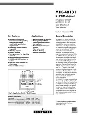
Alcatel MTK-40131 Datasheet And User Manual (56 pages)
SH POTS chipset
Brand:
Alcatel
| Category:
Network Hardware
| Size: 0.46 MB
Table of Contents
Key Features
1
Applications
1
General Description
1
Fig. 1: Application Sketch / Block Diagram
1
Fig. 2: Device Pinouts
2
Table of Contents
3
Pin Description
7
Table 1: Pin Description for MTC-20232PQ CODSP
7
Table 2: Pin Description for MTC-30132SO SH LIC
8
Application Schematic
9
Fig. 3: Application Schematic for 2 Analog Lines (See Table 3 for Component Values)
9
Table 3: Recommended External Components
10
Unused Pins
11
Table 4: MTC-20232 CODSP Unused Pin Connections
11
Table 5: MTC-30132 SH LIC Unused Pin Connections
11
Note on Decoupling
12
Fig. 4: MTC-20132 CODSP Recommended Power-Supply Decoupling Arrangements
12
Overvoltage Protection
13
Fig. 5: Recommended Overvoltage Protection Options
13
Functional Characteristics of the SH POTS System
14
Fig. 6: SH POTS Line Voltages - Example
14
On-Hook Conditions
15
Fig. 7: Nominal Hook-Switch Detection Thresholds (Default Values)
15
Table 6: Table 6: On-Hook Characteristics
15
Ringing Injection
16
Table 7: Ringing Characteristics
16
DC Feed Characteristics
17
Battery Voltage and Reversal
17
Fig. 8: DC Feed Characteristics
17
Table 8: DC Feed Characteristics (Rfeed = 60Ω Total (50Ω+10Ω Protection) X2)
17
AC Transmission Characteristics (MTK-40131 System)
18
Transmit and Receive Gain
18
Fig. 9: Transmit and Receive Frequency Response (Default)
18
Fig. 10: Relative Group Delay, Transmit and Receive Paths (Digital to Digital) Refered to 1Khz
18
Source Impedance (Zco)
19
Balance Impedance (Echo Canceller)
19
Fig. 11: 3-Element Zco Model
19
Table 9: Examples of ZCO Coëfficients
19
Off-Hook Characteristics (MTK-40131 System)
20
Table 10: Off-Hook Characteristics (MTK-40131 System)
20
Metering Injection
21
Fig. 12: Metering Pulse Timing Diagrams
21
Table 11: Metering Characteristics (Determinized by MTC-20232 CODSP)
22
Tone Generation
23
Table 12: Tone Signal Levels (Common Values)
23
Table 13: Tone Generator Characteristics
24
Table 14: Tone Generator Division Values for Common Frequencies from ETS-300-001, and DTMF Tones
24
Table 15: Required Frequency Setting Values (N) for a Melody Generator (Western Equal-Tempered Scale)
25
CODSP Clock Recovery PLL
26
User-Defined I/O Pins
26
Fig. 13: Application Suggestion for Semi-Unbalanced Ringing Injection
26
Electrical Characteristics
27
Absolute Maximum Ratings
27
Operating Conditions
27
Table 16: Absolute Maximum Ratings
27
Table 17: Operating Conditions
27
Thermal Shutdown SHLIC
28
Transient Energy Capability
28
Table 18: SHLIC Dissipation
28
DC Characteristics (MTC-30132 SHLIC, Unless Otherwise Noted)
29
Power Supply Currents
29
Table 19: Power Supply Currents
29
Power-On Reset
30
V3V Regulator
30
Table 20: Power-On Reset Characteristics
30
Table 21: V3V Regulator Characteristics
30
AW, BW DC- Levels, Impedances
31
Table 22: Voltage Characteristics a Wire, B Wire
31
Table 23: Impedance Characteristics a Wire, B Wire
31
RX, TX DC- Levels, Impedances
32
DCO DC- Levels, Impedances
32
VAG Analog Ground Input
32
Table 24: RX, TX Characteristics
32
Table 25: DCO Characteristics
32
Table 26: VAG Characteristics
32
SA,SB Sense Bridge Inputs
33
DC Loop Filter
33
DCC Input Pin
33
Table 27: Sense Bridge Inputs Characteristics
33
Table 28: DC Loop Filter Characteristics
33
Table 29: DCC Input Characteristics
33
Characteristics for the Digital I/O Pins
34
Test Switch
34
Table 30: Digital I/O Characteristics
34
Battery Switch
35
Table 31: Test Switch Characteristics
35
Table 32: Ringing Battery Switch Characteristics
35
AC Characteristics (SHLIC)
36
Fig. 14: Block Diagram Showing the Gains in the Various Signal Paths in the SHLIC
36
Table 33: Typical Gains
36
Overpower and Short Circuit Protection
37
Fig. 15: Short Circuit Protection
37
Quality / Reliability
38
Table 34: Short Circuit Protection Characteristics
38
Detailed Programming Description
39
GCI Interface
39
Fig. 16: GCI Data Exchange
39
Fig. 17: GCI Timing Diagram
40
Table 35: GCI Mode and Timeslot Address Programming
40
Table 36: GCI Interface: Timing Characteristics
41
C/I Bits
42
C/I Bit Allocation:C/I Bit Allocation
42
Monitor Channel
42
ID Response
42
Read Command
43
Write Command
43
Memory Map of the CODSP
43
Global Memory Map and Memid Definitions
43
Data RAM
44
Table 37: Memory Map for CODSP
44
Table 38: Data RAM: Memory Map
44
Table 39: LBO Register Description
46
Meaning and Default Values of the Parameters
47
Table 40: Data RAM: Description and Default Values
47
Coprocessor Coefficient RAM
50
Table 41: Coprocessor Coefficient RAM: Memory Map
50
Meaning and Default Values of the Parameters
52
Table 42: Coprocessor Coefficient RAM: Description and Default Values
52
SHARED Memory
53
Table 43: Shared Memory: Memory Map
53
Meaning and Default Values of the Parameters
54
Table 44: Shared Memory: Description and Default Values
54
Packages
55
General Dimensions of the MTC-20232PQ
55
General Dimensions of the MTC-30132SO
56
Advertisement
Advertisement
Related Products
Alcatel MTC-20172
Alcatel OmniPCX Office IPTouch MIPT 300
Alcatel Move
Alcatel Modem
ALCATEL MANDARINA DUCK MOON
Alcatel MDR-8000
Alcatel Mobile Phone
Alcatel MOVETIME
Alcatel MOVEBAND MB10N
Alcatel MOVETIME Track & Talk watch
Alcatel Categories
Cell Phone
Telephone
Tablet
IP Phone
Switch
More Alcatel Manuals
Login
Sign In
OR
Sign in with Facebook
Sign in with Google
Upload manual
Upload from disk
Upload from URL