Sign In
Upload
Manuals
Brands
ABB Manuals
Other
SACE Emax E1.2
ABB SACE Emax E1.2 Manuals
Manuals and User Guides for ABB SACE Emax E1.2. We have
4
ABB SACE Emax E1.2 manuals available for free PDF download: Operating Instructions For The Design Engineer, Operating Instructions Manual, Instructions For Use Manual, Manual
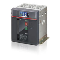
ABB SACE Emax E1.2 Operating Instructions For The Design Engineer (311 pages)
SACE Emax 2 series Low voltage air circuit-breakers
Brand:
ABB
| Category:
Other
| Size: 32.87 MB
Table of Contents
Table of Contents
3
II | © 2017 ABB SACE Emax
8
Circuit-Breakers E1.2-E2.2-E4.2-E6.2
10
Foreword
10
Contents
10
Standards
10
Guide to the Product Choice
11
List for Emax 2 Selection
11
Foreword
11
Device
11
Standard
11
Mechanical Characteristics
11
Electrical Characteristics
12
Protection Functions of the Electronic Trip Units
13
Electrical and Mechanical Accessories
14
Electronic Accessories
14
Selectivity between ABB SACE Circuit-Breakers
15
Foreword
15
Types of Selectivity
15
Further Documents
15
Documents and Tools for the Design Engineer
16
Foreword
16
Software List
16
E-Design
16
Doc
16
Cat
16
Curves
16
Docsolar
16
Otc
16
Front CAD
17
Trip Unit Simulator
17
Ekip Connect
17
Slide Rules
17
Ekip View
17
Documentation List
18
Brochure: Introductory Overview
18
Brochure: History of Air Circuit-Breakers
18
Brochure: Retrofitting Kit
18
Product Notes for Consultants
18
Product Notes for Switchgear Engineers
18
Product Notes the Ekip Link System
18
Product Notes for Power Controller
18
Product Notes for Generator Protections
18
Product Notes: Migration to Emax 2
18
White Paper for Generator Protections
19
White Paper for Ekip Power Controller
19
White Paper for Communication
19
Product Notes for IEC 61850
19
Product Notes for Network Analyzer
19
Catalogue
19
Handbook
19
Introduction to Ekip Trip Units
20
Presentation
20
Families and Functionality
20
Protections
21
Measurements
22
Integrated Functions: Self-Diagnosis, Test and Power Controller
22
Accessorizing Modules
23
Ekip Dip Protection Trip Unit
24
Operator Interface
24
Introduction
24
Components of the Interface
24
Leds
24
Protections: Thresholds
25
Protections: Times
25
Settings
25
Itest Pushbutton
25
Test Connector
25
Protections
26
L Protection
26
S Protection
27
I Protection
28
G Protection
29
Neutral and Frequency
30
Additional Protections
31
Summary Table of Protections
32
Measurements
33
Introduction Measurements
33
Instantaneous Currents
33
Maximum and Minimum Currents
33
Trips
33
Contact Wear
33
Number of Operations
33
Test
34
Presentation
34
LED Test
34
Battery Test
34
Protection Test
34
Opening Test
34
List of Alarms and Signals
35
LED View
35
Summary Table of LED Signals
36
Ekip Dip: Additional Functions
38
Presentation
38
Maintenance
38
Local Bus
38
Date and Time
38
Programmable States
39
Programmable Functions
39
Circuit-Breaker Label and User Data
40
Info Page
40
Date of Installation
40
Load Profile Timers
40
Energy Store Time
40
Led Alive
40
Open/Close Remote Direct Command
40
Modules Network Settings Retention
40
Wink
40
Glitch
40
Operating Features
41
Primary Operating Currents
41
Auxiliary Power Supply
41
Default Parameters
42
Ekip Touch Protection Trip Unit
43
Layout of the Interface
43
Functions of the Interface
43
Components of the Interface
43
Signallings
44
Structure of the
44
Diagnosis Bar
45
Main Page
45
Start Page
46
Navigation
46
Alarm List Page
47
Description
47
Components of the Page
47
Histograms Page
48
Description
48
Components of the Page
48
Possible Operations
49
Measuring Instruments
50
Description
50
Components of the
50
Possible Operations
50
Measurements
51
Description
51
Components of the
51
Possible Operations
51
Menu
52
Introduction
52
Components of the Page
52
Components of the Menus
53
Protections Menu
53
Advanced Menus
54
Settings Menu
55
Test Menu
56
About Menu
57
Measurements Menu
57
Last Trip Measurements
58
Measurements History
59
Waveforms
60
Harmonics Measurement
61
Insertion of the Password
62
Function
62
Description
62
Components of the Page
63
Setting the Parameters
64
Modifying a Parameter
64
Programming the Trip Unit
64
Edit Parameters Page by Option
65
Edit Parameters Page by Value
65
Programming Page
66
Touch Protections
67
Presentation
67
L Protection
68
S Protection
69
I Protection
70
G Protection
71
Protection
72
Protection MCR
73
IU Protection
74
Hardware Trip
74
Harmonic Distortion
74
Current Thresholds
75
T Protection
76
Neutral
76
Iinst
77
Additional Functions
77
Summary Table of Basic Protections
79
Measuring Pro Protections
81
Presentation
81
UV Protection
82
OV Protection
82
VU Protection
83
UF Protection
83
OF Protection
84
RP Protection
84
Phase Sequence
85
Cos Φ
85
Synchrocheck
85
Summary Table of Measuring Pro Protections
86
Hi-Touch Protections
87
Presentation
87
S2 Protection
88
D Protection
89
UV2 Protection
90
OV2 Protection
91
UF2 Protection
91
OF2 Protection
92
Set A-B
93
Hi- Versions: Additional Functions
94
Summary Table of Hi-Touch Protections
95
Table of Additional Functions of the Protections
95
G Touch Protections
96
Presentation
96
S(V) Protection
97
RV Protection
98
RQ Protection
98
OQ Protection
99
OP Protection
100
UP Protection
100
Summary Table for G Touch Protections
101
Table of Additional Functions of the Protections
101
G Hi-Touch Protections
102
Presentation
102
ROCOF Protection
103
S(V) Protection
104
RQ2 Protection
105
Summary Table of G Hi-Touch Protections
106
External Toroid Protections
107
Presentation
107
Gext Protection
107
RC Protection
109
Summary Table of External Toroid Protections
110
Table of Additional Function of the Gext Protection
110
Touch Measurements
111
Presentation
111
Instantaneous Currents
111
Tripping
111
Events
112
Maximum and Minimum Currents
113
Peak Factor
113
Contact Wear
114
Datalogger
114
Operation Counters
115
Summary Table of Basic Measurements
115
Ekip Measuring Measurements
116
Presentation
116
Instantaneous Voltages
116
Instantaneous Power
117
Tripping
117
Maximum and Minimum Voltage
118
Maximum and Minimum Power
118
Power Factor
119
Energy Counters
119
Instantaneous Frequency
119
Synchrocheck
119
Summary Table of Ekip Measuring Measurements
119
Hi-Touch Measurements
120
Presentation
120
Waveforms
120
Harmonics
120
Network Analyzer
120
Test
124
Path
124
Presentation
124
Autotest
124
Trip Test
124
Test CB
124
Zone Selectivity
125
Ekip Signalling
125
Rc Test
125
Self-Diagnosis
126
Alarms and Signals
126
Protections and Measurements
127
Programming Errors
128
Operating Features
129
Electrical Characteristics
129
Additional Ekip Touch Functions
130
Functional Characteristics
130
Line Frequency
130
Local/Remote
130
Local Bus
130
Harmonics
130
Power Controller
130
Programmable Functions
131
System
131
Maintenance
131
Additional Options Via Remote / Front Control
132
Programmable States
132
Filters
132
Circuit-Breaker Label and User Data
132
Info Page
132
Date of Installation
133
Load Profile Timers
133
Energy Store Time
133
Led Alive
133
Open/Close Remote Direct Command
133
Modules Network Settings Retention
133
Change Double Set of Parameters Always
133
Repeat Zone Selectivity S/G HW
133
Zone Selectivity Input Functions
133
Wink
134
Glitch
134
Wizard Reset
134
Default Parameters
135
Ekip Touch Default Parameters
135
Ekip Power Controller
137
Presentation
137
Trip Units
137
Parameters on the Display
137
Measurements on the Display
137
Information Displayed
137
Protection Curves
138
Introduction
138
DIP Protections
139
Tripping Curve for L-I Protections
139
Tripping Curve for L-S(T = K / I )-I Protections
140
Tripping Curve for L-S(T = K)-I Protections
141
Tripping Curves for G Protection (T = K / I 2 )
142
Tripping Curves for G Protection (T = K)
143
Touch Protections
144
Tripping Curve for L-I Protections
144
Tripping Curve for L-S(T = K / I )-I Protections
145
Tripping Curve for L-S(T = K)-I Protections
146
Tripping Curves for Protection L According to IEC 60255
147
Tripping Curves for G Protection (T = K / I 2 )
147
Tripping Curves for G Protection (T = K)
150
Tripping Curves for IU Protection
151
Measuring Pro Protections
152
Tripping Curves for UV Protection
152
Tripping Curves for Protection OV
152
Tripping Curves for VU Protection
153
Tripping Curves for Protection UF
153
Tripping Curves for Protection of
154
Tripping Curves for RP Protection
154
Hi-Touch Protections
155
Tripping Curves for Protection D
155
G Touch Protections
156
Tripping Curves for S(V) Protection
156
Tripping Curves for Protection RV
156
Tripping Curves for RQ Protection
157
Tripping Curves for OQ Protection
157
Tripping Curves for OP Protection
158
Tripping Curves for up Protection
158
G Hi-Touch Protections
159
Tripping Curves for Protection ROCOF
159
External Toroid Protections
160
Tripping Curves for Protection Rc
160
System Interface
161
Documents
161
Specific Applications
162
Zone Selectivity
162
Description
162
Zone Selectivity with ABB SACE Circuit-Breakers
162
Zone Selectivity with SACE Emax 2 Circuit-Breakers
163
Load Control
165
General Description
165
Operating Details
165
Connections and Equipment
166
Access from the Ekip Connect
168
Access from the Display
169
Generator Protection
170
Accessories
171
Preliminary Considerations
171
Introduction
171
Accessory Combination Tables
171
Disassembly Operations for Circuit Breakers E1.2
173
Disassembly Operations for Circuit Breakers E2.2-E4.2-E6.2
174
Wiring Diagrams
175
General Wiring Diagrams
175
Circuit-Breaker Terminal Box
177
Electronic Accessories
182
Introduction
182
Operating Conditions
182
Ekip Supply Modules
183
Description
183
Compatibility
183
Electrical Characteristics
183
Connections
184
Signallings
184
Ekip Measuring Modules
185
Description
185
Compatibility and Power Supply
185
Electrical Characteristics
185
Isolation Transformer
185
Measurements
186
Connections
186
Access from the Display
187
Signallings
190
Ekip Synchrocheck Module
191
Description
191
Compatibility and Power Supply
191
Electrical Characteristics
192
Isolation Transformer
192
Measurements
192
Connections
193
Signallings
194
Access from the Display
195
Ekip Signalling 4K Module
199
Description
199
Compatibility and Power Supply
199
Electrical Characteristics
199
Connections
200
Access from the Display
201
Signallings
205
Ekip Signalling 2K Modules
206
Description
206
Compatibility and Power Supply
206
Electrical Characteristics
206
Connections
207
Access from the Display
208
Signals and Inputs/Outputs
213
Ekip Com Modbus RTU Modules
214
Description
214
Compatibility and Power Supply
214
Signallings
214
Termination Resistor
215
Connections
216
Access from the Display
217
Ekip Com Profibus DP Modules
218
Description
218
Compatibility and Power Supply
218
Connections
219
Termination Resistors
220
Access from the Display
220
Signallings
221
Ekip Com Devicenet Modules
222
Description
222
Compatibility and Power Supply
222
Connections
223
Termination Resistor
224
Access from the Display
224
Signallings
225
Ekip Com Modbus TCP Modules
226
Description
226
Compatibility and Power Supply
227
Connections
227
Access from the Display
228
Configuration
230
Signallings
230
Ekip Com Profinet Modules
231
Description
231
Compatibility and Power Supply
231
Connections
232
Access from the Display
233
Signallings
233
Ekip Com Ethernet/Ip™ Modules
234
Description
234
Compatibility and Power Supply
235
Connections
235
Access from the Display
236
Signallings
237
Ekip Com IEC 61850 Modules
238
Description
238
Compatibility and Power Supply
238
Connections
239
Access from the Display
240
Configuration
241
Signallings
242
Ekip Link Module
243
Description
243
Compatibility and Power Supply
244
Connections
245
Access from the Display
246
Configuration
247
Signallings
248
Ekip Com Actuator Module
249
Description
249
Connections
249
Compatibility
249
Other Accessories
250
Ekip LCD
250
Rating Plug
250
Toroid S.G.R
250
Rc Toroid
250
Ekip Connect Software
251
Ekip Bluetooth Module
251
Ekip T&P Module
252
Module Ekip Programming
252
Ekip TT Module
252
Ekip Signalling 10K Modules
253
Ekip Signalling Modbus TCP
253
Ekip Multimeter Module
254
External Neutral
254
Contacts Ekip AUP
254
Ekip RTC Contact
254
Electrical Accessories
255
Electrical Control Accessories
255
YO-YC-YO2-YC2 (1) : Opening and Closing Coil
255
YU: Undervoltage Coil
256
YR: Remote Resetting Coil
257
M: Motor
258
Electrical Signalling Accessories
259
AUX 4Q: Auxiliary Open-Closed Contacts
259
AUX 6Q (1) : Additional Open/Closed Auxiliary Contacts
260
AUX 15Q: External Additional Open/Closed Auxiliary Contacts
261
AUP: Auxiliary Position Contacts
262
RTC: Ready to Close Signalling Contact
263
S51: Trip Unit Tripping Signalling Contact
264
S33 M/2: Springs Charged Signalling Contact
265
Mechanical Accessories
266
Mechanical Protection Accessories
266
PBC: Opening and Closing Pushbutton Protection
266
IP54 Protection
266
Htc / Ltc
267
Terminal-Cover
267
PB : Phase Separators
267
Mechanical Safety Accessories
268
KLC: Open Position Key Lock
268
PLC: Padlock
268
Anti-Insertion Lock
269
MOC: Operation Counter
269
PLP: Padlock in Connected/Test/Disconnected Positions
269
KLP: Key Lock for Connected/Test/Disconnected Positions .264 KLP Lock Additional Accessory
270
SL: Shutter Lock
271
SLE : External Shutter Lock
271
DLC: Door Opening Lock with the Circuit-Breaker in Closed Position
271
Connected/Test Position
272
The Door Open
272
Fail Safe
272
Mechanical Interlocks
273
Mechanical Interlock of Type a - Two Circuit-Breakers
273
Mechanical Interlock of Type B - Three Circuit-Breakers
273
Mechanical Interlock of Type C - Three Circuit-Breakers
273
Mechanical Interlock of Type D - Three Circuit-Breakers
273
Operating Modes for E2.2-E4.2-E6.2
274
Manual Operations for Opening and Closing the Circuit
274
Breaker
274
Mechanical Status Indicators
276
Circuit Breaker Racking-In/Racking-Out Operations
277
Mechanical Position Indicators
281
Operating Mode for E1.2
282
Manual Operations for Opening and Closing the Circuit-Breaker
282
Mechanical Status Indicators
284
Circuit Breaker Racking-In/Racking-Out Operations
285
Mechanical Position Indicators
287
Environmental Conditions
288
Installation Environment
288
Temperatures of the Installation Environment
288
Particular Weather Conditions
288
Dusty Environments
288
Vibration
288
Altitude
289
Electromagnetic Compatibility
289
Storage Environment
289
Installation
290
Dimensions
290
Positioning Anchor Plates E1.2
291
Positioning Anchor Plates E2.2-E4.2-E6.2
291
Earthing (solo E2.2-E4.2-E6.2)
292
Clearances
292
Phase Separators (for E2.2-E4.2-E6.2 Only)
292
Connection to the Power Circuit
293
Technical Characteristics
296
Protection Degree
296
Dissipated Power
296
Derating Due to Temperature
297
Current Limiting Curve
298
Accessories
299
Standard Accessories for Fixed Circuit-Breakers
299
Standard Accessories for Withdrawable Circuit-Breakers
299
Accessories for Circuit-Breakers
299
Identification of Alarms or Failures
300
Introduction
300
Faults, Causes and Remedies
301
Faults Signalled on the Display
304
LEAP Analysis Program
305
Presentation
305
LEAP Objectives
305
Characteristics of the Analysis
305
Content of the LEAP Report
305
Leap Offers
306
Types of Analysis Programs
306
LEAP Easy Audit
306
LEAP Audit
307
LEAP Stand Alone
307
Leap + Pmp
308
Advertisement
ABB SACE Emax E1.2 Operating Instructions Manual (302 pages)
LOW VOLTAGE AIR CIRCUIT-BREAKER
Brand:
ABB
| Category:
Circuit breakers
| Size: 31.97 MB
Table of Contents
Table of Contents
3
Glossary
6
Circuit-Breakers E1.2-E2.2-E4.2-E6.2
7
Introduction
7
Safety
9
Environmental Conditions
10
Guide to the Product Choice
12
Selectivity between ABB SACE Circuit-Breakers
16
Documents and Tools for the Design Engineer
17
Trip Unit Overview
20
General Characteristics
20
Ekip Touch Models and Versions
21
Accessories and Software
22
Operating Features
23
Ekip Dip
24
Operator Interface
24
Protections - Introduction
26
Measurements
33
Test
34
List of Alarms and Signals
35
Additional Functions
37
Default Parameters
40
Ekip Touch - Interface and Menus
41
Presentation of Interface
41
Navigation
43
Graphic
45
Menu
49
Changing Parameters and Commands
54
PIN and Security
56
Ekip Touch - Protections
57
Protections - Introduction
57
Standard Protections
58
Voltage Protections
68
Voltage Advanced Protections
71
Frequency Protections
75
Power Protections
78
ROCOF Protections
84
Protection Adaptive
85
Additional Protections and Functions
86
Logic Selectivity
96
Performance Table
98
Functions
101
Ekip Touch - Measurements
116
Standard Measurements
116
Measuring Measurements
120
Class 1 Power & Energy Metering
123
Datalogger
124
Network Analyzer
126
Ekip Touch - Settings
133
Main Settings
133
Additional Settings
137
Ekip Touch - Test
139
Test
139
Ekip Touch - Additional Functions
141
Zone Selectivity
141
Generator Protection
144
Power Controller
145
Load Shedding
146
IPS Interface Protections
148
Ekip Touch - Default
150
Ekip TOUCH Default Parameters
150
Mechanical Characteristics
151
E1.2 Description
151
E2.2-E4.2-E6.2 Description
159
Installation
169
Technical Characteristics
177
Accessories
179
Overview
179
Standard Accessories
183
Assembly and Disassembly
184
Mechanical Accessories
186
Mechanical Protection Accessories
186
Mechanical Safety Accessories
188
Mechanical Interlocks
193
Lifting Plates
194
Electrical Accessories
195
Electrical Control Accessories
195
Electrical Signalling Accessories
199
Internal Electronic Accessories
207
Rating Plug
207
Measurement
208
Ekip Signalling 4K
211
Ekip LCD
214
External Electronic Accessories
215
Ekip Supply
215
Ekip Com Modbus RTU
216
Ekip Com Profibus DP
219
Ekip Com Devicenet
222
Ekip Com Modbus TCP
225
Ekip Com Profinet
229
Ekip Com Ethernet/Ip
232
Ekip Com IEC 61850
235
Ekip Link
239
Ekip Com Hub
243
Ekip Signalling 2K
247
Ekip Synchrocheck
250
Ekip Signalling 3T
256
Other Electronic Accessories
259
Ekip Signalling 10K
259
Ekip Signalling Modbus TCP
259
Ekip Multimeter
260
Rc Toroid
260
S.G.R. Toroid
260
External Neutral
261
Ekip Com Actuator
261
Ekip AUP
261
Ekip RTC
261
Testing and Programming
262
Putting into Service and Maintenance
264
Putting into Service
264
Maintenance
269
E1.2 Maintenance and E2.2, E4.2 and E6.2 First Level Maintenance
271
E2.2, E4.2 and E6.2 Second Level Maintenance
277
Lubrication of Jaw-Type Isolating Contacts of Withdrawable Circuit-Breaker
286
Alarms or Failures
288
Identification of Alarms or Failures
288
Self-Diagnosis
294
Predictive Analysis Program
297
Presentation
297
Service Offers
298
Decommissioning and Treatment at End of Life
299
Service
300
Power Care
300
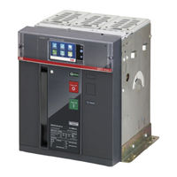
ABB SACE Emax E1.2 Instructions For Use Manual (36 pages)
Low voltage air circuit-breakers
Brand:
ABB
| Category:
Circuit breakers
| Size: 2.67 MB
Table of Contents
Table of Contents
3
Circuit Breakers Emax E1.2-E2.2-E4.2-E6.2
5
Contents
5
Organization of this Handbook
5
Intended Readership
5
Instructions
5
Integrated Informations
5
Introduction to Ekip Trip Units
6
Presentation
6
Families and Functionality
6
Accessorizing Modules
7
Ekip Touch Protection Trip Unit
8
Layout of the Interface
8
Components of the Interface
8
Signallings
9
Structure of the
9
Diagnosis Bar
9
Main Page
10
Start Page
10
Pages Details
11
Insertion of the Password
11
Description
11
Components of the Page
11
Setting the Parameters
12
Modifying a Parameter
12
Programming the Trip Unit
12
Protections
13
Operating Principle
13
Touch Protections
14
Availability (Performance)
14
Neutral
14
Summary Table of Basic Protections
15
Measuring Pro Protections
17
Availability (Performance)
17
Summary Table of Measuring Pro Protections
17
Availability (Performance)
18
Summary Table of Hi-Touch Protections
18
Hi-Touch Protections
18
Availability (Performance)
20
Summary Table for G Touch Protections
20
G Touch Protections
20
Availability (Performance)
22
Summary Table of G Hi-Touch Protections
22
G Hi-Touch Protections
22
External Toroid Protections
23
Touch Measurements
23
Ekip Measuring Measurements
23
Hi-Touch Measurements
23
Test
23
Self-Diagnosis
24
Alarms and Signals
24
Protections and Measurements
25
Programming Errors
26
Operating Features
27
Electrical Characteristics
27
Functional Characteristics
28
Additional Options Via Remote / Front Control
28
Default Parameters
28
Ekip Power Controller
28
Accessories
29
Preliminary Considerations
29
Introduction
29
Accessory Combination Tables
29
Disassembly Operations for Circuit Breakers E1.2
31
Disassembly Operations for Circuit Breakers E2.2-E4.2-E6.2
32
Wiring Diagrams
33
Electronic Accessories
33
Introduction
33
Ekip Measuring Modules
33
Ekip Synchrocheck Module
33
Ekip Signalling 4K Module
33
Ekip Signalling 2K Modules
33
Ekip Signalling 3T Modules
33
Ekip Com Modbus RTU Modules
33
Ekip Com Profibus DP Modules
33
Ekip Com Profinet Modules
34
Ekip Com Ethernet/Ip™ Modules
34
Ekip Com IEC 61850 Modules
34
Ekip Link Module
34
Ekip Com Hub Modules
34
Ekip Com Actuator Module
34
Other Accessories
34
Advertisement
ABB SACE Emax E1.2 Manual (4 pages)
Brand:
ABB
| Category:
Circuit breakers
| Size: 4.18 MB
Advertisement
Related Products
ABB SACE Emax Series
ABB SACE Emax
ABB Sace Emax UL Listed
ABB SACE Emax E1
ABB SACE Emax E6
ABB SACE SD-Pocket
ABB SACE Tmax XT
ABB SACE Tmax XT Series
ABB i-bus SA/S8.16.2.1
ABB SAS-W2.1F
ABB Categories
Industrial Equipment
Controller
Measuring Instruments
Battery Charger
DC Drives
More ABB Manuals
Login
Sign In
OR
Sign in with Facebook
Sign in with Google
Upload manual
Upload from disk
Upload from URL