
Related Manuals for Nav TV NTV-KIT558


Summary of Contents for Nav TV NTV-KIT558
- Page 1 3950 NW 120 Ave, Coral Springs, FL 33065 TEL 561-955-9770 FAX 561-955-9760 NNG-Ford V1 Navigation interface for FORD vehicles equipped with 8.4” MyTouch NTV-KIT558 NTV-DOC218...
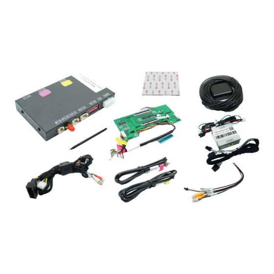
- Page 2 NTV-DOC218 SoftTouch Navigation System NTV-KIT558: FORD V1 NTV-KIT585: FORD V2 2011-2013 Ford Edge Installation Instructions Compatibility INSTALLATION PERFORMED ON FORD EDGE FOR REFERENCE ONLY! Parts Identification Page 1 Vehicle Preparation Page 2 n i t Installation Page 3 Parts Identification Item Qty.
- Page 3 NTV-DOC218 STOP – Install At Your Own Risk YOU MUST READ THESE WARNINGS AND NOTICE BEFORE PRODUCT HANDLING AND INSTALLATION! PRODUCT AND VEHICLE APPLICATION WARRANTY DISCLAIMER WARNING! The Navigation Electronic Components are sensitive to Electro-Static Discharge (ESD). DO NOT HANDLE THE NAVIGATION ELECTRONIC COMPONENTS WITHOUT PROPER ESD GROUNDING DURING INSTALLATION.
- Page 4 NTV-DOC218 WARNING To avoid dangerous distractions that may lead to an accident, the driver should never operate the system while the vehicle is in motion. Before installing this product, the seller should inform the end-user of proper use and compliance with the proper instructions and all state and federal laws.
- Page 5 NTV-DOC218 Installation Using even pressure, gently remove the trim strips Remove the four screws from both sides of the trim running from the center console to the dashboard by surrounding the vehicle’s shift lever. lifting them away. Remove the four screws attaching the factory radio Decouple the clips attaching the radio trim to the shift trim to the dashboard.
- Page 6 NTV-DOC218 Remove the radio trim from the vehicle making sure to Remove the four screws securing the factory touch unplug the wire harness for the air conditioning screen to the dashboard. Place them somewhere controls. where they will not be lost. Gently turn the touch screen unit towards the driver’s Gently remove these harnesses (Note: the large side of the vehicle to easily access the factory wiring...
- Page 7 NTV-DOC218 Gently lift the touch screen unit from the vehicle’s Remove the four screws from the backside of the dashboard. touch screen unit. Remove the four screws surrounding the outside of the Gently lift open the casing of the touch screen unit to touch screen unit.
- Page 8 NTV-DOC218 Using a small pry tool, gently release the large ribbon Gently remove the small ribbon cable from the board cable tab. as well. Remove the four screws securing the touch screen …this exposes the interface plug underneath. interface board to the touch screen unit…...
- Page 9 NTV-DOC218 Lift away the backside casing and route the LCD-IN Reapply the interface board making sure to properly and TP-IN harnesses through the opening. align the factory connector on its backside to the touch screen. Connect the ribbon cables from the navigation interface board to the touch screen interface board and re-secure the four mounting screws.
- Page 10 NTV-DOC218 Connect the ribbon cables from the touch screen unit Replace the touch screen unit making sure no ribbon to the newly installed navigation interface board. cables are pinched during the process. Secure the touch screen unit to its carriage frame by Remove the four screws securing the factory CD replacing the four previously removed screws.
- Page 11 NTV-DOC218 Remove the protective layer from the adhesive backing Mount the GPS antenna to the top-rear of the vehicle on the GPS speaker and attach it to the interior allowing it to attach using its magnetic base. dashboard frame behind the touch screen. Route the GPS antenna extensions harness to the front Connect the TP-IN and LCD-IN harness to the PINK of the vehicle above the headliner, down the...
- Page 12 NTV-DOC218 Connect the power harness from the vehicle interface Connect the speaker interface harness to the harness to the navigation control module. navigation control module. Find the threaded end of the GPS antenna and connect Connect the vehicle interface harness to the factory it to the navigation control module.
- Page 13 NTV-DOC218 Apply the included VHB tape to the bottom side of the Attach the navigation control module to the dashboard navigation control module. in the open cavity below the factory CD player. Attach the vehicle interface harness to the backside of Connect the TP-IN and LCD-IN harnesses previously the touch screen unit.
- Page 14 NTV-DOC218 If indoors, start the vehicle and move it outside so that the Replace the touch screen unit and factory CD player. GPS antenna has a clear view of the sky. Press the Make sure no wires are pinched in the process. mute/call decline button to switch from the factory interface to the iGo Navigation interface.
- Page 15 Ford Audio Integration Supplementary Manual This is a supplementary installation manual for FORD Navigation system with factory speaker integration. Please carefully refer to the main installation instruction for navigation system. WARRANTY DISCLAIMER NOTICE! Radio removal, disassembly, installation of Navigation Electronics, and Radio re-assembly / re-installation is the responsibility of the installer.
- Page 16 Ford Audio Integration Supplementary Manual (cont.) Components for audio integration: GPS Audio Box Wiring (FD-AUDSPK-02) Wiring (AUD-6PIN-01) Main Harness (same harness used in main install) Rear-LCD (connected to GPS box from main install) Steps: Connect both FD-AUDSPK-02 and AUD-6PIN-01 to GPS Audio Box Connect white power plug to Main Harness Insert green wire with pin to Main Harness (See figure 1) green wire from...
-
Page 17: Gps Monitor
WEAK /NO GPS SIGNAL? Tips to Improve GPS Antenna Signal if vehicle equipped Metallized Windshield* “GPS MONITOR Tools” Exit IGO MAP by press SHUT DOWN BUTTON Console> SETUP GPS MONITOR Locate the Antenna with minimum 5 bars in dark blue or Gray bar (Always suggest mounting the GPS antenna on the roof) Press “!”... - Page 18 PROPER GPS ANTENNA POSITION if vehicle equipped *Metallized Windshield SUV/Coupe Sedan TRUCK (Shown as Tundra) Alternatively, installer might choose to mount Antenna inside the headliner or inside vehicle using GPS monitor tools (see instruction). However, stay away from the windshield. * Windshields with metal particles can interfere with radio waves, dash-mount satellite radio receivers, and GPS receivers may be affected external transmitters and receivers may be required.
- Page 19 IGO PRIMO MAP PATH SETTING 1. Press Setup ‐> Navigate Setup 2. Press on the Folder Icon 3. Select the following path in Storage Card ‐> cyb_navi.exe 4. Press HOME button on the top left corner and press NAVIGATION 5. System should able to run into “IGO PRIMO”...