Konica Minolta bizhub 163 User Manual
Image controller
Hide thumbs
Also See for bizhub 163:
- Service manual (588 pages) ,
- User manual (346 pages) ,
- Quick manual (8 pages)
Table of Contents
Advertisement
Quick Links
Advertisement
Table of Contents

Related Manuals for Konica Minolta bizhub 163


Summary of Contents for Konica Minolta bizhub 163
- Page 1 User’s Guide [IC-206 Image Controller]...
- Page 2 163/211 is not sold in the USA market. Trademarks and copyright - KONICA MINOLTA, the KONICA MINOLTA logo, and The essentials of imaging are registered trademarks of KONICA MINOLTA HOLDINGS, INC. - PageScope and bizhub are registered trademarks or trademarks of KONICA MINOLTA BUSINESS TECHNOLOGIES INC.
- Page 3 person or organization contemplating export to obtain such a license before exporting. WITHIN THAT CONSTRAINT, permission to use, copy, modify, and distrib- ute this software and its documentation for any purpose and without fee is hereby granted, provided that the above copyright notice appear in all copies and that both that copyright notice and this permission notice appear in sup- porting documentation, and that the name of M.I.T.
- Page 4 the suitability of this software for any purpose. It is provided “as is” without express or implied warranty. THIS SOFTWARE IS PROVIDED “AS IS” AND WITHOUT ANY EXPRESS OR IMPLIED WARRANTIES, INCLUDING, WITHOUT LIMITATION, THE IMPLIED WARRANTIES OF MERCHANTIBILITY AND FITNESS FOR A PARTICULAR PURPOSE OpenLDAP Public License The OpenLDAP Public License...
- Page 5 Copyright 1999-2003 The OpenLDAP Foundation, Redwood City, California, USA. All Rights Reserved. Permission to copy and distribute verbatim copies of this document is granted. Cyrus SASL Copyright © 2001 Carnegie Mellon University. All rights reserved. Redistribution and use in source and binary forms, with or without modifica- tion, are permitted provided that the following conditions are met: 1.
- Page 6 this list of conditions and the following disclaimer in the documentation and/ or other materials provided with the distribution. Neither the name of Caldera Systems nor the names of its contributors may be used to endorse or promote products derived from this software without specific prior written permission.
- Page 7 THIS SOFTWARE IS PROVIDED BY THE OpenSSL PROJECT “AS IS” AND ANY EXPRESSED OR IMPLIED WARRANTIES, INCLUDING, BUT NOT LIM- ITED TO, THE IMPLIED WARRANTIES OF MERCHANTABILITY AND FIT- NESS FOR A PARTICULAR PURPOSE ARE DISCLAIMED. IN NO EVENT SHALL THE OpenSSL PROJECT OR ITS CONTRIBUTORS BE LIABLE FOR ANY DIRECT, INDIRECT, INCIDENTAL, SPECIAL, EXEMPLARY, OR CON- SEQUENTIAL DAMAGES (INCLUDING, BUT NOT LIMITED TO, PROCURE- MENT OF SUBSTITUTE GOODS OR SERVICES;...
- Page 8 3. All advertising materials mentioning features or use of this software must display the following acknowledgement: “This product includes cryptographic software written by Eric Young (eay@cryptsoft.com)” The word ‘cryptographic’ can be left out if the rouines from the library be- ing used are not cryptographic related :-).
-
Page 9: About Pagescope Web Connection
- This User’s Guide may not be reproduced in part or in full without permis- sion. - Konica Minolta Business Technologies, Inc. will not be held liable for any incidents caused by using this User’s Guide. - Information included in this User’s Guide is subject to change without no- tice. -
Page 10: Software End User License Agreement
Software, and any and all rights and title to the Software and any copy made from it are retained by Konica Minolta or Koni- ca Minolta Licensor. In no event, this Agreement shall be deemed to assign any copyright and/or any intellectual property rights of the Software from Konica Minolta or Konica Minolta Licensor to you. - Page 11 (1) If the Software is furnished on CD-ROM(s) or other tangible object that is used for storage of digital data (hereinafter collectively “Storage Medium”), Konica Minolta warrants the Storage Medium to be free from the defects in material and workmanship under normal use, for a period of ninety (90) days from the date of delivery to you.
- Page 12 6. GOVERNING LAW This Agreement shall be governed by the laws of Japan. 7. SEVERABILITY In the event that any part or parts of this agreement shall be held illegal or null and void by any court or administrative body of competent jurisdiction, such determination shall not effect the remaining parts of this agreement and they shall remain in full force and effect as if such part or parts determined illegal or void had not been included.
-
Page 13: Table Of Contents
Contents Introduction About PageScope Web Connection ...x-8 Copyright ...x-8 Software End User License Agreement ...x-9 Contents ...x-12 Explanation of manual conventions ...x-20 Getting ready Overview ...1-1 Names of control panel parts and their functions ...1-2 Entering text ...1-7 Changing the input mode ...1-7 Key operation ...1-7 Text input example ...1-8 Correcting text and input precautions ...1-11... - Page 14 Installing the printer driver by using the Add Printer Wizard ... 2-15 Connecting to a computer through a network ... 2-15 Installing using the Add Printer Wizard on Windows XP/ Server 2003 ... 2-16 Installing using the Add Printer Wizard on Windows Vista ... 2-20 Installing using the Add Printer Wizard on Windows 2000 ...
- Page 15 Specifying printer driver settings Printer driver settings dialog box ...4-1 Displaying the settings dialog box ...4-1 Printing Preferences dialog box ...4-3 Properties dialog box ...4-6 Device Options tab ...4-7 Device Options ...4-8 Memory ...4-8 Common operations ...4-9 Common items ...4-9 Easy Set ...4-10 Setup tab ...4-12 Orientation ...4-12...
- Page 16 Control panel operations for printing functions Printing operations ... 5-1 Printer indicator ... 5-1 Starting the print operation ... 5-2 Canceling a print job ... 5-3 Using the manual bypass tray ... 5-6 Power Save mode ... 5-8 Network scanning Scan to E-mail ...
- Page 17 LDAP SETTING ...7-35 Specifying the LDAP server address ...7-35 Specifying the LDAP port number ...7-37 Selecting the SSL setting ...7-38 Specifying the search base ...7-39 Specifying the attribute setting ...7-39 Selecting the search method ...7-40 Specifying the LDAP search timeout ...7-41 Specifying the maximum number of search items ...7-41 Selecting the authentication method ...7-42 Specifying the LDAP account name ...7-43...
- Page 18 Changing the document scanning density ... 9-23 When “TEXT/PHOTO” or “TEXT” was selected ... 9-23 When “PHOTO” was selected ... 9-26 Specifying the default scanning settings ... 9-28 Selecting the resolution ... 9-28 Selecting the file format ... 9-29 Selecting the compression encoding method ... 9-30 If the memory becomes full while scanning documents ...
- Page 19 11.7 User mode ...11-10 User mode tabs ...11-10 System tab — Summary ...11-11 System tab — Details — Input Tray ...11-12 System tab — Details — Output Tray ...11-13 System tab — Details — ROM Version ...11-14 System tab — Details — Interface Information ...11-15 System tab —...
- Page 20 When “E-Mail” or “LDAP Search” is selected: ... 11-56 When “FTP Server Address” is selected: ... 11-57 Scan tab — Group Dial Setting ... 11-58 Scan tab — Fax Configuration ... 11-61 Scan tab — Downloading/Uploading Destination List ... 11-63 Upload ...
-
Page 21: Explanation Of Manual Conventions
Explanation of manual conventions x-20 IC-206... -
Page 22: Getting Ready
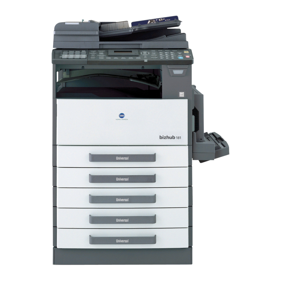
Getting ready Getting ready This chapter provides information that is important to know before this de- vice is used. Overview By installing image controller IC-206, this machine can be used as a net- work-compatible PCL printer. In order to use the PCL printing functions, in- stall onto the computer the PCL printer driver included with the image controller. -
Page 23: Names Of Control Panel Parts And Their Functions
Names of control panel parts and their functions Part name [Power Save] key [Mixed Original] key/indicator [Simplex/Duplex] key/indicator Display [+], [,], [*] and [)] keys [OK] key [Printer] key/indicator [Access] key [Speed Dial] key [Phone Book] key [Back] key “Caution” indicator [Density] key Description Press to enter Power Save mode. - Page 24 Getting ready Part name [Quality] key [Zoom] key [Paper] key [Function] key/indicator [Finishing] key/indicator [Combine Original] key/indicator [Confirm] key [Utility] key [Mode Memory] key IC-206 Description Press to select “TEXT”, “PHOTO” or “TEXT/ PHOTO” as the document quality. Press to specify whether to enlarge or reduce the image when copying.
- Page 25 Part name [Fax] key/indicator [Scan] key/indicator [Copy] key/indicator [123/ABC] key [Reset] key [Interrupt] key/indicator Description Press to enter Fax mode. The indicator on the key lights up in green to indicate that the ma- chine is in Fax mode. Press to enter Scan mode. The indicator on the key lights up in green to indicate that the machine is in Scan mode.
- Page 26 Getting ready Part name [Clear/Stop] key [Start] key/indicator Keypad IC-206 Description • Press to clear the entered number. • Press to stop a continuous copy operation. • Press to stop the transmission/reception of the fax. • Press to stop the print job from the compu- ter.
- Page 27 Part name Auto RX indicator [Memory TX] key/indicator [On Hook] key [Redial/Pause] key One-touch dial keys Switching plate Description This indicator lights up when the automatic re- ception function is selected. Press this key to select the memory transmis- sion function. This indicator lights up in green when the memory transmission function is se- lected.
-
Page 28: Entering Text
Getting ready Entering text Follow the procedure described below to enter text when specifying the user name or programming one-touch dial keys with the recipient name. Changing the input mode Each press of the [123/ABC] key switches between number input mode and letter input mode. -
Page 29: Text Input Example
Keypad key Available characters [1…] Text input example To enter the name “Office 01”: Press the [123/ABC] key until input mode [A…] is selected. * The cursor (_) flashes alternately in the display with the character at its cur- rent location. [A…] (space) 0 + &... - Page 30 Getting ready IC-206 Press the [3] key 7 times. Press the [)] key. Press the [3] key 7 times. Press the [4] key 7 times. Press the [2] key 7 times.
- Page 31 1-10 Press the [3] key 6 times. Press the [0] key. Press the [123/ABC] key. Press the [0] key. Getting ready IC-206...
-
Page 32: Correcting Text And Input Precautions
Getting ready Correcting text and input precautions To delete a part of the entered text: Press the [*] or [)] key to move the cursor (_) below the character to be de- leted, and then press the [Clear/Stop] key. To change entered characters: Press the [*] or [)] key to move the cursor (_) below the character that you wish to change, and then enter the new character. -
Page 33: Connecting To A Local Area Network (Lan)
Connecting to a local area network (LAN) This machine can transmit with the TCP/IP protocol on a LAN. Therefore, this machine must be connected to the LAN with a network cable. Connecting the network cable Insert one plug on the network cable into the network port (LAN) on the left side of the machine, and then insert the other plug into an available port on the network hub. -
Page 34: Installing The Printer Driver
Installing the printer driver Installing the printer driver Descriptions on connecting the machine to a computer and installing the printer driver are provided below. System requirements The following environment is required so that the printer driver can be used. Element Processor Operating Server... -
Page 35: Making Connections And Installing The Driver
Making connections and installing the driver Connecting to a computer This machine can be connected to a computer using any of the following connection methods. Connecting to a USB port In the following procedure, the machine is connected directly to the compu- ter by using a USB cable. -
Page 36: Procedures For Making Connections And Installing The Driver
Installing the printer driver Connecting to the network In the following procedure, the machine is connected directly to the compu- ter by using a network cable. When the machine is connected to a network, use the Add Printer Wizard to install the printer driver. - Page 37 Connection Supported operating method systems USB port con- Windows XP/Windows nection Server 2003/Windows Vista/Windows 2000/ Windows Me Network con- Windows XP/Windows nection Server 2003/Windows Vista/Windows 2000/ Windows Me/Windows 98 SE Note When installing using Plug and Play, the TWAIN driver for scanning is also installed with the printer driver.
-
Page 38: General Operation For Driver Installation
Installing the printer driver General operation for driver installation The driver is installed according to the following general operation. Installation using Plug and Play When installing the driver by using Plug and Play, the installation procedure differs depending on the operating system. With Windows Me Install the USB printing support driver. -
Page 39: Installation Using The Add Printer Wizard
Installation using the Add Printer Wizard When installing the printer driver by using the Add Printer Wizard, the instal- lation procedure is the same for all operating systems. With Windows 98 SE Installing the printer driver With Windows Me With Windows XP, Windows Server 2003, Win- dows Vista and Windows 2000... -
Page 40: Installing The Printer Driver By Using Plug And Play
Installing the printer driver Installing the printer driver by using Plug and Play Connecting to the computer’s USB port When this machine is connected to a computer with a USB cable, Plug and Play detects the device, and then installation of the necessary drivers begins. Start Windows, and then insert the CD-ROM/DVD into the computer’s CD-ROM drive. -
Page 41: Installing Using Plug And Play On Windows Xp/Server 2003
Installing using Plug and Play on Windows XP/Server 2003 Note If the driver is installed using Plug and Play, first the TWAIN driver for scanning is installed, and then installation of the printer driver begins. The procedure described in this manual is for the installation of the TWAIN driver, then the printer driver. - Page 42 Installing the printer driver Select “Include this location in the search:” and then specify the follow- ing folder on the CD-ROM as the location where the driver is saved. – Folder to be specified: \Driver\WIN2K_XP\English – With 64-bit operating systems, select “Driver\WinXP64\English”. –...
-
Page 43: Installing Using Plug And Play On Windows Vista
Installing using Plug and Play on Windows Vista Note If the driver is installed using Plug and Play, first the TWAIN driver for scanning is installed, and then installation of the printer driver begins. The procedure described in this manual is for the installation of the TWAIN driver, then the printer driver. - Page 44 Installing the printer driver Select “Include subfolders”, and then specify the following folder on the CD-ROM as the location where the driver is saved. – Folder to be specified: \Driver\WinVista\English – With 64-bit operating systems, select “\Driver\WinVista64\English”. – The folder can be selected after clicking the [Browse] button. Click the [Next] button.
-
Page 45: Installing Using Plug And Play On Windows 2000
Installing using Plug and Play on Windows 2000 Note If the driver is installed using Plug and Play, first the TWAIN driver for scanning is installed, and then installation of the printer driver begins. The procedure described in this manual is for the installation of the TWAIN driver, then the printer driver. -
Page 46: Installing Using Plug And Play On Windows Me
Installing the printer driver Installing using Plug and Play on Windows Me Note If the driver is installed using Plug and Play, first the TWAIN driver for scanning is installed, next the USB printing support driver is installed, and then installation of the printer driver begins. The procedure described in this manual is for the installation of the TWAIN driver, the USB printing support driver, then the printer driver. -
Page 47: Reinstalling The Printer Driver By Using Plug And Play
Click the [Finish] button. – To change the printer name, type in the new name. – To set this machine as the default, select “Yes”. A dialog box appears, indicating that the installation is finished. Click the [Finish] button. This completes the installation of the printer driver. Reinstalling the printer driver by using Plug and Play Uninstall the printer driver while the machine is not connected to the computer or while they are connected but the machine is turned off,... -
Page 48: Installing The Printer Driver By Using The Add Printer Wizard
Installing the printer driver Installing the printer driver by using the Add Printer Wizard Connecting to a computer through a network If this machine is connected to a computer through a network, the printer driver can be installed either before or after the connection is established. Use the network cable to connect this machine to the computer. -
Page 49: Installing Using The Add Printer Wizard On Windows Xp/Server 2003
Installing using the Add Printer Wizard on Windows XP/Server 2003 Note When using a USB cable to connect this machine to the computer, turn off this machine, and then install the printer driver. When the machine is turned on, Plug and Play causes the Add New Hardware Wizard to ap- pear. - Page 50 Installing the printer driver – If “Printer Tasks” does not appear, double-click the “Add Printer” icon. The Add Printer Wizard starts up. Click the [Next] button. Select “Local printer attached to this computer”, and then click the [Next] button. – The “Automatically detect and install my Plug and Play printer”...
- Page 51 Click the [Browse] button, select “Driver\WIN2K_XP\English” on the CD-ROM, and then click the [Open] button. – With 64-bit operating systems, select “Driver\WinXP64\English”. Click the [Open] button again. Check the path in the “Copy manufacturer’s files from” box, and then click the [OK] button. 2-18 Installing the printer driver IC-206...
- Page 52 Installing the printer driver Select the printer to be installed, and then click the [Next] button. Continue selecting the appropriate settings according to your environ- ment and clicking the [Next] button until the [Finish] button appears. – For a network connection, perform a test print after specifying the network settings.
-
Page 53: Installing Using The Add Printer Wizard On Windows Vista
Installing using the Add Printer Wizard on Windows Vista Note When using a USB cable to connect this machine to the computer, turn off this machine, and then install the printer driver. When the machine is turned on, Plug and Play causes the Found New Hardware wizard to ap- pear. - Page 54 Installing the printer driver – In order to print on a network, the connection port must be set up as a network port. Since the port settings can be specified after in- stallation, this procedure describes how to install the printer driver for a local connection.
- Page 55 Select the printer to be installed, and then click the [Next] button. Continue selecting the appropriate settings according to your environ- ment and clicking the [Next] button until the [Finish] button appears. – If the User Account Control dialog box appears, click the [Continue] button.
-
Page 56: Installing Using The Add Printer Wizard On Windows 2000
Installing the printer driver Installing using the Add Printer Wizard on Windows 2000 Note When using a USB cable to connect this machine to the computer, turn off this machine, and then install the printer driver. When the machine is turned on, Plug and Play causes the Add New Hardware Wizard to ap- pear. - Page 57 Select “LPT1:” beside “Use the following port”, and then click the [Next] button. Click the [Have Disk] button. Click the [Browse] button, select “Driver\WIN2K_XP\English” on the CD-ROM, and then click the [Open] button. Click the [Open] button again. Check the path in the “Copy manufacturer’s files from” box, and then click the [OK] button.
- Page 58 Installing the printer driver Select the printer to be installed, and then click the [Next] button. Continue selecting the appropriate settings according to your environ- ment and clicking the [Next] button until the [Finish] button appears. – For a network connection, perform a test print after specifying the network settings.
-
Page 59: Installing Using The Add Printer Wizard On Windows Me/98 Se
Installing using the Add Printer Wizard on Windows Me/98 SE Note When using a USB cable to connect this machine to the computer, turn off this machine, and then install the printer driver. When the machine is turned on, Plug and Play causes the Add New Hardware Wizard to ap- pear. - Page 60 Installing the printer driver Click the [Have Disk] button. Click the [Browse] button, select “Driver\Win98_ME\English” on the CD-ROM, and then click the [OK] button. Click the [OK] button again. Check the path in the “Copy manufacturer’s files from” box, and then click the [OK] button.
-
Page 61: Reinstalling The Printer Driver By Using The Add Printer Wizard
After installation is complete, check that the icon for the installed print- er appears in the Printers window, and then remove the CD-ROM from the CD-ROM drive. This completes the installation of the printer driver. Reinstalling the printer driver by using the Add Printer Wizard Uninstall the printer driver while the machine is not connected to the computer or while they are connected but the machine is turned off, and then restart the computer. -
Page 62: Uninstalling The Printer Driver
Installing the printer driver Uninstalling the printer driver Note With Windows XP, Server 2003, Vista and 2000, log on as a user with Ad- ministrator privileges to delete the printer driver. For details on deleting the TWAIN driver, refer to the User’s Guide for the TWAIN driver. - Page 63 – If Windows 2000, XP or Server 2003 is being used, continue with step 7. – If Windows Vista is being used, continue with step 6. When a message appears, requesting confirmation to continue delet- ing, select “Remove driver and driver package.”, and then click the [OK] button.
-
Page 64: Deleting Related Files
Installing the printer driver Deleting related files Even after the printer driver is deleted from the Printers and Faxes window, device information files remain on the computer. When using Windows XP/Server 2003, it may not be possible to overwrite the driver, even if the same version of the printer driver is reinstalled. If the printer driver cannot be upgraded, even by reinstalling it, follow the proce- dure described below to also delete the device information files. - Page 65 Installing the printer driver 2-32 IC-206...
-
Page 66: Network Printing
Network printing Network printing This chapter provides descriptions of the procedures for installing the image controller and using this machine as a network printer. Selecting the network printing method When the image controller is installed, various network printing methods are possible. - Page 67 LPR printing / PORT9100 printing Compatible operating systems: Windows 2000 / Windows XP / Windows Sever 2003/Windows Vista LPR printing - Using the LPR (line printer remote) print service, the computer and this machine are connected over a network. - The LPR print service is supported by the operating system as the stand- ard.
- Page 68 Network printing IPP printing Compatible operating systems: Windows 2000 / Windows XP / Windows Sever 2003/Windows Vista Access IPP printing - Using the IPP (Internet printing protocol) print service, the computer and this machine are connected over a network. - The IPP print service is supported by the operating system as the stand- ard.
-
Page 69: When Using A Netware Environment (Netware Server And Windows Client)
When using a NetWare environment (NetWare server and Windows cli- ent) In a NetWare environment, the Windows computer is used as a NetWare cli- ent, and printing with this machine is possible through the NetWare server. Connecting the NetWare server and this machine When connecting the NetWare server and this machine over a network, the following methods are supported. -
Page 70: Checking The Setup
Network printing Checking the setup This section provides an overview of the setup procedure that is required for each network printing method. Peer-to-peer printing Connect the network cable. (Refer to “Connecting to a local area net- work (LAN)” on page 1-12.) From the machine’s control panel, specify the IP address, subnet mask and default gateway. -
Page 71: Lpr/Port9100 Printing
LPR/PORT9100 printing Connect the network cable. (Refer to “Connecting to a local area net- work (LAN)” on page 1-12.) From the machine’s control panel, specify the IP address, subnet mask and default gateway. (Refer to “Specifying an IP address” on page 3-9.) Print the settings information, and then check the settings. -
Page 72: Ipp Printing
Network printing IPP printing Connect the network cable. (Refer to “Connecting to a local area net- work (LAN)” on page 1-12.) From the machine’s control panel, specify the IP address, subnet mask and default gateway. (Refer to “Specifying an IP address” on page 3-9.) Print the settings information, and then check the settings. -
Page 73: Netware Server/Client (Except Ndps)
NetWare server/client (except NDPS) Connect the network cable. (Refer to “Connecting to a local area net- work (LAN)” on page 1-12.) Specify the necessary settings for connecting this machine to a Net- Ware server. (Refer to “Connecting the computer and this machine over a network”... -
Page 74: Specifying An Ip Address
Network printing Specifying an IP address The following procedure describes how to assign the IP address to the ma- chine from the control panel. Note The IP address setting should be specified according to instructions from the network administrator. The IP address setting is specified in Utility mode by the administrator. Press the [Utility] key in the control panel. - Page 75 Type in the administrator access code, and then press the [OK] key. – The manufacturer’s default setting is “000000”. – If the code was incorrectly entered, press the [Clear/Stop] key to erase the number, and then type it in correctly. Press the [,] or [+] key until “NETWORK SETTING”...
- Page 76 Network printing Press the [,] or [+] key until “AUTO” or “SPECIFY” is selected, and then press the [OK] key. – If “AUTO” was selected, the IP address will automatically be ob- tained from the DHCP server. After the message “ACCEPTED” ap- pears, the “NETWORK SETTING”...
- Page 77 Using the keypad, type in the gateway. – For the gateway, consult with the network administrator. – If the number was incorrectly entered, press the [Clear/Stop] key to erase it, and then type it in correctly. Press the [OK] key. The message “ACCEPTED”...
-
Page 78: Printing The Settings Information
Network printing Printing the settings information Print the settings information to be able to check the settings. From the control panel, press the [Confirm] key. The “CONFIRM MODE” menu appears. Press the [,] or [+] key until “PRINT REPORT” is selected, and then press the [OK] key. - Page 79 Press the [OK] key. After the message “PRINTING” appears, the settings information is printed. Note If “PCL FONT LIST” is selected, the list of printer fonts can be viewed. 3-14 Network printing IC-206...
-
Page 80: Connecting The Computer And This Machine Over A Network
Network printing Connecting the computer and this machine over a network Specify the settings necessary for connecting the computer and this ma- chine over the network and sending a print job through the network from the computer. The following connection procedures are described in this section. - Peer-to-peer printing –... -
Page 81: Lpr Printing
Click the Details tab, and then click the [Add Port] button. Select “Other”, and then select “Peer2Peer” from the “list of port types”. Click the [OK] button. Type in the IP address of this machine, and then click the [OK] button. Click the [Apply] or the [OK] button. -
Page 82: Port9100 Printing
Network printing Select “Custom”, and then click the [Settings] button. Select “LPR” in the protocol group box, type the queue name in the “Queue Name” box of the “LPR Settings” group box, and then click the [OK] button. – Type in a queue name that begins with a letter (for example, “print”). Click the [Next] button. -
Page 83: Ipp Printing
Click “Properties” to open the Properties dialog box. Click the Ports tab, and then click the [Add Port] button. In the Printer Ports dialog box, select “Standard TCP/IP Port”, and then click the [New Port] button. After the Add Standard TCP/IP Printer Port Wizard starts up, click the [Next] button. -
Page 84: Checking Ipp-Related Settings From Pagescope Web Connection
Network printing Reminder Before specifying settings, check that the following preparations have been completed. The computer can communicate using the TCP/IP protocol. This machine can communicate using the TCP/IP protocol. The printer driver is installed on the computer. (For details on installing the PCL driver, refer to “Installing the printer driv- er by using the Add Printer Wizard”... -
Page 85: Ipp Printing Connections
IPP printing connections Establish the IPP printing connection. The IPP printing connection must be set up starting from the installation of the printer driver. (For details on install- ing the PCL driver, refer to “Installing the printer driver by using the Add Print- er Wizard”... -
Page 86: Connecting The Ipp Printing Netware Server And This Machine
Network printing Connecting the IPP printing NetWare server and this machine Connecting the NetWare server and this machine NetWare version NetWare 4.x NetWare 5.x / 6 Specifying the NetWare 4.x/5.x/6 print server mode settings Log on with Administrator privileges. Start up NWadmin. Select the print server system or category container, and then select “Print service quick setup”... - Page 87 Parameter Password Retype Preferred File Server Preferred NDS Tree Print Queue Scan Rate* Mode* Printer Number Connection Mode After changing the settings for parameters marked with an asterisk (*), turn the machine off, then on again. Specifying the NetWare 4.x/5.x/6 remote printer mode settings Log on with Administrator privileges.
- Page 88 Network printing Parameter NetWare Configuration* Frame Type* Print Server Name NDS Context Name Print Server Password Password Retype Preferred File Server Preferred NDS Tree Print Queue Scan Rate* Mode* Printer Number Connection Mode After changing the settings for parameters marked with an asterisk (*), turn this machine off, then on again.
- Page 89 Creating an NDPS printer agent Log on with Administrator privileges. Start up NWadmin. Right-click the name of the organization or department container where you want to create the printer agent, and then select “NDPS printer”. In the “NDPS Printer Name” box, type the printer name. In the “Printer Agent Source”...
-
Page 90: Specifying Printer Driver Settings
Specifying printer driver settings Specifying printer driver settings Descriptions on the printer driver settings available when printing from a computer are provided below. Printer driver settings dialog box Displaying the settings dialog box Select the printer in the Printers and Faxes window (the Printers window in Windows Vista/2000/Me/98 SE), and then display the printer driver settings dialog box. - Page 91 The following printer driver settings dialog box appears. Note To change the settings for each job to be printed, click the [Properties] button (or the [Preferences] button) in the Print dialog box, which appears when “Print” is clicked in the application. The settings specified in the di- alog box displayed from the Print dialog box are only applied temporarily, and the settings return to those in the printer driver settings dialog box when the application is exited.
-
Page 92: Printing Preferences Dialog Box
Specifying printer driver settings Printing Preferences dialog box Printing settings can be specified from the printer driver settings dialog box. Note To display the Printing Preferences dialog box in Windows XP/Server 2003/Vista/2000, right-click the icon for the installed printer in the Print- ers and Faxes window (or the Printers window), and then click “Printing Preferences”. - Page 93 Item Setup Orientation Original Size [Edit Custom] button Output Size Zoom Copy Collate Paper Source Paper Type Output Method Layout Combination [Combination Details] button Double Sides Binding Position Per Page Set- Front Cover Page ting Front Cover Paper Source Media Type Back Cover Page Back Cover Paper Source...
- Page 94 Specifying printer driver settings Item Quality Resolution [Adjustment] button [Font Settings] button Toner Save About IC-206 Description Specify the print resolution. Specify the brightness and contrast. Select whether TrueType fonts or printer fonts are used during printing. Select whether or not to print while controlling toner consumption.
-
Page 95: Properties Dialog Box
Properties dialog box Installed options can be selected from the Properties dialog box for the print- er driver. Reminder If the options installed on the machine are not specified from the Device Options tab, the functions available with the option cannot be used from the printer driver. -
Page 96: Device Options Tab
Specifying printer driver settings Device Options tab Specify whether or not options are installed so that the options installed on the machine can be used from the printer driver. Reminder If the options installed on the machine are not specified from the Device Options tab, the functions available with the option cannot be used from the printer driver. -
Page 97: Device Options
Device Options Specify the settings for the installed paper drawers. From the “Device Options” list, double-click the names of installed paper drawers to specify that it is installed. Double-click the name again to return the setting to “Not Installed”. Memory Specify the size of the installed memory. -
Page 98: Common Operations
Specifying printer driver settings Common operations This section contains descriptions of buttons and functions common to all tabs of the dialog box. The actual buttons may appear differently depending on the operating system. Common items Button [OK] button [Cancel] button [Apply] button [Help] button Preview... -
Page 99: Easy Set
Button Easy Set Easy Set The currently specified settings can be registered as a program to be re- called later when you wish to use those settings again. Change the driver settings on the Setup and Layout tabs. In the “Easy Set” box, type the name of the program. Click the [Save] button. - Page 100 Specifying printer driver settings Note To recall a registered program, select it from the list. To change the name of the registered program, select the program from the list, and then type in the new program name. The button changes to the [Rename] button.
-
Page 101: Setup Tab
Setup tab From the Setup tab, settings can be specified for the document and paper to be printed on. The number of copies to be printed and the orientation of the printed image can also be specified. Orientation Select whether to print the document in the portrait or landscape orientation. 4-12 Specifying printer driver settings ABCD... -
Page 102: Original Size
Specifying printer driver settings Original Size From the drop-down list, click the paper size for the document to select it. The following standard paper sizes are available. Setting Letter Legal 11 × 17 Env.Com10 Env.DL Env.C6Envelope FLS 8 1/4 × 13 FLS 8 1/2 ×... -
Page 103: Edit Custom
Edit Custom A paper size that does not appear in the list can be registered as a custom size. Click the [Edit Custom] button on the Setup tab. The Custom Size Settings dialog box appears. Click the [New] button. The Custom Size Settings dialog box enlarges to display settings for specifying the paper size. - Page 104 Specifying printer driver settings In the “Dimensions” group box, specify the width and length of the pa- per. – To change the units for specifying the paper size, select the desired setting in the “Unit” group box. Click the [OK] button in the lower-right corner of the Custom Size Set- tings dialog box.
-
Page 105: Output Size
Output Size Select the size of paper that is to be used for printing. The available standard paper sizes are same as those available in the “Orig- inal Size” list. If the paper size is different from the size selected in the Original Size list, the document image will be printed enlarged or reduced so that it fits in the se- lected paper size. -
Page 106: Zoom
Specifying printer driver settings Zoom Specify the enlargement or reduction ratio to be used for printing. Select “Manual”, and then type in a number between 25% and 400%, or click the arrows to specify a setting. Note If any setting other than “Same as Original Size” is selected in the “Output Size”... -
Page 107: Collate
Collate When printing multiple copies of the same document, select whether the en- tire document is printed one copy at a time or whether the specified number of copies are printed one page at a time. When the “Collate” check box is selected, the entire document is printed one copy at a time. -
Page 108: Paper Source
Specifying printer driver settings Paper Source Select the paper drawer loaded with the paper. If “Auto” is selected, the paper drawer loaded with paper of the size specified in the “Output Size” list is used. The available settings differ depending on the options that are installed. Settings: Tray 1, Tray 2 through Tray 5 (options), Bypass Note If “Hagaki”... -
Page 109: Output Method
Output Method Select the printing method. Not only can data be printed directly, but “Secure Print” is also available, which requires a password for printing from this machine. Settings: Print, Secure Print Note “Secure Print” is available only if the optional expanded memory unit is installed. -
Page 110: Specifying Secure Printing From The Printer Driver
Specifying printer driver settings Specifying secure printing from the printer driver Click the Setup tab. From the “Output Method” drop-down list, select “Secure Print”. A screen appears, allowing you to type in the password. Type in the password, and then click the [OK] button. –... - Page 111 Check that the key icon appears in the upper-right corner of the screen. – The key icon appears if the memory contains a secure print docu- ment. Press the [Access] key. When “PASSWORD: – – – –” appears, type in the password. –...
- Page 112 Specifying printer driver settings Check that the document can be printed. If the password is correct, the following screen appears, and the job is printed. Note If there are multiple secure print jobs with the same password, all of those secure print jobs are printed.
-
Page 113: Layout Tab
Layout tab From the Layout tab, select the number of document pages to be printed on a single sheet of paper. 4-24 Specifying printer driver settings IC-206... -
Page 114: Combination
Specifying printer driver settings Combination Multiple document pages can be printed together on a single sheet of paper. Use combined printing to economize on the number of printed pages. From the drop-down list, select the number of pages to be printed on a single sheet of paper. -
Page 115: Combination Details
Combination Details Click the [Combination Details] button to specify the printing order and whether or not to print page outlines. Combination Order Border Line 4-26 Specifying printer driver settings Select the number of pages to be printed on a single sheet of paper. This is the same setting selected in the “Combination”... -
Page 116: Double-Sided Printing
Specifying printer driver settings Double-sided printing Document pages can be printed on both sides of the paper. Print on both sides when binding a multi-page document. Click the Layout tab. From the “Double Sides” drop-down list, select “Double Sided”. Note From the “Binding Position”... -
Page 117: Per Page Setting Tab
Per Page Setting tab From the Per Page Setting tab, specify whether or not a cover page is added. Front Cover Page/Back Cover Page Select whether or not a cover page is added and whether or not a document page is printed on the cover page. Settings: None Blank... -
Page 118: Watermark Tab
Specifying printer driver settings Watermark tab From the Watermark tab, specific text can be printed in the background as a watermark. Watermark Select From the Watermark Select list, select the text. A setting is available for specifying whether the watermark is printed on all pages or only on the first page. -
Page 119: Creating A New Watermark
Creating a new watermark A new watermark can be registered. Click the Watermark tab. Click the [New] button. The New dialog box appears. In the “Watermark Text” box, type in the text to be used as the water- mark. – A maximum of 20 characters can be entered for the text. - Page 120 Specifying printer driver settings – Offset from Center: Specify the horizontal and vertical positions for the location where the text is to be printed. Settings between -100 and 100 can be specified. – The position can also be changed by using the sliders below and to the right of the preview image.
-
Page 121: Editing A Watermark
Editing a watermark A registered watermark can be edited to change the text, size and position. Click the Watermark tab. From the list, select the watermark to be edited. Click the [Edit] button. The Edit dialog box appears. Specify the desired settings. –... - Page 122 Specifying printer driver settings – The position can also be changed by using the sliders below and to the right of the preview image. Horizontal direction: Reducing the number moves the text to the left. Click the [OK] button. The watermark is changed. Note To delete a registered watermark, select the watermark from the list, and then click the [Delete] button.
-
Page 123: Quality Tab
Quality tab From the Quality tab, settings for the print quality can be specified. Resolution From the drop-down list, specify the print resolution. 4-34 Specifying printer driver settings IC-206... -
Page 124: Adjustment
Specifying printer driver settings Adjustment Click the [Adjustment] button to specify the brightness and contrast. Brightness Contrast IC-206 Adjust the brightness of the printed image. A setting between -50 and 50 can be specified. The larger the number, the higher the contrast and the more distinct the image. -
Page 125: Font Settings
Font Settings Settings can be specified to replace the TrueType fonts used in Windows with the printer fonts installed on this machine. Font Settings Click the Quality tab. Click the [Font Settings] button. Specify the desired settings. – Use Printer Fonts: Select this setting to replace the TrueType fonts with the printer fonts according to the Font Substitutions table. - Page 126 Specifying printer driver settings Specifying the Font Substitutions table Click the [New] button. – To make changes, select the row containing the font to be changed, and then click the [Edit] button. Select the TrueType font to be replaced at the top, and then select the printer font to be used at the bottom.
-
Page 127: Toner Save
Note To delete specified replacements, select the row for the font, and then click the [Delete] button. Toner Save Select whether or not to print while controlling toner consumption. This can be used when printing test pages. 4-38 Specifying printer driver settings IC-206... -
Page 128: Control Panel Operations For Printing Functions
Control panel operations for printing functions Control panel operations for printing functions Descriptions on the printing operations that can be performed from the con- trol panel of the machine are provided below. Printing operations The default mode of the machine is the Copy mode. Normally, when printing is performed from a connected computer, printing begins automatically. -
Page 129: Starting The Print Operation
Starting the print operation Normally, printing begins when printing is performed from a connected com- puter. - Normally, when printing is performed from a connected computer, print- ing begins automatically. - If a print operation is performed from a connected computer while the machine is copying, printing begins automatically when no copy opera- tion is performed for 30 seconds. -
Page 130: Canceling A Print Job
Control panel operations for printing functions Canceling a print job Printing of a print job can be canceled from the control panel of the ma- chine’s control panel. However, a print job can only be canceled from the control panel while the machine is in Printer mode. Check that the Printer indicator is flashing or is lit, and then press the [Printer] key. - Page 131 Press the [+]or [,] key to select “YES”, and then press the [OK] key. – To continue printing, select “No”. – If no key is pressed within five seconds, printing continues. “ACCEPTED” appears in the display and the print job is canceled. Control panel operations for printing functions IC-206...
- Page 132 Control panel operations for printing functions Note If any of the following messages appear in the display, the print job can also be canceled by repeating steps 2 and 3 from the procedure de- scribed above. PAPER EMPTY PAPER JAM PAPER SIZE ERROR RESET PAPER NO SUITABLE PAPER...
-
Page 133: Using The Manual Bypass Tray
Using the manual bypass tray Follow the procedure described below when using the manual bypass tray to print one page at a time. From the computer, display the Setup tab for the printer driver, and then select “Bypass” in the “Paper Source” list (page 4-19). Perform the print operation from the computer. - Page 134 Control panel operations for printing functions – Slide the paper guides to fit the size of paper being load- Repeat step 3 as often as necessary until printing of the document is finished. Note Be sure to load the paper into the manual bypass tray after the print op- eration is performed from the computer.
-
Page 135: Power Save Mode
Power Save mode If print data is received while the machine is in Power Save mode, the mode is canceled. When print data is received, the data is printed after the machine has finished warming up. Control panel operations for printing functions IC-206... -
Page 136: Network Scanning
Network scanning Network scanning Using the network scanning function, scan data can be sent to a recipient’s computer by e-mail or it can be uploaded to an FTP server. The scan data can be sent using any of the following methods. Choose the appropriate method according on the network environment and purpose. -
Page 137: Scan To E-Mail
Scan to E-mail Note A network environment that includes a mail server is required. Scan data is attached to an e-mail message as a TIFF or PDF file, then sent to a computer on the network or to a computer through the Internet. Network scanning Mail server Client computer... -
Page 138: Scan To Server (Ftp)
Network scanning Scan to Server (FTP) Scan data can be uploaded as TIFF or PDF files to a specified directory on an FTP server. Note A network environment that includes an FTP server is required. An FTP server on the Internet can be accessed through a proxy server. IC-206 FTP server Intranet... -
Page 139: Environments For Network Scan Transmissions
The system can be set to send to a specified recipient (up to 10) a notification of the location on the FTP server where the data was uploaded. Environments for network scan transmissions The following environment is required in order to use the network scanning features. -
Page 140: Network Settings
Network settings Network settings This chapter provides descriptions on specifying network settings from the control panel of the machine. Network settings The available network operations are limited according to the connected LAN environment. Specify the network settings according to the environ- ment and functions to be used. - Page 141 Parameter Description DNS SET- Select whether or not TING DNS (Domain Name System) is used. If a DNS server is on the network, specify the IP address of the DNS server. If a DNS server is on the network, select “ENABLE”.
- Page 142 Network settings Parameter Description SMTP PORT Specify the port number (between 1 and 65535) of the SMTP server. Consult with the net- work administrator. SMTP TIME- Specify the amount of time (between 30 and 300 seconds) until the connection with the SMTP server times out.
- Page 143 Parameter Description E-MAIL SETTING 2 POP3 SERV- Specify the IP ad- ER AD- dress or host name DRESS for the POP3 server. Consult with the net- work administrator. POP3 PORT Specify the port number (between 1 and 65535) of the POP3 server.
-
Page 144: List Of Ldap Settings
Network settings *1: Necessary if notification of the URL is to be sent by e-mail. *2: Can also be obtained automatically from the DHCP server. *3: Set the IP address to “0.0.0.0” if there is no usable SMTP server on the network. - Page 145 Parameter SEARCH METHOD LDAP TIMEOUT MAX. SEARCH RE- SULTS AUTHENTICATION LDAP ACCOUNT LDAP PASSWORD DOMAIN NAME Description Specify the method used to search for destination names. Specify the amount of time (between 5 and 300 seconds) until a search times out.
-
Page 146: Specifying Settings From The Control Panel
Network settings Specifying settings from the control panel The network settings can be specified from the control panel of this machine. To specify the network settings from the control panel of the machine, press the [Utility] key, and then specify settings for the various menu parameters available from the “ADMIN. - Page 147 Menu LDAP SETTING USER SETTING : These items can be displayed only IP ADDRESS SETTING is set to “SPECIFY”. : Can be specified if network interface card NC-503 or image controller IC- 206 is installed on the machine while fax kit FK-506 is not installed. : Can be specified if the optional fax kit FK-506 is installed.
-
Page 148: Network Setting
Network settings NETWORK SETTING Network settings are specified from the “ADMIN. MANAGEMENT” menu in Utility mode. This section provides details on specifying settings for the following param- eters. - IP ADDRESS SETTING - SUBNET MASK - GATEWAY - DNS CONFIG - GATEWAY TX - WEB SETTING - LPD SETTING... - Page 149 Press the [,] or [+] key until “ADMIN. MANAGEMENT” is selected, and then press the [OK] key. Type in the administrator access code, and then press the [OK] key. – The manufacturer’s default setting is “000000”. – If the number was incorrectly entered, press the [Clear/Stop] key to erase the number, and then type it in correctly.
- Page 150 Network settings In the “NETWORK SETTING” menu, press the [,] or [+] key until “IP ADDRESS SETTING” is selected, and then press the [OK] key. Press the [,] or [+] key until “AUTO” or “SPECIFY” is selected, and then press the [OK] key. –...
- Page 151 Use the keypad to type in the subnet mask, and then press the [OK] key. – For the subnet mask, consult with the network administrator. Use the keypad to type in the gateway. Press the [OK] key. After the message “ACCEPTED” appears, the “NETWORK SETTING” menu appears again.
-
Page 152: Specifying The Dns Settings
Network settings Reminder In order to apply the new settings, the machine must be turned off, then on again to be restarted. Specifying the DNS settings In the “NETWORK SETTING” menu, press the [,] or [+] key until “DNS CONFIG.” is selected, and then press the [OK] key. Press the [,] or [+] key until “DISABLE”... -
Page 153: Specifying The Gateway Transmission Setting
Press the [OK] key. After the message “ACCEPTED” appears, the “NETWORK SETTING” menu appears again. Press the [Reset] key in the control panel. – After the screen shown above appears, turn the machine off, then on again to restart it. Reminder In order to apply the new settings, the machine must be turned off, then on again to be restarted. -
Page 154: Specifying The Web Setting
Network settings – Whether “DISABLE” or “ENABLE” is selected, the message “AC- CEPTED” appears, and then the “NETWORK SETTING” menu ap- pears again. Note The setting for gateway transmissions appears when optional fax kit FK- 506 is installed. Specifying the WEB setting In the “NETWORK SETTING”... -
Page 155: Specifying The Lpd Setting
Specifying the LPD setting In the “NETWORK SETTING” menu, press the [,] or [+] key until “LPD SETTING” is selected, and then press the [OK] key. Press the [,] or [+] key until “DISABLE” or “ENABLE” is selected, and then press the [OK] key. –... -
Page 156: Specifying The Slp Setting
Network settings Specifying the SLP setting In the “NETWORK SETTING” menu, press the [,] or [+] key until “SLP SETTING” is selected, and then press the [OK] key. Press the [,] or [+] key until “DISABLE” or “ENABLE” is selected, and then press the [OK] key. -
Page 157: Specifying The Snmp Setting
Specifying the SNMP setting In the “NETWORK SETTING” menu, press the [,] or [+] key until “SNMP SETTING” is selected, and then press the [OK] key. Press the [,] or [+] key until “DISABLE” or “ENABLE” is selected, and then press the [OK] key. –... -
Page 158: E-Mail Setting 1
Network settings E-MAIL SETTING 1 E-mail transmission settings are specified from the “ADMIN. MANAGE- MENT” menu in Utility mode. This section provides details on specifying settings for the following param- eters. - SENDER NAME - E-MAIL ADDRESS - SMTP SERVER ADDRESS - SMTP PORT NO. - Page 159 Press the [,] or [+] key until “ADMIN. MANAGEMENT” is selected, and then press the [OK] key. Type in the administrator access code, and then press the [OK] key. – The manufacturer’s default setting is “000000”. Press the [,] or [+] key until “E-MAIL SETTING 1” is selected, and then press the [OK] key.
- Page 160 Network settings In the “E-MAIL SETTING 1” menu, press the [,] or [+] key until “SEND- ER NAME” is selected, and then press the [OK] key. Type in the sender’s name. – The sender’s name can contain a maximum of 20 characters. Press the [OK] key.
-
Page 161: Specifying The E-Mail Address Of The Sender
Specifying the e-mail address of the sender In the “E-MAIL SETTING 1” menu, press the [,] or [+] key until “E-MAIL ADDRESS” is selected, and then press the [OK] key. Type in the e-mail address of the sender. – The e-mail address can contain a maximum of 64 characters. –... -
Page 162: Specifying The Smtp Server Address
Network settings Specifying the SMTP server address In the “E-MAIL SETTING 1” menu, press the [,] or [+] key until “SMTP SERVER ADDR.” is selected, and then press the [OK] key. Type in the IP address or host name for the SMTP server. Press the [OK] key. -
Page 163: Specifying The Smtp Port Number
Specifying the SMTP port number In the “E-MAIL SETTING 1” menu, press the [,] or [+] key until “SMTP PORT NO.” is selected, and then press the [OK] key. Type in the port number of the SMTP server. – A port number between 1 and 65535 can be specified. Normally, port number 25 is used. -
Page 164: Specifying The Text Input Setting
Network settings Type in the length of time (in seconds) until the connection to the SMTP server times out. – The timeout period can be set between 30 and 300 seconds. Press the [OK] key. After the message “ACCEPTED” appears, the “E-MAIL SETTING 1” menu appears again. -
Page 165: Specifying The Subject Of E-Mail Messages
Specifying the subject of e-mail messages In the “E-MAIL SETTING 1” menu, press the [,] or [+] key until “DE- FAULT SUBJECT” is selected, and then press the [OK] key. Type in the subject for e-mail messages. – The subject can contain a maximum of 20 characters. Press the [OK] key. -
Page 166: Specifying The Pop Before Smtp Setting
Network settings Specifying the POP before SMTP setting In the “E-MAIL SETTING 1” menu, press the [,] or [+] key until “POP BEFORE SMTP” is selected, and then press the [OK] key. Press the [,] or [+] key until “OFF” or “ON” is selected, and then press the [OK] key. - Page 167 Note “E-MAIL MODE” is available only when optional fax kit FK-506 is in- stalled. For details on specifying the settings, refer to the User’s Guide for fax kit FK-506. 7-28 Network settings IC-206...
-
Page 168: E-Mail Setting 2
Network settings E-MAIL SETTING 2 E-mail reception settings are specified from the “ADMIN. MANAGEMENT” menu in Utility mode. This section provides details on specifying settings for the following param- eters. - POP3 SERVER ADDRESS - POP3 PORT NO. - POP3 SERVER TIMEOUT - POP3 ACCOUNT - POP3 PASSWORD Specifying the POP3 server address... - Page 169 Type in the administrator access code, and then press the [OK] key. – The manufacturer’s default setting is “000000”. Press the [,] or [+] key until “E-MAIL SETTING 2” is selected, and then press the [OK] key. – If fax kit FK-506 is installed In the “E-MAIL SETTING 2”...
-
Page 170: Specifying The Pop3 Port Number
Network settings Type in the IP address or host name for the POP3 server. – The host name can contain a maximum of 64 characters. – To specify a host name for the POP3 server, the DNS setting must be specified. –... -
Page 171: Specifying The Pop3 Server Connection Timeout
Type in the port number of the POP3 server. – A port number between 1 and 65535 can be specified. Normally, port number 110 is used. Press the [OK] key. After the message “ACCEPTED” appears, the “E-MAIL SETTING 2” menu appears again. Specifying the POP3 server connection timeout In the “E-MAIL SETTING 2”... -
Page 172: Specifying The Pop3 Account
Network settings Specifying the POP3 account In the “E-MAIL SETTING 2” menu, press the [,] or [+] key until “POP3 ACCOUNT” is selected, and then press the [OK] key. Type in the account name. – The account name can contain a maximum of 64 characters. –... -
Page 173: Specifying The Pop3 Password
Specifying the POP3 password In the “E-MAIL SETTING 2” menu, press the [,] or [+] key until “POP3 PASSWORD” is selected, and then press the [OK] key. Type in the password. – The password can contain a maximum of 32 characters. –... -
Page 174: Ldap Setting
Network settings LDAP SETTING Specify the necessary settings in order to use the LDAP (Lightweight Direc- tory Access Protocol) server on the network. LDAP settings are specified from the “ADMIN. MANAGEMENT” menu in Util- ity mode. This section provides details on specifying settings for the following param- eters. - Page 175 Press the [,] or [+] key until “ADMIN. MANAGEMENT” is selected, and then press the [OK] key. Type in the administrator access code, and then press the [OK] key. – The manufacturer’s default setting is “000000”. – If the number was incorrectly entered, press the [Clear/Stop] key to erase it, and then type it in correctly.
-
Page 176: Specifying The Ldap Port Number
Network settings In the “LDAP SETTING” menu, press the [+] or [,] key until “LDAP SERVER ADDR.” is selected, and then press the [OK] key. Type in the IP address or host name for the LDAP server. – The host name can contain a maximum of 64 characters. –... -
Page 177: Selecting The Ssl Setting
Type in the port number. – A port number between 1 and 65535 can be specified. Normally, port number 389 is used. If SSL is enabled, use port number 636. Press the [OK] key. After the message “ACCEPTED” appears, the “LDAP SETTING” menu appears again. -
Page 178: Specifying The Search Base
Network settings Specifying the search base In the “LDAP SETTING” menu, press the [+] or [,] key until “SEARCH BASE” is selected, and then press the [OK] key. Specify the database where the LDAP server is searched. – The search base can contain a maximum of 64 characters. –... -
Page 179: Selecting The Search Method
Type in the attribute. – The attribute can contain a maximum of 32 characters. – For the attribute, consult with the network administrator. – If the setting was incorrectly entered, press the [Clear/Stop] key to erase it, and then type it in correctly. Press the [OK] key. -
Page 180: Specifying The Ldap Search Timeout
Network settings Specifying the LDAP search timeout In the “LDAP SETTING” menu, press the [+] or [,] key until “LDAP TIMEOUT” is selected, and then press the [OK] key. Type in the length of time (in seconds) until the LDAP search times out. –... -
Page 181: Selecting The Authentication Method
Type in the maximum number of items. – The maximum number of items can be set between 5 and 100. Press the [OK] key. After the message “ACCEPTED” appears, the “LDAP SETTING” menu appears again. Selecting the authentication method In the “LDAP SETTING” menu, press the [+] or [,] key until “AUTHEN- TICATION”... -
Page 182: Specifying The Ldap Account Name
Network settings Note For the authentication method, consult with the network administrator. The manufacturer’s default setting is “ANONYMOUS”. Specifying the LDAP account name In the “LDAP SETTING” menu, press the [+] or [,] key until “LDAP AC- COUNT” is selected, and then press the [OK] key. Type in the account name for the LDAP server. -
Page 183: Specifying The Ldap Password
Specifying the LDAP password In the “LDAP SETTING” menu, press the [+] or [,] key until “LDAP PASSWORD” is selected, and then press the [OK] key. Type in the password. – The password can contain a maximum of 32 characters. –... - Page 184 Network settings Type in the domain name. – The domain name can contain a maximum of 64 characters. – For the domain name, consult with the network administrator. – If the setting was incorrectly entered, press the [Clear/Stop] key to erase it, and then type it in correctly.
-
Page 185: User Setting
USER SETTING The settings for the NTP server and time zone are described below. The time can be set accurately with the NTP server. Note The settings for the NTP server and time zone appear only when network interface card NC-503 or image controller IC-206 is installed on the ma- chine while fax kit FK-506 is not installed. - Page 186 Network settings Type in the administrator access code, and then press the [OK] key. – The manufacturer’s default setting is “000000”. – If the code was incorrectly entered, press the [Clear/Stop] key to erase the number, and then type it in correctly. Press the [,] or [+] key until “USER SETTING”...
-
Page 187: Specifying The Time Zone
– If an NTP server was specified: The date and time that data is sent with the Scan to E-Mail or Scan to FTP operation are automatically added to the data at the same time that the transmission date and time are recorded in the trans- mission log. - Page 188 Network settings Type in the administrator access code, and then press the [OK] key. – The manufacturer’s default setting is “000000”. – If the code was incorrectly entered, press the [Clear/Stop] key to erase the number, and then type it in correctly. Press the [,] or [+] key until “USER SETTING”...
- Page 189 The message “ACCEPTED” appears, and then the “USER SETTING” menu appears again. Press the [,] or [+] key until “RETURN” is selected, and then press the [OK] key. 7-50 Network settings IC-206...
-
Page 190: Registering Destinations
Registering destinations Registering destinations This chapter provides descriptions of the procedures for registering destina- tion addresses. Registering destinations Destinations can be registered from the machine’s control panel or from Pa- geScope Web Connection. The following procedures describe how to regis- ter destinations from the machine’s control panel. -
Page 191: Registering One-Touch Dial Destinations
Operation E-mail address des- tination Scan to Speed dial numbers Server (registered with an (FTP) FTP server address) Registering one-touch dial destinations Note In order to use the one-touch dial destinations, optional fax kit FK-506 must be installed. Press the [Utility] key in the control panel. Press the [,] or [+] key until “DIAL REGISTRATION”... - Page 192 Registering destinations Press the [,] or [+] key until “ONE-TOUCH DIAL” is selected, and then press the [OK] key. Press the one-touch dial key to be programmed. – One-touch dial keys 01 to 32 can be programmed. The number of the key to be programmed appears, and then the screen for registering settings appears.
- Page 193 Select “MANUAL SETTING” or “LDAP SEARCH”, and then press the [OK] key. – If “MANUAL SETTING” was selected, continue with step 6. – If “LDAP SEARCH” was selected, continue with step 9. If “MANUAL SETTING” was selected, type in the name of the destina- tion, and then press the [OK] key.
- Page 194 Registering destinations Press the [OK] key. After the message “REGISTERED” appears, the “DIAL REGISTRA- TION” menu appears again. To perform an LDAP search, select “LDAP SEARCH” in the “ONE- TOUCH DIAL” menu, and then press the [OK] key. Select “NAME” or “E-MAIL” for the destination information to be searched, and then press the [OK] key.
- Page 195 – E-MAIL – A maximum of 10 characters can be entered to be searched for. – The registration name or e-mail address searched for differs de- pending on the search method selected with the “SEARCH METH- OD” parameter in the “LDAP SETTING” menu. If “BEGIN”...
- Page 196 Registering destinations – Press the [)] key to display the destination name and e-mail ad- dress. After checking the displayed information, press the [OK] key. If the wrong destination was selected, press the [Back] key to return to the previous screen. –...
-
Page 197: Registering Speed Dial Destinations
Note Pressing the [,] key allows the transmission size and resolution for send- ing Internet faxes to be specified. These settings are applied when a transmission is specified using the procedure for Internet fax transmis- sions. The settings are not applied when a transmission is specified using the procedure for Scan to E-mail transmissions. - Page 198 Registering destinations Press the [,] or [+] key until “SPEED DIAL” is selected, and then press the [OK] key. Type in the speed dial number to be programmed, and then press [OK] key. – Speed dial numbers 001 through 240 can be programmed from the control panel.
- Page 199 If “MANUAL SETTING” was selected, type in the name of the destina- tion, and then press the [OK] key. Type in the e-mail address of the recipient. – “OTHER SETTING=,” appears only if fax kit FK-506 is installed, the transmission size and resolution for sending Internet faxes can be specified.
- Page 200 Registering destinations Select “NAME” or “E-MAIL” for the destination information to be searched, and then press the [OK] key. – The remainder of the procedure is the same, regardless of whether “NAME” or “E-MAIL” is selected. “LDAP SEARCH (NAME)” or “LDAP SEARCH (E-MAIL)”...
- Page 201 – If the text was incorrectly entered, press the [Clear/Stop] key to erase it, and then type it in correctly. After the message “SEARCHING” appears, the list of corresponding registration names or e-mail addresses appears. Press the [,] or [+] key until the desired registration name or e-mail ad- dress is selected in the search results, and then press the [OK] key.
- Page 202 Registering destinations After checking the displayed destination name, press the [OK] key. After checking the displayed e-mail address of the recipient, press the [OK] key. After the message “REGISTERED” appears, the “DIAL REGISTRA- TION” menu appears again. Note Pressing the [,] key allows the transmission size and resolution for send- ing Internet faxes to be specified.
-
Page 203: Registering Speed Dial Destinations (Ftp Servers)
Registering speed dial destinations (FTP servers) The FTP server address where scan data is to be sent can be registered with speed dial numbers 241 to 250. Note An FTP server address can only be registered with a speed dial number from Administrator mode of PageScope Web Connection. - Page 204 Registering destinations Press the [,] or [+] key until “GROUP DIAL” is selected, and then press the [OK] key. Press the one-touch dial key to be programmed for group dialing. The number of the one-touch dial key to be programmed for group di- aling appears with a screen for registering settings.
- Page 205 Type in the name of the destination, and then press the [OK] key. With the one-touch dial keys and speed dial numbers, specify the re- cipient. The recipient information appears. Press the [OK] key. To add a recipient to the group, press the [,] or [+] key until “ADD” is selected, and then press the [OK] key.
- Page 206 Registering destinations Press the [,] or [+] key until “RETURN” is selected, and then press the [OK] key. After the message “REGISTERED” appears, the “DIAL REGISTRA- TION” menu appears again. IC-206 8-17...
-
Page 207: Editing Or Deleting Registered Information
Editing or deleting registered information Editing or deleting a one-touch dial destination Press the [Utility] key in the control panel. Press the [,] or [+] key until “DIAL REGISTRATION” is selected, and then press the [OK] key. Press the [,] or [+] key until “ONE-TOUCH DIAL” is selected, and then press the [OK] key. - Page 208 Registering destinations Press the one-touch dial key for the destination to be edited or deleted. After the registered information is displayed, the following screen ap- pears. – If a group dial destination or program is registered with the selected one-touch dial key, the message “NOT ACCEPTED” appears, and then the “DIAL REGISTRATION”...
-
Page 209: Editing Or Deleting A Speed Dial Destination
– To correct destination, press the [Clear/Stop] to erase it, and then type in the correct destination. The destination is displayed. Press the [OK] key. After the message “REGISTERED” appears, the “DIAL REGISTRA- TION” menu appears again. Note If an edited one-touch dial destination is registered with a group dial des- tination, the following screen appears. - Page 210 Registering destinations Press the [,] or [+] key until “DIAL REGISTRATION” is selected, and then press the [OK] key. Press the [,] or [+] key until “SPEED DIAL” is selected, and then press the [OK] key. Type in the speed dial number for the destination to be edited or delet- ed, and then press the [OK] key.
- Page 211 To edit the information, select “EDIT”, and then press the [OK] key. The name of the registered destination is displayed. – To correct destination name, press the [Clear/Stop] to erase it, and then type in the correct destination name. The name of the registered destination is displayed. Press the [OK] key.
-
Page 212: Editing Or Deleting A Group Dial Destination
Registering destinations Editing or deleting a group dial destination Press the [Utility] key in the control panel. Press the [,] or [+] key until “DIAL REGISTRATION” is selected, and then press the [OK] key. Press the [,] or [+] key until “GROUP DIAL” is selected, and then press the [OK] key. - Page 213 Press the one-touch dial key programmed with the group to be edited or deleted. After the registered information is displayed, the following screen ap- pears. – If a one-touch dial destination or program is registered with the se- lected one-touch dial key, the message “NOT ACCEPTED” ap- pears, and then the “DIAL REGISTRATION”...
- Page 214 Registering destinations Press the [OK] key. The following screen appears. – To add a recipient to the group, press the [,] or [+] key until “ADD” is selected, and then press the [OK] key. With the one-touch dial keys and speed dial numbers, enter the recip- ient to be registered.
- Page 215 Registering destinations 8-26 IC-206...
-
Page 216: Performing A Scan To E-Mail Operation
Performing a Scan to E-mail operation Performing a Scan to E-mail operation This chapter provides descriptions of the procedures for sending scan data as e-mail messages. Basic transmission Reminder With the Scan to E-mail operation, documents are sent through a mail server. - Page 217 Load the document to be sent into the document feeder. – Adjust the document guides to fit the size of the document. – Load the document pages with the side to be scanned face up. – For information on documents that can be used and the scanning area of the image, refer to the User’s Guide included with this ma- chine.
- Page 218 Performing a Scan to E-mail operation Press the [Start] key. Scanning and transmission begins. Note E-mail addresses specified after the [Scan] key is pressed are set as Scan to E-mail recipients. Up to 64 characters can be entered. To stop scanning, press the [Clear/Stop] key. If the transmission could not be completed correctly, a transmission result report is printed.
-
Page 219: Positioning Documents On The Original Glass
Positioning documents on the original glass Note E-mail addresses specified after the [Scan] key is pressed are set as Scan to E-mail recipients. Press the [Scan] key. The machine enters Scan mode, and the Scan mode screen appears. Performing a Scan to E-mail operation IC-206... - Page 220 Performing a Scan to E-mail operation Lift open the original cover, and then position the document to be sent on the original glass. – Load the document page with the side to be scanned face down. – Align the document on the scales above and to the left of the orig- inal glass.
- Page 221 – The destination can be specified using any of the following proce- dures. Refer to “Specifying a one-touch dial destination” on page 9-33. (One-touch dial destinations are available only when optional fax kit FK-506 is installed.) Refer to “Specifying a speed dial destination” on page 9-35. Refer to “Selecting a destination from the phone book”...
- Page 222 Performing a Scan to E-mail operation When “AUTO DETECTION” is selected If “AUTO DETECTION” was selected in step 5 and the [OK] key is pressed, the following screen appears. Press the [OK] key. The message “SCANNING” appears, and the following screen appears when scanning is finished.
- Page 223 When “MANUAL” is selected Note If “MANUAL” was selected, the scanning size can be changed. The settings available for the scanning size are METRIC (“A3w”, “A4w”, “A4v”, “A5w”, “A5v”, “B4w”, “B5w”, “B5v”, “FLSw”, “8Kw”, “16Kw”, “16Kv”) and INCH (“11×17”, “11×14”, “LGLw”, “LTRw”, “LTRv”, “IN- Vw”...
- Page 224 Performing a Scan to E-mail operation Press the [OK] key. The message “SCANNING” appears, and the following screen appears when scanning is finished. – When scanning a document that contains multiple pages, position the next page of the document on the original glass, and then press the [OK] key.
-
Page 225: Changing The Transmission Settings
Changing the transmission settings From the “SCAN OTHER SETTING” menu, settings for the subject, cc ad- dress, file format and compression encoding method can be specified for the scanned data. Specifying the subject Press the [Scan] key. The machine enters Scan mode, and the Scan mode screen appears. Position the document, and then specify the recipient. -
Page 226: Specifying A Cc Address
Performing a Scan to E-mail operation Press the [,] key. The “SCAN OTHER SETTING” menu appears. Press the [,] or [+] key until “SUBJECT” is selected, and then press the [OK] key. Type in the subject (title) for the e-mail message to be sent, and then press the [OK] key. - Page 227 The machine enters Scan mode, and the Scan mode screen appears. Position the document, and then specify the recipient. “OTHER SETTING=,” appears. Press the [,] key. The “SCAN OTHER SETTING” menu appears. In the “SCAN OTHER SETTING” menu, press the [,] or [+] key until “CC ADDRESS”...
- Page 228 Performing a Scan to E-mail operation Enter the e-mail address of the recipient that you wish to send a copy (cc) to, and then press the [OK] key. A menu containing “ADD” and “CHECK/EDIT” appears. – To send a copy (cc) to multiple recipients, select “ADD”, and then press the [OK] key.
- Page 229 Press the [,] or [+] key until the address to be checked or edited is se- lected. – If the [Clear/Stop] key is pressed, the DELETE screen appears. Press the [,] or [+] key until “YES” is selected, and then press the [OK] key.
-
Page 230: Selecting The File Format
Performing a Scan to E-mail operation While the list of cc addresses is displayed, press the [Back] key. The “CC ADDRESS” menu (which contains “ADD” and “CHECK/EDIT”) ap- pears. Press the [,] or [+] key until “RETURN” is selected, and then press the [OK] key. - Page 231 Position the document, and then specify the recipient. “OTHER SETTING=,” appears. Press the [,] key. The “SCAN OTHER SETTING” menu appears. Press the [,] or [+] key until “IMAGE FORMAT” is selected, and then press the [OK] key. Press the [,] or [+] key until either “TIFF” or “PDF” is selected as the desired file format.
-
Page 232: Selecting The Compression Encoding Method
Performing a Scan to E-mail operation Selecting the compression encoding method Press the [Scan] key. The machine enters Scan mode, and the Scan mode screen appears. Position the document, and then specify the recipient. “OTHER SETTING=,” appears. Press the [,] key. The “SCAN OTHER SETTING”... - Page 233 Press the [,] or [+] key until “CODING METHOD” is selected, and then press the [OK] key. Press the [,] or [+] key until “MH”, “MR” or “MMR” is selected as the compression encoding method. Press the [OK] key. After the message “ACCEPTED” appears, the “SCAN OTHER SET- TING”...
-
Page 234: Changing The Scanning Quality Settings
Performing a Scan to E-mail operation Changing the scanning quality settings From the “QUALITY” menu (which contains “RESOLUTION” and “ORIGI- NAL”), the scanning quality (resolution and document quality) settings can be changed. If the settings are not changed, the scan data is sent with the scan settings displayed when the [Scan] key is pressed. - Page 235 Press the [Quality] key. Press the [,] or [+] key until “RESOLUTION” is selected, and then press the [OK] key. Press the [,] or [+] key to select the appropriate resolution. – The settings available for the resolution are “150×150dpi”, “300×300dpi”...
-
Page 236: Selecting The Document Quality
Performing a Scan to E-mail operation Selecting the document quality Press the [Scan] key. The machine enters Scan mode, and the Scan mode screen appears. Press the [Quality] key. IC-206 9-21... - Page 237 Press the [,] or [+] key until “ORIGINAL” is selected, and then press the [OK] key. Press the [,] or [+] key until the type of document to be attached to e- mail messages is selected. – The settings available for the document quality are “TEXT/PHOTO”, “TEXT”...
-
Page 238: Changing The Document Scanning Density
Performing a Scan to E-mail operation Changing the document scanning density From the DENSITY screen, the scanning density for the document can be changed. When “TEXT/PHOTO” or “TEXT” was selected When “TEXT/PHOTO” or “TEXT” is selected, the density can be specified as described below. - Page 239 Press the [Density] key. The DENSITY screen appears. Press the [,] or [+] key until “AUTO” or “MANUAL” is selected, and then press the [OK] key. – If “AUTO” is selected, the message “ACCEPTED” appears, and then the Scan mode screen appears again with “AUTO” appearing as the density setting.
- Page 240 Performing a Scan to E-mail operation – If “MANUAL” is selected, a screen appears, allowing you to adjust the density. Press the [*] or [)] key to adjust the density. Adjusting the setting to the left reduces the density (lightens the image). Ad- justing the setting to the right increases the density (darkens the im- age).
-
Page 241: When "Photo" Was Selected
When “PHOTO” was selected When “PHOTO” is selected, the density can be specified as described be- low. Press the [Scan] key. The machine enters Scan mode, and the Scan mode screen appears. Press the [Density] key. 9-26 Performing a Scan to E-mail operation IC-206... - Page 242 Performing a Scan to E-mail operation Press the [*] or [)] key to adjust the density. When the [OK] key is pressed, the message “ACCEPTED” appears, and then the Scan mode screen appears again with the adjusted den- sity setting indicated. –...
-
Page 243: Specifying The Default Scanning Settings
Specifying the default scanning settings The default settings for the resolution, data format and compression encod- ing method during scanning and transmission with Scan to E-mail and Scan to Server (FTP) operations can be changed. Selecting the resolution Press the [Utility] key. Press the [,] or [+] key until “SCAN SETTING”... -
Page 244: Selecting The File Format
Performing a Scan to E-mail operation Press the [OK] key, the message “ACCEPTED” appears, and then the “SCAN SETTING” menu appears again. Selecting the file format Press the [Utility] key. Press the [,] or [+] key until “SCAN SETTING” is selected, and then press the [OK] key. -
Page 245: Selecting The Compression Encoding Method
Selecting the compression encoding method Press the [Utility] key. Press the [,] or [+] key until “SCAN SETTING” is selected, and then press the [OK] key. Press the [,] or [+] key until “CODING METHOD” is selected, and then press the [OK] key. Press the [,] or [+] key to select the appropriate compression encod- ing method from the available settings. -
Page 246: If The Memory Becomes Full While Scanning Documents
Performing a Scan to E-mail operation If the memory becomes full while scanning docu- ments If the memory becomes nearly full while documents are being scanned, a warning message appears. Select whether to continue the transmission or to cancel it. After a message appears warning that the memory is nearly full, the “MEM. - Page 247 – In the MEM. FULL/TX CANCEL screen, the message “MEMORY FULL” appears after the length of time for an automatic reset oper- ation has passed, and a transmission result report is printed. After any key is pressed, the message “JOB CANCELED” appears, and then the Scan mode screen appears.
-
Page 248: Specifying A One-Touch Dial Destination
Performing a Scan to E-mail operation Specifying a one-touch dial destination Note In order to use the one-touch dial destinations, optional fax kit FK-506 must be installed. Press the [Scan] key. The machine enters Scan mode, and the Scan mode screen appears. IC-206 9-33... - Page 249 Press the one-touch dial key ([01] through [32]) programmed with the e-mail address of the recipient. Note The recipient must have been registered with a one-touch dial key in ad- vance. For details on programming the one-touch dial keys, refer to “Registering destinations”...
-
Page 250: Specifying A Speed Dial Destination
Performing a Scan to E-mail operation Specifying a speed dial destination Press the [Scan] key. The machine enters Scan mode, and the Scan mode screen appears. IC-206 9-35... - Page 251 Press the [Speed Dial] key, and then use the keypad to type in the 3- digit speed dial number (number programmed with the e-mail address). Press the [OK] key. – The destination is specified. Note The recipient must have been registered with a speed dial number in ad- vance.
-
Page 252: Specifying A Recipient From A Group Dial Destination
Performing a Scan to E-mail operation Specifying a recipient from a group dial destination Note In order to use the group dial destinations, optional fax kit FK-506 must be installed. Press the [Scan] key. The machine enters Scan mode, and the Scan mode screen appears. IC-206 9-37... - Page 253 Press the one-touch dial key ([01] through [32]) programmed with the group containing the desired recipient. Note The recipient must have been registered with a group dial destination in advance. For details on registering group dial destinations, refer to “Registering destinations”...
-
Page 254: Selecting A Destination From The Phone Book
Performing a Scan to E-mail operation 9.10 Selecting a destination from the phone book The phone book contains all destinations registered with one-touch dial keys and speed dial numbers. In addition, in an environment where an LDAP serv- er is being used, the LDAP server can be searched for destinations to be reg- istered. - Page 255 Press the [Phone Book] key. The “PHONE BOOK” menu appears. Press the [+] or [,] key until “LIST”, “SEARCH” or “LDAP SEARCH” is selected, and then press the [OK] key. – If “LIST” was selected, the list of all destinations registered with one-touch dial keys and speed dial numbers appears.
-
Page 256: Searching The Phone Book
Performing a Scan to E-mail operation – If “SEARCH” was selected, a screen appears, allowing you to type in the text to be searched for. Search for the desired recipient by entering part (or all) of the registered name. For details on perform- ing the search in the phone book, refer to “Searching the phone book”... - Page 257 Press the [Phone Book] key. The “PHONE BOOK” menu appears. Press the [,] or [+] key until “SEARCH” is selected, and then press the [OK] key. Type in the first few characters of the name registered for the desired recipient. –...
- Page 258 Performing a Scan to E-mail operation Press the [OK] key. After the message “SEARCHING” appears, the search results screen appears. – If a destination could not be found with the entered name, the mes- sage “NOT FOUND” appears, and then the screen shown in step 4 appears.
-
Page 259: Searching The Ldap Server
Searching the LDAP server Press the [Scan] key. The machine enters Scan mode, and the Scan mode screen appears. Press the [Phone Book] key. 9-44 Performing a Scan to E-mail operation IC-206... - Page 260 Performing a Scan to E-mail operation Press the [+] or [,] key until “LDAP SEARCH” is selected, and then press the [OK] key. Select “NAME” or “E-MAIL” for the destination information to be searched, and then press the [OK] key. –...
- Page 261 – E-MAIL – A maximum of 10 characters can be entered to be searched for. – The registration name or e-mail address searched for differs de- pending on the search method selected with the “SEARCH METH- OD” parameter in the “LDAP SETTING” menu. If “BEGIN”...
- Page 262 Performing a Scan to E-mail operation – Press the [)] key to display the destination name and e-mail ad- dress. If the wrong destination was selected, press the [Back] key to return to the previous screen. – If the e-mail address that was found contains 64 characters or more, the message “CAUTION”...
-
Page 263: Checking The Communication Results
9.11 Checking the communication results The communication results for scan data can be viewed. Press the [Scan] key. The machine enters Scan mode, and the Scan mode screen appears. Press the [Confirm] key. The “CONFIRM MODE” menu appears. 9-48 Performing a Scan to E-mail operation IC-206... - Page 264 Performing a Scan to E-mail operation Press the [,] or [+] key until “TX/RX RESULT” is selected. – If fax kit FK-506 is installed. Press the [OK] key. All communication results are displayed. – The communication results appear starting with the most recent jobs.
- Page 265 Press the [OK] key. The Scan mode screen appears again. 9-50 Performing a Scan to E-mail operation IC-206...
-
Page 266: Performing A Scan To Server (Ftp) Operation
Performing a Scan to Server (FTP) operation Performing a Scan to Server (FTP) oper- ation This chapter provides descriptions of the procedures for sending scan data to servers. 10.1 Basic transmission In order to perform a Scan to Server (FTP) operation, certain settings such as the FTP server address must be specified in advance. - Page 267 The machine enters Scan mode, and the Scan mode screen appears. Load the document to be sent into the document feeder. – Adjust the document guides to fit the size of the document. – Load the document pages with the side to be scanned face up. –...
- Page 268 Performing a Scan to Server (FTP) operation Press the [Speed Dial] key, and then use the keypad to type in the 3- digit speed dial number (number programmed with the address of the FTP server where the data is to be uploaded). –...
- Page 269 Scanning begins, a connection to the FTP server is established, and uploading of the scan data begins. Note To stop scanning, press the [Clear/Stop] key. If the transmission could not be completed correctly, a transmission re- sult report is printed. To cancel a queued transmission of scan data, press the [Function] key, and then select “CANCEL RESERV.”.
-
Page 270: Positioning Documents On The Original Glass
Performing a Scan to Server (FTP) operation Positioning documents on the original glass Press the [Scan] key. The machine enters Scan mode, and the Scan mode screen appears. Lift open the original cover, and then position the document to be sent on the original glass. - Page 271 – Align the document on the scales above and to the left of the orig- inal glass. – For information on documents that can be used and the scanning area of the image, refer to the User’s Guide included with the ma- chine.
- Page 272 Performing a Scan to Server (FTP) operation Press the [Start] key. The “BOOK SCAN” menu appears. Press the [,] or [+] key until “AUTO DETECTION” is selected, and then press the [OK] key. – The remainder of the procedure differs depending on whether “AU- TO DETECTION”...
- Page 273 When “AUTO DETECTION” is selected If “AUTO DETECTION” was selected in step 6 and the [OK] key is pressed, the following screen appears. Press the [OK] key. The message “SCANNING” appears, and the following screen appears when scanning is finished. –...
- Page 274 Performing a Scan to Server (FTP) operation When “MANUAL” is selected Note If “MANUAL” was selected, the scanning size can be changed. The settings available for the scanning size are METRIC (“A3w”, “A4w”, “A4v”, “A5w”, “A5v”, “B4w”, “B5w”, “B5v”, “FLSw”, “8Kw”, “16Kw”, “16Kv”) and INCH (“11×17”, “11×14”, “LGLw”, “LTRw”, “LTRv”, “INVw”...
- Page 275 Press the [OK] key. The message “SCANNING” appears, and the following screen appears when scanning is finished. – When scanning a document that contains multiple pages, position the next page of the document on the original glass, and then press the [OK] key.
-
Page 276: If The Memory Becomes Full While Scanning Documents
Performing a Scan to Server (FTP) operation 10.2 If the memory becomes full while scanning docu- ments If the memory becomes nearly full while documents are being scanned, a warning message appears. Select whether to continue the transmission or to cancel it. - Page 277 – In the MEM. FULL/TX CANCEL screen, the message “MEMORY FULL” appears after the length of time for an automatic reset oper- ation has passed, and a transmission result report is printed. After any key is pressed, the message “JOB CANCELED” appears, and then the Scan mode screen appears.
-
Page 278: Using Pagescope Web Connection
Using PageScope Web Connection Using PageScope Web Connection 11.1 When using PageScope Web Connection In order to use PageScope Web Connection, optional network interface card NC-503 and image controller IC-206 must be installed. 11.2 About PageScope Web Connection PageScope Web Connection is a device management utility integrated into the printer controller for this machine. - Page 279 Using PageScope Web Connection, the following operations can be per- formed. - Changing the settings – Registering destination dialing – Changing printer settings (when IC-206 is installed) – Changing network settings - Remotely managing the status – Viewing this machine paper tray information, consumables information and counter totals –...
-
Page 280: System Requirements
Using PageScope Web Connection 11.3 System requirements Network Operating system Compatible Web browsers Reminder In order to use PageScope Web Connection, optional network interface card NC-503 and image controller IC-206 must be installed. IC-206 Ethernet (TCP/IP) Windows 98 SE, Windows Me, Windows 2000, Windows XP, Windows Server 2003 Microsoft Internet Explorer Ver. -
Page 281: Accessing Pagescope Web Connection
11.4 Accessing PageScope Web Connection PageScope Web Connection can be accessed directly from a Web browser. Start the Web browser. In the Address bar, type the following IP address for the machine, and then press the [Enter] key. – http://<IP_address_for_this_machine>/ (Example) If the IP address for this machine is 192.168.1.20: http://192.168.1.20/ Reminder... -
Page 282: Structure Of
Status display IC-206 Description Click the logo to go to the Konica Minolta Web site at the following URL. http://konicaminolta.com Click the logo to display the version information for Pa- geScope Web Connection. Icons and messages are used to display the status of the machine. -
Page 283: Operation
Item Tabs Menu Information and settings “Admin Password” box Note The Print tab appears only if the image controller IC-206 is installed. The PageScope Web Connection pages appear differently depending on the options installed on the machine and the specified machine settings. Operation In PageScope Web Connection, click a tab, select a function category, and then click an item in the menu to display the available parameters. -
Page 284: With Internet Explorer
Using PageScope Web Connection Reminder The menus and commands may vary depending on the Web browser ver- sion. For details, refer to the Help for the Web browser. If the utility is used with the cache enabled and Administrator mode was timed out, the timeout page may appear even when PageScope Web Connection is accessed again. -
Page 285: Logging On To Administrator Mode
11.6 Logging on to Administrator mode Some parameters in PageScope Web Connection should only be specified by the administrator. These parameters do not appear unless you are logged on to Administrator mode. To log on to Administrator mode In the “Admin Password” box on the left side of the page, type the ad- ministrator password. - Page 286 Using PageScope Web Connection Click the [Login] button. The Administrator mode page appears. To log off, click the [Logout] button. Reminder The default password for logging on to Administrator mode is “sysadm”. We recommend that the administrator password be changed. This machine cannot be used while a user is logged on to Administrator mode of PageScope Web Connection.
-
Page 287: User Mode
11.7 User mode The User mode provides functions for checking and operating the machine on a user level. This section contains descriptions of the items in the menu that appears on the left side of the page when each User mode tab is clicked. User mode tabs You can select from five tabs (System, Job, Print, Scan and Network). -
Page 288: System Tab - Summary
Using PageScope Web Connection System tab — Summary The system configuration and status of the machine are displayed. This is the first page that appears when PageScope Web Connection is accessed with the Web browser. IC-206 11-11... -
Page 289: System Tab - Details - Input Tray
System tab — Details — Input Tray The name of each installed paper drawer, the size and type of the loaded pa- per, the printing orientation, the paper drawer capacities, and the status of the paper drawers are displayed. Note The information that is displayed differs depending on the installed options and the specified settings. -
Page 290: System Tab - Details - Output Tray
Using PageScope Web Connection System tab — Details — Output Tray The name of each installed output tray, the tray capacities, and the status of the output trays are displayed. Note The information that is displayed differs depending on the installed options and the specified settings. -
Page 291: System Tab - Details - Rom Version
System tab — Details — ROM Version The name of each installed controller and their ROM version are displayed. Note The information that is displayed differs depending on the installed options and the specified settings. 11-14 Using PageScope Web Connection IC-206... -
Page 292: System Tab - Details - Interface Information
Using PageScope Web Connection System tab — Details — Interface Information The name of each installed interface and their information are displayed. Note The information that is displayed differs depending on the installed op- tions and the specified settings. IC-206 11-15... -
Page 293: System Tab - Details - Consumable
System tab — Details — Consumable Information about the machine consumables is displayed. Note The information that is displayed differs depending on the installed options and the specified settings. 11-16 Using PageScope Web Connection IC-206... -
Page 294: System Tab - Maintenance - Counter
Using PageScope Web Connection System tab — Maintenance — Counter Counters managed by the machine can be displayed. Note The information that is displayed differs depending on the installed options and the specified settings. IC-206 11-17... -
Page 295: System Tab - Online Assistance
System tab — Online Assistance Support information for the machine can be displayed. The information entered on the page that appeared after clicking “Online As- sistance” in the menu on the System tab in Administrator mode is displayed. 11-18 Using PageScope Web Connection IC-206... -
Page 296: Job Tab - Print Job Management
Using PageScope Web Connection Job tab — Print Job Management Detailed information of the print jobs are displayed. Reminder A maximum of 20 print jobs can be displayed, and jobs that have been printed will automatically be deleted. Jobs specified as secure print jobs are not displayed. Note The number assigned to the job when it was queued in the machine appears as the job number. -
Page 297: Job Tab - File Download
Job tab — File Download A specified file can be downloaded to this machine to be printed. Click the [Browse] button, and then select the file. Click the [Send] button. The file is downloaded to this machine, then printed. Reminder Downloading the file is possible only if image controller IC-206 is in- stalled. -
Page 298: Print Tab - Settings - Paper Handling
Using PageScope Web Connection Print tab — Settings — Paper Handling Printer output settings can be viewed. A print job sent with no settings specified is printed with these settings. Item Copies Paper Source Media Path Note The Print tab appears only if the image controller IC-206 is installed. IC-206 Description Displays the specified number of copies. -
Page 299: Print Tab - Settings - Page Layout
Print tab — Settings — Page Layout The paper size specified for the printer output paper size can be viewed. A print job sent with no settings specified is printed with these settings. Note The Print tab appears only if the image controller IC-206 is installed. 11-22 Using PageScope Web Connection IC-206... -
Page 300: Print Tab - Settings - Printer Setting
Using PageScope Web Connection Print tab — Settings — Printer Setting The settings related to the printer PCL function can be viewed. A print job sent with no settings specified is printed with these settings. Item Orientation Size Pitch Font No. Symbol Set Form Length Note... -
Page 301: Print Tab - Test Print
Print tab — Test Print The following test pages can be printed. - Configuration Page - PCL Font List Click “Test Print” in the menu on the Print tab. Select the test page that you wish to print. Click the [Print] button. The selected test page is printed. -
Page 302: Print Tab - Font Information
Using PageScope Web Connection Print tab — Font Information The PCL font list can be checked. Note The Print tab appears only if the image controller IC-206 is installed. IC-206 11-25... -
Page 303: Scan Tab - One-Touch Dial Setting
Scan tab — One-Touch Dial Setting Registered one-touch dial settings can be viewed. Reminder “One-Touch Dial Setting” appears in the menu only if fax kit FK-506 is in- stalled. 11-26 Using PageScope Web Connection IC-206... -
Page 304: Scan Tab - Speed Dial Setting
Using PageScope Web Connection Scan tab — Speed Dial Setting Registered speed dial settings can be viewed. IC-206 11-27... -
Page 305: Scan Tab - Group Dial Setting
Scan tab — Group Dial Setting Registered group dial settings can be viewed. Reminder “Group Dial Setting” appears in the menu only if fax kit FK-506 is in- stalled. 11-28 Using PageScope Web Connection IC-206... -
Page 306: Network Tab - Summary
Using PageScope Web Connection Network tab — Summary The basic network settings can be viewed. IC-206 11-29... -
Page 307: Administrator Mode
11.8 Administrator mode The Administrator mode provides functions for checking and operating the machine and changing settings on an administrator level. This section con- tains descriptions of the items in the menu that appears on the left side of the page when each Administrator mode tab is clicked. -
Page 308: System Tab - Summary
Using PageScope Web Connection System tab — Summary A summary of the system configuration for the machine and its status is dis- played. IC-206 11-31... -
Page 309: System Tab - Details
System tab — Details Information on the paper drawers, output trays, ROM version, interface and consumables can be viewed. The information that is displayed is the same as that displayed in User mode. Note The information that is displayed differs depending on the installed options and the specified settings. -
Page 310: System Tab - Preference
Using PageScope Web Connection System tab — Preference Information for managing PageScope Web Connection can be viewed and changed. To change the settings, specify the various settings, and then click the [Ap- ply] button. Item Change Password Refresh Rate Language Reminder Be sure to keep the administrator password in a safe place. -
Page 311: System Tab - Save Setting
System tab — Save Setting PageScope Web Connection settings can be saved and restored. 11-34 Using PageScope Web Connection IC-206... - Page 312 Using PageScope Web Connection Save Setting The current PageScope Web Connection settings can be saved. This can be used to back up the settings. Specify settings for the various parameters that appear after clicking each menu item on each tab of Administrator mode. Click “Save Setting”...
-
Page 313: System Tab - Maintenance - Nic And Printer Controller Reset
System tab — Maintenance — NIC and Printer Controller Reset The network interface card and image controller can be restarted. Click the [Reset] button. When the confirmation message appears, click the [Yes] button. To stop resetting, click the [No] button. Reminder Jobs being processed are not saved when the reset operation is performed. -
Page 314: System Tab - Maintenance - Initialize
Using PageScope Web Connection System tab — Maintenance — Initialize The firmware for the network interface card and image controller can be up- dated or reset to the default. Firmware Update The firmware for the network interface card and image controller can be up- dated. -
Page 315: System Tab - Maintenance - Counter
Restore Factory Defaults The network interface card and image controller can be initialized. Click the [Restore] button beside either “Printer Controller” or “NIC”. When the confirmation message appears, click the [Yes] button. To stop initializing, click the [No] button. Reminder Jobs being processed are not saved when the initialize operation is per- formed. -
Page 316: System Tab - Online Assistance
Using PageScope Web Connection System tab — Online Assistance Specify the support information for the machine. This information is dis- played in the page that appears after clicking “Online Assistance” on the System tab in User mode. To change the settings, specify the various settings, and then click the [Ap- ply] button. -
Page 317: Job Tab - Print Job Management
Job tab — Print Job Management Detailed information of the print jobs can be displayed, and jobs can be de- leted. Reminder A maximum of 20 print jobs can be displayed, and jobs that have been printed will automatically be deleted. Jobs specified as secure print jobs are not displayed. -
Page 318: Print Tab - Settings - Paper Handling
Using PageScope Web Connection Print tab — Settings — Paper Handling Printer output settings can be specified. A print job sent with no settings specified is printed with these settings. To change the settings, specify the various settings, and then click the [Ap- ply] button. -
Page 319: Print Tab - Settings - Page Layout
Print tab — Settings — Page Layout The printer output paper size can be specified. A print job sent with no settings specified is printed with these settings. To change the settings, specify the various settings, and then click the [Ap- ply] button. -
Page 320: Print Tab - Settings - Printer Setting
Using PageScope Web Connection Print tab — Settings — Printer Setting The settings related to the printer PCL function can be specified. A print job sent with no settings specified is printed with these settings. To change the settings, specify the various settings, and then click the [Ap- ply] button. -
Page 321: Print Tab - Test Print
Print tab — Test Print A test page can be printed. The information that is displayed and the procedure for printing test pages are the same as in User mode. Note The Print tab appears only if the image controller IC-206 is installed. 11-44 Using PageScope Web Connection IC-206... -
Page 322: Print Tab - Font Information
Using PageScope Web Connection Print tab — Font Information The PCL font list can be checked. The information that is displayed is the same as that displayed in User mode. Note The Print tab appears only if the image controller IC-206 is installed. IC-206 11-45... -
Page 323: Scan Tab - One-Touch Dial Setting
Scan tab — One-Touch Dial Setting One-touch dial settings can be viewed and registered. Item Name Address Batch [Delete] button Note “One-Touch Dial Setting” appears in the menu only if fax kit FK-506 is in- stalled. 11-46 Using PageScope Web Connection Description Displays the one-touch dial number (between 01 and 32). - Page 324 Using PageScope Web Connection Registering one-touch dial settings Fax destinations, e-mail destinations, group dialing, and e-mail destinations specified through LDAP searches can be registered with one-touch dial numbers. Click a one-touch dial number that has not yet been programmed with a recipient.
- Page 325 Select the LDAP server search conditions and type in the characters to be searched for, and then click the [Apply] button. – From the Network tab, specify the settings for the connection to the LDAP server. – For the characters to be entered for the LDAP search, consult with the network administrator.
- Page 326 Using PageScope Web Connection From the results of the LDAP server search, select the desired destina- tion, and then click the [Add] button. Specify the various settings, and then click the [Apply] button. – The settings that appear differ depending on the transmission method.
-
Page 327: Sample Page: For A Fax Destination
Sample page: For a fax destination Note To view or change the settings registered with a one-touch dial number, click the one-touch dial number whose settings are to be changed. When “Fax” is selected: Item Destination Name Destination Number F Code (SUB) F Code Password (SID) Transmission... -
Page 328: When "E-Mail" Or "Ldap Search" Is Selected
Using PageScope Web Connection When “E-Mail” or “LDAP Search” is selected: Item Destination Name Destination Address Basic Mode/Ad- vanced Mode Max TX Size Max Resolution Coding Mode Note Settings for Internet faxing are applied when a transmission is specified using the procedure for Internet fax transmissions. The settings are not applied when a transmission is specified using the procedure for Scan to E-mail transmissions. -
Page 329: Scan Tab - Speed Dial Setting
Scan tab — Speed Dial Setting Speed dial settings can be viewed and registered. Item Name Address [Delete] button 11-52 Using PageScope Web Connection Description Displays the speed dial number (between 001 and 240). Displays the name of the recipient registered with the speed dial number. The display name appears in the control panel display. - Page 330 Using PageScope Web Connection Registering speed dial settings Fax destinations, e-mail destinations, e-mail destinations specified through LDAP searches, and FTP server addresses can be registered with speed dial numbers. Transmission addresses and FTP addresses can be registered with speed dial numbers. Register transmission addresses with speed dial numbers 001 through 240.
- Page 331 Select the LDAP server search conditions and type in the characters to be searched for, and then click the [Apply] button. – From the Network tab, specify the settings for the connection to the LDAP server. – For the characters to be entered for the LDAP search, consult with the network administrator.
-
Page 332: Sample Page: For An E-Mail Destination
Using PageScope Web Connection Specify the various settings, and then click the [Apply] button. – The settings that appear differ depending on the transmission method. Sample page: For an e-mail destination Reminder “Fax” can be selected only when fax kit FK-506 is installed on the ma- chine. -
Page 333: When "E-Mail" Or "Ldap Search" Is Selected
Item F Code Password (SID) Transmission Speed When “E-Mail” or “LDAP Search” is selected: Item Destination Name Destination Ad- dress Basic Mode/Ad- vanced Mode Max. TX Size Max. Resolution Coding Mode Reminder “Internet Fax Setting” is available only when fax kit FK-506 is installed on the machine. -
Page 334: When "Ftp Server Address" Is Selected
Using PageScope Web Connection When “FTP Server Address” is selected: Item Destination Name FTP Server Ad- dress Directory Use Proxy Remote Port Number E-mail Notification Notification Ad- dress Anonymous Private Site IC-206 Description Type in the name of the recipient. The display name appears in the control panel display. -
Page 335: Scan Tab - Group Dial Setting
Scan tab — Group Dial Setting Group dial settings can be viewed and registered. Item Name Address [Delete] button Reminder “Group Dial Setting” appears in the menu only if fax kit FK-506 is in- stalled. 11-58 Using PageScope Web Connection Description Displays the group dial number (between 01 and 32). - Page 336 Using PageScope Web Connection Registering group dial settings With group dialing, multiple recipients from registered one-touch dial desti- nations and speed dial destinations can be registered together as a group. The group dial destinations are registered as a single one-touch dial number. Click a group dial number that has not yet been programmed with re- cipients.
- Page 337 Note FTP server addresses cannot be registered as a group. To view or change the settings registered with a group dial number, click the group dial number whose settings are to be changed. 11-60 Using PageScope Web Connection IC-206...
-
Page 338: Scan Tab - Fax Configuration
Using PageScope Web Connection Scan tab — Fax Configuration User information and transmission conditions for faxes can be viewed and registered. IC-206 11-61... - Page 339 Item User Name Fax Nmber Scan Contrast Image Quality Default TX Header Memory RX Mode Auto RX Mode Number of Rings Footer Enable Reduction RX Print at Receiving Forward Mode Forward Address Basic Mode/Ad- vanced Mode Max. TX Size Max. Resolution Coding Mode Closed Network Tone/Pulse...
-
Page 340: Scan Tab - Downloading/Uploading Destination List
Using PageScope Web Connection Reminder “Fax Configuration” appears in the menu only if fax kit FK-506 is installed. Scan tab — Downloading/Uploading Destination List The specified one-touch dial and speed dial settings can be saved and re- stored. Download The specified one-touch dial and speed dial settings can be saved. This can be used to back up the settings. -
Page 341: Upload
Upload The one-touch dial and speed dial settings can be changed to those saved in the file using the procedure described in “Download”. Click the [Browse] button, and then select the file to be uploaded. Click the [Apply] button. The one-touch dial and speed dial settings are changed to those in the selected file. -
Page 342: Network Tab - Tcp/Ip Configuration
Using PageScope Web Connection Network tab — TCP/IP Configuration Specify the TCP/IP information for the network. To change the settings, specify the various settings, and then click the [Ap- ply] button. Item IP Address Subnet Mask Default Gateway Base Port Number DHCP(APIPA) IP Address in NVRAM... -
Page 343: Network Tab - Netware Configuration - Netware Setting
Reminder To change the settings on the Network tab, click the [Apply] button, and then, after “Updated Successful” appears, click the [Reset] button on the page that appears after clicking “NIC and Printer Controller Reset” in the menu under “Maintenance” on the System tab; otherwise, the changes to the settings will not be applied. - Page 344 Using PageScope Web Connection Item Preferred NDS Tree Print Queue Scan Rate(*) Mode(*) Printer Number Connection Mode Reminder To change the settings on the Network tab, click the [Apply] button, and then, after “Updated Successful” appears, click the [Reset] button on the page that appears after clicking “NIC and Printer Controller Reset”...
-
Page 345: Network Tab - Netware Configuration - Netware Status
Service mode Emulation mode Preferred NDS Tree Print Queue Scan Rate Mode Printer Number Connection Mode Network tab — NetWare Configuration — NetWare Status The server and print queue name are displayed to show the NetWare con- nection status. 11-68 Using PageScope Web Connection Nprinter Bindery... -
Page 346: Network Tab - Ipp Configuration
Using PageScope Web Connection Network tab — IPP Configuration To change the settings, specify the various settings, and then click the [Ap- ply] button. Item Enable IPP Printer Name Printer Location Printer Information Printer Driver In- staller Printer Maker and Model IC-206 Description... - Page 347 Item More Printer Infor- mation — Manu- facturer Operations Sup- ported Document Format Supported Document Format Message from Op- erator job-k-octets-sup- ported Reminder To change the settings on the Network tab, click the [Apply] button, and then, after “Updated Successful” appears, click the [Reset] button on the page that appears after clicking “NIC and Printer Controller Reset”...
-
Page 348: Network Tab - Smtp & Pop3 Configuration
Using PageScope Web Connection Network tab — SMTP & POP3 Configuration Specify the SMTP and POP3 information for e-mail transmission/reception. To change the settings, specify the various settings, and then click the [Ap- ply] button. Item Enable POP before SMTP SMTP Server Ad- dress Default Subject for... - Page 349 Item Sender name E-Mail Address Port Number SMTP Server Timeout Text Insert Basic Mode/Ad- vanced Mode Max. TX Size Max. Resolution Coding Mode POP3 Server Ad- dress Account Name Password Auto Reception INTERVAL Reply Address Port Number POP3 Server Timeout Header Print 11-72 Using PageScope Web Connection...
-
Page 350: Network Tab - Ftp & Dns Configuration
Using PageScope Web Connection Reminder “Auto Reception”, “INTERVAL”, “Reply Address”, “Header Print” and the settings below “Internet Fax Setting” appear in the page only if fax kit FK- 506 is installed. To change the settings on the Network tab, click the [Apply] button, and then, after “Updated Successful”... -
Page 351: Network Tab - Ldap Configuration
Item DNS Server Ad- dress Reminder To change the settings on the Network tab, click the [Apply] button, and then, after “Updated Successful” appears, click the [Reset] button on the page that appears after clicking “NIC and Printer Controller Reset” in the menu under “Maintenance”... - Page 352 Using PageScope Web Connection Item Port Number Enable SSL Search Base Attribute for Oper- ation Panel Attribute for Web Tool Search Method Timeout Maximum Search Results Authentication Method LDAP Account Password Domain Name Reminder To change the settings on the Network tab, click the [Apply] button, and then, after “Updated Successful”...
- Page 353 Using PageScope Web Connection 11-76 IC-206...
-
Page 354: Troubleshooting
Troubleshooting Troubleshooting This chapter provides details on the causes for error messages to appear and the various operations to correct the problem. 12.1 Main error messages and their remedies Message COMMUNICATION ERROR XXXX server CANNOT CONNECT XXXX server CANNOT GET IP XXXX server DISCONNECT XXXX server... -
Page 355: Error Message
If a printing error occurs, the “Caution” indicator lights up and the message “Check Printer Mode” appears in the machine’s display. In this case, press the [Printer] key to display the Printer mode screen. The main error messages that appear in the Printer mode screen are de- scribed below. -
Page 356: Network Printing
Troubleshooting 12.2 Troubleshooting Network printing If network printing cannot be performed, check for the following. Problem Did the machine re- ceive the print job? Is there a response from pinging sent from the computer to the controller? Scan to E-mail Problem Transmission is not possible. -
Page 357: Pagescope Web Connection
Problem Transmission is pos- sible, but the image cannot be outputted at the recipient’s ter- minal or computer. PageScope Web Connection Problem A connection to Pag- eScope Web Con- nection cannot be established. The text in the win- dow is disorganized. “·”... - Page 358 Troubleshooting Problem Some deleted char- acters remain in the window. The number of digits in an input or display area and the number of characters that can be registered are different. Some characters cannot be specified or displayed. Space characters cannot be specified or displayed.
-
Page 359: Print Data When An Error Occurs
12.3 Print data when an error occurs The operation performed with the print data when an error occurs differs de- pending on the type of error that occurred. With a “MACHINE TROUBLE” error This error indicates that a severe operating malfunction occurred. When this error message appears in the display, the machine cannot receive any print data. -
Page 360: Appendix
169.254 and subnet mask 255.255.0.0. If a network device on the same net- work has been assigned an IP address and subnet mask with the AutoIP function, those network devices can communicate with each other. bizhub 163/211 is not sold in the USA market. IC-206 bizhub 163 16 ppm (when printing on A4/Letter v paper at 600 ×... -
Page 361: Scan To E-Mail/Scan To Server (Ftp)
Scan to E-mail/Scan to Server (FTP) Communication proto- Resolution Data format Compression encoding method Network 13-2 E-mail transmission: SMTP, TCP/IP FTP transmission: FTP, TCP/IP 150 × 150 dpi, 300 × 300 dpi, 600 × 600 dpi E-mail format: MIME Attached file format: TIFF, PDF MH, MR, MMR Ethernet LAN (10BASE-T and 100BASE-TX connections) Appendix... - Page 362 http://konicaminolta.com Printed in China Copyright A08E-9582-22 P/N:34364C016H031 2007.12 2007...