Table of Contents
Advertisement
Quick Links
Advertisement
Table of Contents

Related Manuals for Meyra Ortopedia iTravel 1.054


Summary of Contents for Meyra Ortopedia iTravel 1.054
- Page 1 Electronic travelling wheelchair Model 1.054, iTravel Operating manual...
-
Page 2: Table Of Contents
Contents Battery voltage Battery gauge Meaning of the applied markers Evaluation Introduction Preselectable maximum speed List of models Preselect the maximum speed Indications / contraindications Diving speed stages Acceptance Joystick Intended purpose Drive and steering movement Decelerating the electronic travelling wheelchair Adjustment Keys and symbols Statutory regulations... - Page 3 Safety information to Information for extended pauses of use lithium ion batteries Disposal Retaining strap Information for the specialist dealer Walking aid holder Programming the driving behaviour Loading and transportation Technical data Loading Tyre pressure of pneumatic tyres Ramps and lifting platforms Maximum range Transport of people inside a motor Hill climbing ability...
-
Page 4: Meaning Of The Applied Markers
MEANING OF THE APPLIED structions of our products in the < Information center > on our website: MARKERS < www.meyra.com >. Safety instructions with a coloured back- LIST OF MODELS ground are mandatory and need to be ob- served under any circumstance! -
Page 5: Acceptance
☞ Please ask your doctor, therapist or special- – Sand and other dirt particles can seize on ist dealer to these and possible other risks moving parts and render them without in combination with this product. function. National regulations might prevent the use on ACCEPTANCE busses, trains or in aircraft. -
Page 6: Statutory Regulations
LIFE SPAN ☞ We recommend a regular control if the electronic travelling wheelchair adjust- We expect an average life span of about 5 years ment in order to ensure a long-term opti- for this product, as far as the product is applied mal provision even with changing illness/ for its designated purpose and all maintenance handicap patterns of the user. -
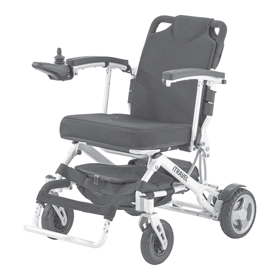
Page 7: Overview
OVERVIEW Model: iTravel The overview shows the most important com- ponents and operating devices of the electron- ic travelling wheelchair. Pos. Description (I) Back support (II) Arm support (III) Seat pad (IV) Utensils bag (V) Footplate (VI) Calf strap (VII) Steering wheel (VIII) Operating module (IX) Driving wheel (X) Drive... -
Page 8: Operating Module
OVERVIEW Operating module The overview shows the operating controls of the operating module. Pos. Description (I) Operating module (II) Battery charging socket (III) Joystick (IV) Reducing the adjusted speed preselection (V) Horn Í (VI) Control display of the battery capacity and fault indicator (VII) Switching the operating module on/off (VIII) Control display of the adjusted preselected... -
Page 9: Handling Of The Electronic Travelling Wheelchair
HANDLING OF THE ELEC- Decelerating the electronic travelling wheelchair TRONIC TRAVELLING For allotted braking of the electronic travelling WHEELCHAIR wheelchair slowly guide the joystick (steering and driving lever) back to the centre position Securing the electronic travelling (zero-setting). wheelchair ☞ The electronic travelling wheelchair stops The electronic travelling wheelchair is to be se- in shortest distance after releasing the joy- cured as follows to prevent it from rolling off... -
Page 10: Releasing The Brakes
Releasing the brakes Selecting the motor mode Only transfer into or out of the electronic Activate the brakes [1 on page 39]. travelling wheelchair when the electronic ☞ Therefore observe chapter Locking the travelling wheelchair is switched off and the brakes on page 9. -
Page 11: Battery Gauge
Battery gauge Preselect the maximum speed The battery gauge (5 on page 39) displays By pressing the keys (6 on page 39) and (7 on the existing battery voltage as follows: page 39) the preselectable final speed can be decreased or increased. The colours mean: The display (8 on page 39) shows the select- Green... -
Page 12: Joystick
Joystick Only move the joystick when the battery in- Forward motion dicator (5 on page 39) shows a constant light. Drive and steering movement Right curve The electronic travelling wheelchair is accel- erated and braked with the joystick (12 on page 39). -
Page 13: Keys And Symbols
Keys and symbols ON / OFF Switches the operating module on or off when pressing the key. ☞ The electronic will conduct a system test when switched on. ☞ Do not motion the joystick during this time. Horn A signal sounds for as long as the key is pressed. Max. -
Page 14: Selecting The Operation
SELECTING THE OPERATION PRE-OPERATION CHECKS In order to obtain operational readiness of the Before starting to drive, the following should electronic travelling wheelchair the following be checked: directions are to be carried out in the indicated The technical condition of the electronic order. -
Page 15: Battery Charging Procedure
Battery charging procedure ☞ Charge preferably during the night. A com- plete charge of the battery requires about Do not insert any objects other than the bat- 8 hours. tery charger plug into the battery charging ☞ When using the optionally available addi- socket. -
Page 16: Calf Belt
CALF BELT BACK SUPPORT BELT Do not drive without the calf belt. – Danger Fitting the back belt of accidents. The overlapping of the Velcro fastener has to The removable calf belt (17 on page 40) pre- be at least 10 cm! vents the feet from sliding off the back of the The tension of the back support is adjustable. -
Page 17: Seat Pad
SEAT PAD FOLDING/UNFOLDING Do not grab into the cross sections for fold- The seat cushion is attached to the seat belt ing/unfolding. – Danger of jamming! with velcro fasteners [27 on page 41]. For storage or transport e. g. in a motor vehicle UTENSILS BAG the electronic travelling wheelchair can folded easily [33 on page 41]. -
Page 18: Unfolding
Unfolding Wheelchair transport with lithium ion batteries If applicable open the folding fixation. Protect lithium ion batteries from tempera- 2. Pull the folded electronic travelling wheel- tures outside of the approved temperature chair backwards while lifting and in this range for transport as well as storage. way raise it up again [36 on page 42]. -
Page 19: Transport Of Lithium Ion Batteries
Transport of lithium ion batteries Use only the included lithium charge to Protect the lithium ion batteries so that nei- charge the lithium ion batteries. ther moisture nor foreign objects (e.g. small The guarantee is only preserved to its full ex- metal parts, nails or other conductive mate- tent when the included battery charger, sup- rials) can get into the gaps of the lithium ion... -
Page 20: Walking Aid Holder
< Information center > on our information are available in the < Informa- website < www.meyra.com > tion center > on our website < www.meyra. com >. Ramps and lifting platforms Observe the operating manual for the ramp... -
Page 21: Maintenance
MAINTENANCE An incorrect or neglected cleaning and main- tenance of the electronic travelling wheelchair results in a limitation of the product liability. Maintenance The following maintenance Instruction gives you a guide for carrying out the maintenance work. ☞ This maintenance schedule does not give information about the actual extent of work required on the electronic travelling wheelchair. -
Page 22: Tyres
Maintenance schedule WHEN WHAT REMARK Every 6 months Check View chapter Cleaning (depending on fre- page 28. – Cleanness. quency of use) Do it yourself or with the aid of a – General condition. helper. Every 6 -8 months Wheel attachments Do it yourself or with the aid of a (depending on dis- helper. -
Page 23: Fault Correction
Fault correction Fault Cause Remedy Battery indicator on the op- Operating module defective Have it repaired by the spe- erating module does not cialist workshop light up after the switch-on. Plug connection of the pow- Check the plug connections. er supply without contact. Batteries deep discharged. -
Page 24: Error Diagnostics
ERROR DIAGNOSTICS For fault correction on principle proceed as fol- lows: Errors, resp. information are shown through the Switch off the operating module. battery gauge, the display of the maximum fi- 2. Conduct the actions in column Remedy. nal speed and the display of adjustment func- tions. - Page 25 Fault Cause Remedy 7 blink impulses A system or joystick error. Do not touch the joystick during the initiation phase. – Switch the electronic travelling wheelchair off and on again. 8 blink impulses The operating module or the elec- Check cables and connecting tronic is defective or a system error plugs.
-
Page 26: Basic Safety Information
– Danger of accidents! This safety information is an extract of the Safety and general handling instructions, that Accompanying person can be found on our website: < www.meyra. The accompanying person must be made com >. aware of all possible danger situation before Do not put your fingers into open frame the start of his/her supportive involvement. -
Page 27: Crossing Obstacles
Never lean towards the downhill direction ing person must compensate for this drift by a when driving on rising, falling or transverse counter-steering. gradients. Crossing obstacles Avoid jerky changes of the driving condition (especially with critically adjusted driving pa- The ability to overcome obstacles is upon rameters as for example high delay values). -
Page 28: Electrical System
Electrical system the parking space, so that the wheelchair cannot slide away in case of an accident or An incorrect and/or inappropriate modifica- sudden braking manoeuvre. tion of the driving behaviour can impair the safety of the electronic travelling wheelchair Driving on public highways and the electronic travelling wheelchair user. -
Page 29: Finish
Further information to cleaning can be found ☞ In doing so the manufacturers instructions in the < Information center > on our website: are to be observed. < www.meyra.com >. Repairs Finish Repairs are generally to be carried out by a specialist dealer. -
Page 30: Spare Parts
DISPOSAL Spare parts Safety relevant parts or assembly groups are only to be assembled in a specialist work- shop. – Danger of accidents! Spare parts can only be ordered from special- ist dealers. In case of repair work, only original spare parts are to be used! ☞... -
Page 31: Information For The Specialist Dealer
Information for the specialist dealer talk with the doctor or therapist can be very helpful. A maintenance and service manual is available ☞ Any change to the manufacturer set pro- upon demand, in which you can for example gramming may result in an increased dan- find the following information: ger of accidents. -
Page 32: Tyre Pressure Of Pneumatic Tyres
Tyre pressure of pneumatic tyres – frequent driving upwards on ramps, – insufficient charging condition of the drive Maximum tyre pressure is printed on the tyres batteries, on each side. – low ambient temperature, Full tyre pressure – steering wheel –... -
Page 33: Values Acc. To Iso 7176-15 For Model 1.054
Values acc. to ISO 7176-15 for mod- Further technical data for model el 1.054 1.054 min. max. min. max. Sound level 62 dB(A) Overall length 970 mm 970 mm Protection class IP 51 Overall width 560 mm 650 mm Turning area 1030 mm –... -
Page 34: Meaning Of The Symbols On The Washing Instruction
Meaning of the labels on the elec- Further technical data for model tronic travelling wheelchair 1.054 Attention! min. max. Read the operating Amount of energy 269 Wh manuals and other provided documen- Max. battery dimen- 143 x 132 x 78 mm tation. -
Page 35: Meaning Of The Symbols On The Type Plate
WARRANTY / GUARANTEE Meaning of the symbols on the type plate Failure to observe the instructions in the operating manual, improperly carried out Manufacturer maintenance work and, especially, technical changes and additions (add-ons) carried out without our prior consent will lead to a gen- Order number eral loss of guarantee and product liability. - Page 36 For evaluation of our products you can use our < Information center > sector < PMS > on our website < www.meyra.com >. We reserve the right to make technical im- provements.
-
Page 37: Inspection Certificate
INSPECTION CERTIFICATE Recommended safety inspection 1st year (at least every 12 months) Vehicle data: Stamp of specialist dealer: Model: Signature: Delivery note no.: Place, date: Serial-no.(SN): Next safety inspection in 12 months Date: Recommended safety inspection 3rd year Recommended safety inspection 2nd year (at least every 12 months) (at least every 12 months) Stamp of specialist dealer:... -
Page 38: Warrantee / Guarantee Section
Warrantee / Guarantee section Please fill out! Copy if necessary and send the copy to the specialist dealer. Warranty / Guarantee Model designation: Delivery note no.: SN (view type plate): Date of delivery: Stamp of the specialist dealer: Inspection certificate for transfer Vehicle data: Serial-no.(SN): Stamp of specialist dealer:... - Page 44 Your specialist dealer MEYRA GmbH Meyra-Ring 2 32689 Kalletal Kalldorf GERMANY +49 5733 922 - 311 +49 5733 922 - 9311 info@meyra.de www.meyra.de MEYRA 205 347 001 (Status: 2021-11) All technical modifications reserved. Original operating manual.