Oki Microline 3390 User Manual
Ibm-/epson-compatible
Hide thumbs
Also See for Microline 3390:
- Setup & operating instruction (46 pages) ,
- User manual (156 pages) ,
- User manual (9 pages)
Table of Contents
Advertisement
Advertisement
Chapters
Table of Contents
Troubleshooting

Related Manuals for Oki Microline 3390


Summary of Contents for Oki Microline 3390
- Page 1 People to People Technology MICROLINE 3390/3391 IBM-/EPSON-compatible User Manual...
- Page 2 Accessories Bottom Tractor (narrow, wide version), Roll Paper Stand (narrow version only) Tractor feet Cut Sheet Feeder, CSF (1-Bin, 2-Bin; narrow, wide version) Serial Interfaces Cards: RS-232C, RS-232C / Current Loop, Pull Tractor (narrow, wide version) RS-422A...
-
Page 4: Legal Note
Legal note The information contained in this manual is as complete, accurate and up-to-date as possible. Provided legally permissible, we shall accept no liability for consequential damage in connection with the use of this manual. Otherwise, we shall only be liable for intent or gross negligence. -
Page 5: Guidance Through The Manual
Guidance through the manual The first part of this manual is directed largely at users who have no or very little technical knowledge. Experienced users, suppliers and technicians will find additional technical information in the "Programming" part and in the appendices. There are three ways of accessing the information in this manual: You can read the text in the order in which the manual is arranged. -
Page 6: Table Of Contents
Chapter 1: Assembling and setting up the printer Chapter 2: A guided tour of the printer Chapter 3: Paper handling Chapter 4: Printer menu settings Chapter 5: Printer control Chapter 6: Consumables and cleaning Chapter 7: Accessories Chapter 8: Troubleshooting Chapter 9: Packing the printer for transportation Chapter 10: IBM - Standard functions Chapter 11: IBM - Graphics... - Page 8 Appendix A: Technical Data Appendix B: Code pages Appendix C: Bar codes Appendix D: Interface data Appendix E: Paper formats and printing areas Appendix F: Index / Glossary Appendix G: Trademarks Appendix H: Short reference...
- Page 9 Table of contents Legal note Guidance through the manual Safety advice Servicing / maintenance XVII Advice and warning symbols XVIII Meaning of text styles in the manual XVIII Consumables / accessories Machine-readable fonts Further information Chapter 1: Assembling and setting up Unpacking the printer Checking the items supplied Assembling the printer...
-
Page 10: Chapter 3: Paper Handling
Button functions in ON LINE / OFF LINE mode Button functions in menu mode Print functions PRINT QUALITY CHARACTER PITCH RESET Chapter 3: Paper handling Notes on paper types Paper lever Adjusting for the paper thickness Print head lever Adjusting the print head gap Paper feed: cut sheets Paper feed: continuous paper Feeding continuous paper from the rear... -
Page 11: Chapter 6: Consumables And Cleaning
Chapter 5: Printer Control Emulation Printer drivers Characters and control characters Printing under DOS Printing under DOS with serial interface Troubleshooting Chapter 6: Consumables and cleaning Changing the ribbon cassette Inserting a new ribbon cassette Cleaning Chapter 7: Accessories Cut sheet feeder Checking the items supplied Adjusting the length of the feed rail Installing the feed rail... -
Page 12: Chapter 9: Packing The Printer For Transportation
7-25 The roll paper stand 7-25 Checking the items supplied 7-25 Installation 7-26 Paper feed 7-28 Interface cards 7-28 Installation Chapter 8: Troubleshooting Possible faults Fault tables Major faults Testing options Chapter 9: Packing the printer for transportation Chapter 10: IBM - Standard Functions 10-1 Print quality 10-3... -
Page 13: Chapter 13: Ibm - Characters Sets
Chapter 13: IBM - Character Sets 13-1 IBM Character Sets 13-1 National Character Sets 13-2 Code Pages Chapter 14: Epson - Standard Functions 14-1 Print quality 14-2 Print modes 14-6 Print attributes 14-8 Multifunction commands 14-9 Tabulators 14-12 Positioning 14-15 Page formatting 14-17 Line spacing... -
Page 14: Chapter 17: Epson - Characters Sets
Chapter 17: Epson - Character Sets 17-1 Epson Character Sets 17-1 National Character Sets 17-2 Code Pages Appendix A: Technical Data Appendix B: Code Pages Overview Conversion table Code pages Appendix C: Bar Codes Bar code types Positioning Selection of type and size of Bar code Printing of a 24 pin Bar code C-17 Examples... - Page 15 D-22 Coresident RS-232C/Current Loop Interface D-22 Technical Data D-23 Pin description D-24 Interface selection D-26 Transmission protocols D-29 Connections of the Current Loop Interface D-30 Diagrams D-37 Interface test Appendix E: Paper formats and print areas Continuous paper Format Weight Thickness Perforation Further information...
-
Page 16: Safety Advice
Safety advice Your printer has been developed with the utmost care to ensure safe, reliable operation over many years. Like all electrical devices, there are a few basic precautions you need to observe. These pre- cautions are necessary in the first instance for your own safety but also protect the printer against any damage. -
Page 17: Servicing / Maintenance
Power supply Ensure yourself ... that the ratings of the power supply match the ratings shown on the back of the printer. If in doubt, ask your supplier; that the printer is connected to an earthed mains socket with the cable supplied;... -
Page 18: Advice And Warning Symbols
Advice and warning symbols Observe all warnings and instructions stated on the product itself and in the accompanying documentation. At particularly impor- tant points in the manual, warnings are marked with appropriate symbols. NOTE: text passages marked thus contain supplementary informa- tion or instructions. -
Page 19: Meaning Of Text Styles In The Manual
Meaning of text styles in the manual To emphasise important passages in the text or differentiate between the meaning of a printer function and a printer message, the following text styles or emphases are used in the manual: BOLD BLOCK CAPITALS represent the display lamps of the control panel. -
Page 20: Machine-Readable Fonts
Machine-readable fonts The perfect readability of fonts such as OCR-A, OCR-B or bar codes (EAN, UPC, Zip) by machines is affected by ... the printing technique (resolution, edge sharpness); the technical state of the printer; the quality of the printing medium (toner, ink ribbon); the state of the print material (glossiness, smoothness, coating, age, reflection, surface uniformity);... -
Page 21: Chapter 1: Assembling And Setting Up
Chapter 1: Assembling and setting up Chapter 1: Assembling and setting Unpacking the printer The printer is supplied in separate parts in a cardboard box. 1. Take the printer and components out of the box. 2. Remove the packing material. Keep the original packing so that you can transport the printer safely should the need arise later Checking the items Check that the individual items supplied are complete and un-... -
Page 22: Assembling The Printer
Chapter 1: Assembling and setting up Assembling the printer Location Make sure ... • the printer is standing on a stable, flat surface. To prevent overheating, make sure there is free space all around the printer; openings should not be covered. Never place the printer directly next to a radiator or the air outlet of an air- conditioning system. -
Page 23: Setting Up The Printer
Chapter 1: Assembling and setting up • all reasonable precautions have been taken to prevent damage to the power cable. Do not place objects on the cable and make sure it is routed so that nobody walks on it or trips over it; •... -
Page 24: Inserting The Ribbon Cassette
Chapter 1: Assembling and setting up Inserting the ribbon cassette Original ribbon cassettes are specially developed for your print- er. Among other things, this concerns the ink, which contains lubricants, and the fabric of the ribbon. Warning! The use of non-original ribbons can result in damage to the print head. -
Page 25: The Paper Support
Chapter 1: Assembling and setting up 4. Tilt the cassette carefully down over the print head until you feel it click into place. 5. Turn the blue transport knob of the cassette in the direc- tion of the arrow to tension the ribbon. -
Page 26: Raising The Paper Support
Chapter 1: Assembling and setting up Raising the paper 1. Slightly raise the paper support at the back. support 2. Pull the support forwards and slide it at this angle to its end position. 3. Align the guide rails so that they just touch the edges of the paper. -
Page 27: Removing The Paper Support
Chapter 1: Assembling and setting up The paper support must be removed to fit accessories such as the Removing the paper cut sheet feeder or roll paper stand. support 1. Move the paper support into the horizontal home posi- tion. 2. -
Page 28: Removing The Paper Separator
Chapter 1: Assembling and setting up Caution! The print head may be hot and can burn your hands. Wait until the print head has cooled down. Removing the paper Remove the paper separator by holding it on both sides separator and pulling it gently to- wards the front of the print- er. -
Page 29: Connecting The Printer To The Computer
Chapter 1: Assembling and setting up Connecting the printer to the computer It is important to read the safety instructions on the first pages of this manual. Before you can use the printer, you have to connect it to your computer and to the power supply. Your printer is supplied with a parallel Centronics interface as standard. -
Page 30: Connecting The Printer To The Power Supply
Chapter 1: Assembling and setting up 1. Plug the printer end of Fitting interface cable parallel interface cable into the socket on the back of the printer. Secure cable means of the two clips. 2. Connect the other end of the interface cable to the corresponding socket of your computer. -
Page 31: Emulation / Printer Drivers
Chapter 1: Assembling and setting up 2. Plug the other end of the cable into an earthed mains outlet sock- 3. Switch on the printer and the computer by means of the respec- tive power switches. Your printer is now ready for operation. Emulation / printer drivers In the chapter "Printer drivers"... -
Page 32: Chapter 2: A Guided Tour Of The Printer
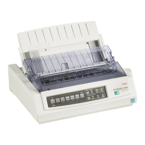
Chapter 2: A guided tour of the printer Chapter 2: A guided tour of the printer The printer and its components Front view paper support printer cover operator panel platen knob The operator panel indicators inform you of the operating status of the printer. -
Page 33: Inside View
Chapter 2: A guided tour of the printer Inside view platen print head and paper seperator ribbon cassette The print head is the part of the printer that contains the printing pins. The original ribbon cassette contains the high-quality ink necessary for perfect printing. -
Page 34: Rear View
Chapter 2: A guided tour of the printer Rear view Centronics-interface paper lever power switch socket panel power socket The printer and computer are connected by means of the interface socket. The parallel Centronics interface or a serial interface (ac- cessory) are provided for this purpose. -
Page 35: The Operator Panel
Chapter 2: A guided tour of the printer The operator panel The operator panel allows you to control the printer and change settings. The indicator lamps show the current status of the printer. The meaning and function of the buttons depends on the current operating mode of the printer. -
Page 36: The Buttons
Chapter 2: A guided tour of the printer The buttons Micro Feed Down: The paper is transported backwards in steps of 1/180 inch (downwards). Simultaneously press the SHIFT and Down buttons to be able to use the »Micro Feed Down« function. Micro Feed Up: The paper is transported forwards in steps of 1/180 inch (upwards). - Page 37 Chapter 2: A guided tour of the printer LF: Pressing this button (Line Feed) causes the printer to feed the paper forwards by one line. If a cut sheet feeder is fitted (accessory) and there is no paper in contact with the platen, pressing this but- ton will cause a new sheet of paper to be fed from the current paper tray to the first printable line on the paper.
-
Page 38: Print Functions
Chapter 2: A guided tour of the printer In this mode, you can adjust the printer to your individual require- Button functions in ments. The functions you select are automatically activated when menu mode you switch on the printer. The alterations you make in the printer menu are stored in the printer and consequently become standard settings. - Page 39 Chapter 2: A guided tour of the printer The PRINT QUALITY button enables you to determine the print PRINT QUALITY quality and the font you require for the document to be printed. An indicator lamp shows the currently activated font and print quality. Further information on printing speed and print quality is to be found in...
- Page 40 Chapter 2: A guided tour of the printer To reset the printer to the settings selected in the menu, switch the RESET printer OFF LINE and simultaneously press the buttons SHIFT and RESET. The printer switches to ready to print status (ON LINE).
-
Page 41: Notes On Paper Types
Chapter 3: Paper handling Chapter 3: Paper handling This chapter explains the different ways the printer handles paper (feeding, setting of printing position, changing between different types of paper). Notes on paper types • Always use good quality standard paper! Please also read the notes in Appendices A and E. -
Page 42: Paper Lever
Chapter 3: Paper handling Paper lever Move the paper lever on the right side of the printer to the position that is appropriate to the feed path for the paper. Continuous paper feed- ing: for continuous pa- per which is fed via the bottom or pull tractor feed, the lever must be in the BOT (bottom) po-... - Page 43 Chapter 3: Paper handling Paper thickness Lever position 0.08 mm 0.15 mm 0.22 mm 0.29 mm 0.36 mm Adjusting the print Should you wish to print on thick types of paper, the gap between print head and platen must be increased: head gap Caution! The print head moves and can cause injury to the hands.
- Page 44 Chapter 3: Paper handling 3. Release the locking plate of Locking plate the print head by moving the plate upwards and side- ways. 4. Remove the locking plate and place it to one side. 5. Remove the print head from its slot.
- Page 45 Chapter 3: Paper handling 7. Insert the plate in front of the print head holder, making sure that the plate fits even- Print head holder 8. Replace the print head in the slot of the print head car- riage. 9. Place the locking plate onto the print head holder, mak- ing sure that the pin on the left of the holder properly...
- Page 46 Chapter 3: Paper handling 10. Pivot the locking plate down thus securing the print head. 11. Replace the ribbon cassette. 12. Close the cover of the printer and switch on the printer. By repositioning the distance plate, the gap between the print head and the platen is increased.
-
Page 47: Paper Feed: Cut Sheets
Chapter 3: Paper handling Paper feed: cut sheets The paper support ensures precise automatic feeding of cut sheets. 1. Move the paper lever on the right of the printer to the TOP position (cut sheet). 2. Switch the printer on. 3. -
Page 48: Paper Feed: Continuous Paper
Chapter 3: Paper handling 4. Insert a sheet of paper into the paper support and adjust the rails of the paper guide so that they just touch the edges of the paper. Start by aligning the left edge of the paper to the mark provided. - Page 49 Chapter 3: Paper handling 2. Press downwards on the back of the paper support. This will release it from its catch. Remove it from the printer and place it to one side. Warning! Direct pressure on the platen can cause damage to the print head and pins.
- Page 50 Chapter 3: Paper handling 4. Open the top part of the cov- 5. Place the continuous paper onto the first sprocket pins and close the cover again. 6. Adjust the right sprocket drive to suit the width of paper as de- scribed above.
- Page 51 Chapter 3: Paper handling 9. Set the top of form if necessary with the »Top Of Form« function. This is described later in the manual. Feeding continuous If the tractor feed is installed, you can also feed continuous paper from the bottom. This option is available if you have a printer stand paper from the or table with a slot which allows continuous paper to be fed in from bottom (tractor feed,...
- Page 52 Chapter 3: Paper handling If continuous paper is being fed from the rear and you wish to Changing from change to cut sheets, proceed as follows: continuous paper to cut sheets 1. Part the already printed pages along the perforation. 2.
-
Page 53: Changing Top Of Form
Chapter 3: Paper handling Setting the top of page (Top Of Form) With the »Top Of Form« function, you can set the line where print- ing is to start, the so-called top of form. A clear paper guard is fitted at the front on the print head car- riage. - Page 54 Chapter 3: Paper handling Note! To set the top of form to the standard setting, simultaneously press the SHIFT and TOF buttons. There must be no paper in the print path when doing this. 5. The top of form can be set differently for each type of paper feed, irrespective of whether you are feeding cut sheets manually, us- ing the cut sheet feeder (CSF) or using continuous paper.
-
Page 55: Automatic Advance To Form Tear-Off Position
Chapter 3: Paper handling Automatic advance to Form Tear-Off position If this function is active, printed pages of continuous paper are transported from the TOF position to the Form Tear-Off position to allow you to tear them off there. To do this, the continuous paper must be fed from the rear or via the additional bottom tractor feed (accessory) from below. - Page 56 Chapter 3: Paper handling With the »Form Tear-Off« function activated, you can check and set Checking the top of the top of form by pressing the TEAR button in OFF LINE mode; form the paper is drawn back to the top of form. Reset the top of form by pressing the Micro Feed Up/Down buttons with the SHIFT button pressed.
-
Page 57: The Printer Menu
Chapter 4: Printer menu settings Chapter 4: Printer menu settings The printer menu The printer menu is used to adjust your printer to suit the applica- tion. Thus, you can use the printer menu to choose the emulation. You can adjust the page length for continuous paper or cut sheets, change the font and make other settings. - Page 58 Chapter 4: Printer menu settings • On pressing the GROUP button, the next group and the first Changing the menu menu item associated with it are output. If you simultaneously settings press the SHIFT button, the preceding menu group is selected. •...
- Page 59 Chapter 4: Printer menu settings 4. You can select a value for Pitch. Since the first value is 10 cpi, you need to press the SET button three times until the value 17.1 cpi appears. End menu mode Hold down the SHIFT button and press the EXIT button. The val- ues last selected now become effective and the printer returns to print mode.
- Page 60 Chapter 4: Printer menu settings GROUP ITEM The factory defaults for menu Printer Control Emulation Mode EPSON LQ, IBM PPR, IBM AGM items are printed in bold. The font LQ Orator can only Font Print Mode LQ Courier, LQ Roman, LQ Swiss, LQ Swiss Bold, be selected via the menu and LQ Orator, LQ Gothic,...
- Page 61 Chapter 4: Printer menu settings GROUP ITEM Rear Feed Line Spacing 6 LPI, 8 LPI Form Tear-Off Off, 500 ms, 1 sec, 2 sec Skip Over Perforation No, Yes The menu item Page Width Page Width 13.6 ", 8 " appears only for wide printer models.
- Page 62 Chapter 4: Printer menu settings GROUP ITEM Set-Up Graphics Uni-directional, Bi-directional Receive Buffer 8 K, 23 K, 1 Line Paper Out Override No, Yes Print Registration 0, 0.05mm, 0.10mm, 0.15mm, 0.20mm, 0.25mm Left, 0.25mm Right, 0.20mm, 0.15mm, 0.10mm, 0.05mm Operator Panel Function Full Operation, Limited Operation Reset Inhibit...
- Page 63 Chapter 4: Printer menu settings GROUP ITEM Parallel I/F I-Prime Buffer Print, Buffer Clear, Invalid Pin 18 +5 V, Open Auto Feed XT appears only Auto Feed XT Invalid, Valid when Epson emulation is selected. The menu items of the group Serial I/F only appear when a serial interface is installed.
- Page 64 Chapter 4: Printer menu settings The menu items of group CSF Bin 1 listed below appear only when a cut sheet feeder is installed. The menu items of the group CSF Bin 2 accordingly appear only when a cut sheet feeder is installed with two trays.
-
Page 65: Explanation Of Menu Items
Chapter 4: Printer menu settings Explanation of menu items Printer Control Emulation Mode: You use this item to define the command set. The emulations available to you are Epson LQ, IBM ProPrinter and IBM AGM. The Alternative Graphics Mode (AGM) includes partial compatibility with the Epson LQ series which is largely limited to graphics and line feed commands. - Page 66 Chapter 4: Printer menu settings Line Spacing: Select between 6 lpi (lines per inch, corresponds to Rear Feed, 1/6 inch line spacing) or 8 lpi (corresponds to 1/8 inch line spac- Bottom Feed ing). Form Tear-Off: If this function is activated, continuous paper is automatically transported to the tear-off position after the time pre- set in the menu (500 ms, 1 sec, 2 sec).
- Page 67 Chapter 4: Printer menu settings Page Length Control: Where cut sheets are being fed from above (Top Feed), the page length can be set via the menu or program commands (by Menu Setting). If, however, you set the value by Actual Page Length, the page length is automatically detected by means of the end of page sensor.
- Page 68 Chapter 4: Printer menu settings Operator Panel Functions: Normally, all the buttons of the opera- tor panel are active, but if you choose Limited Operation, the but- tons PRINT QUALITY, CHARACTER PITCH and menu mode are blocked. The corresponding functions can then only be controlled by the software.
- Page 69 Chapter 4: Printer menu settings Auto Select: If a sheet of paper has been fed automatically from the paper support when the setting is No, the printer stays in the OFF LINE status. If Yes is selected, the printer switches to ON LINE when a sheet of paper is fed and the SEL lamp lights.
- Page 70 Chapter 4: Printer menu settings CSF Type: The menu item CSF Type only appears for wide printer models. If you are working with a wide cut sheet feeder, the value must be set to Wide. If you are using a narrow cut sheet feeder with a wide printer, set the value to Narrow.
- Page 71 Chapter 4: Printer menu settings Diagnostic Test: Activates a diagnostic test of the interface. For fur- ther information, please refer to Appendix D. Busy Line: Defines the line to be used for the busy signal. Baud Rate: Defines the speed of data transmission. DSR Signal: Activates or deactivates the DSR signal (data set ready).
-
Page 72: Printer Drivers
Chapter 5: Printer Control Chapter 5: Printer Control Emulation An emulation is a »copy« of the functions of a specified device. That means your printer is capable in a certain emulation of executing the commands and functions of this particular device. In addition, extra functions are in most cases provided that go beyond the perform- ance specification of the emulated device. - Page 73 The lower the printer driver appears in the list, the fewer the functions supported. Epson-Emulation IBM-Emulation OKI ML 3390/3391 OKI ML 3390/3391 OKI ML 590/591 Elite OKI ML 590/591 Elite OKI ML 590/591 OKI ML 590/591 OKI ML 390/391 Elite OKI ML 390/391 Elite...
- Page 74 Chapter 5: Printer Control Characters and control characters The print data is transmitted by character. Every character is repre- sented by 8 bits and thus expresses a certain position within the character set currently selected. Most character sets are based on ASCII code (American Standard Code for Information Interchange).
- Page 75 Chapter 5: Printer Control It is possible to print an ASCII or print file by using the TYPE com- TYPE mand and diverting the output to the LPT1 device. Example: TYPE C:\AUTOEXEC.BAT > LPT1: TYPE C:\TEXTS\LETTER.TXT > LPT1: In the first instance, the file AUTOEXEC.BAT is printed from the root directory and in the second case the file LETTER.TXT is printed from the TEXTS subdirectory.
- Page 76 Chapter 5: Printer Control Entering the control character CTRL-P once again switches off print- ing of the screen data on the printer. Printing under DOS with a serial interface (RS-232C) When printing under DOS, make sure only the transmission proto- col Ready/Busy (hardware handshake) is supported.
-
Page 77: Troubleshooting
Chapter 5: Printer Control • The serial interface settings in the computer are defined with the MODE command as follows: MODE COM1: 9600,n,8,1,p Please refer to the DOS manual for more information on the MODE command. • Notes and further information on the serial interface (wiring, pin assignment, etc.) are to be found in the Interface Data appendix. - Page 78 Chapter 6: Consumables and cleaning Chapter 6: Consumables and cleaning Changing the ribbon cassette If the contrast of the printed characters is deteriorating, the ribbon needs to be changed. To do this, proceed as follows: Caution! The print head moves and can cause injury to the hands. Switch the printer OFF LINE and wait until the print head stops moving.
- Page 79 Chapter 6: Consumables and cleaning 4. Hold the used ribbon cas- sette at the top and carefully lift it over the print head. Lift cassette over the print head Inserting a new The original ribbon cassettes of the manufacturer´s are specially de- veloped for your printer.
- Page 80 Chapter 6: Consumables and cleaning 3. Tilt the cassette carefully down over the print head until you feel it click into place. 4. Turn the blue transport knob of the cassette in the direc- tion of the arrow to tension the ribbon.
- Page 81 Chapter 6: Consumables and cleaning • Remove paper dust only with a soft brush such as a paint brush. • Do not grease or oil any parts within the printer, this can cause damage. • Do not use any solvents or aggressive cleaning agents on the case or in the machine, this can cause damage.
-
Page 82: Cut Sheet Feeder
Chapter 7: Accessories Chapter 7: Accessories The accessories described in this chapter extend the range of func- tions provided by your printer. For your safety, and to avoid dam- age to the machine: • ... switch the printer off before installing accessories, •... - Page 83 Chapter 7: Accessories Check that the individual items Checking the items supplied are complete and un- supplied damaged. You should have re- ceived: • 1 feed rail • 1 front paper stand • 1 to 4 rear paper stands Remove the packing material. Keep the original packing material safe so that you can transport the sheet feeder safely at a later date if necessary.
- Page 84 Chapter 7: Accessories 3. Align the holes of the exten- sion precisely to the holes of the rail. 4. Fasten screws once again. Extended in this way, the paper feed rail will now fit the wide printer. If, on the other hand, you are using the narrow print- er, the rail must not be extend- Installing the...
- Page 85 Chapter 7: Accessories 1. Switch the printer off and open the printer cover. 2. Remove the paper support (see also Chapter 1). 3. Remove the ribbed paper separator by first pulling it forwards and then removing it from its catch arrangement (see also Chapter 1).
- Page 86 Chapter 7: Accessories 1. Install the cut sheet feeder Installing the cut with its mounting brackets sheet feeder onto both ends of the platen shaft so that it is firmly seated. 2. Turn the platen knob so that the gearwheel on the left end of the sheet feeder engages with the gearwheel of the platen.
- Page 87 Chapter 7: Accessories 5. Fit the rear paper stand or stands as the case may be onto the rail of the paper guide. 6. Now insert the front paper stand. 7. To ensure that the machine feeds and handles the paper perfectly, the paper lever at the right end of the printer must point to the cut sheet...
- Page 88 Chapter 7: Accessories The paper tray of the cut sheet feeder has a maximum capacity of Paper feed 100 sheets (90 g/m ) or 170 sheets (60 g/m ) of standard paper. A mark on the left guide rail indicates the maximum amount of paper.
- Page 89 Chapter 7: Accessories 4. Adjust the right paper guide so that the right side of the guide is flush with the right edge of the sheet of paper. Do not force the uprights to- gether. The guide rail can be released and locked again by moving the locking lever to appropriate...
- Page 90 Chapter 7: Accessories Cut sheets can also be fed into the printer when the cut sheet feeder Manual paper feed is installed. It is essential, however, that there is no paper in the normal paper path of the printer. There are two possible modes for manual feeding: Feeding cut sheets If the printer is ON LINE while...
- Page 91 Chapter 7: Accessories If you are using single-part continuous paper, you can leave the cut Feeding cut sheets sheet feeder on the printer and alternately feed and process contin- and continuous uous paper and cut sheets from the sheet feeder. To do this, trans- paper port the continuous paper into the PARK position as described in Chapter 3.
- Page 92 Chapter 7: Accessories Should you wish to fit a narrow cut sheet feeder onto a wide print- Adjusting the moun- er, you will have to fit the mounting bracket for the wide roller as ting bracket described below. You will need a cross-head screwdriver for this purpose.
- Page 93 Chapter 7: Accessories 6. Move the right bracket rail approximately 15 cm to the right; the mounting bracket is now extended to approxi- mately 45 cm wide. Align the fixing hole precisely to the pin and the threaded hole on the cut sheet feeder and refit the right hand screw (B).
- Page 94 Chapter 7: Accessories To install the tractor feed, proceed as follows: Installation Caution! The print head moves and can cause injury to the hands. Switch the printer OFF LINE and wait until the print head stops moving. Caution! The print head may be hot and can burn your hands. Wait until the print head has cooled down.
- Page 95 Chapter 7: Accessories 3. Remove the paper support by pressing it downwards at the back. This will release it from its catch (see also Chapter 1). 4. Fit the tractor feed onto the printer. When doing this, fit the slots at each end of the tractor onto the pins of the holder printer...
- Page 96 Chapter 7: Accessories Note! Do not use the “Park” function in conjunction with the tractor feed otherwise the continuous paper will run completely out of the tractor guide. With the tractor feed fitted, you can feed continuous paper from Feeding continuous below the printer and print on it.
- Page 97 Chapter 7: Accessories 4. Release the locking lever for the left sprocket feed and move this to the required po- sition. Fasten the left roller again with the locking lever. Locking lever 5. Open the cover of the left sprocket feed, fit the contin- uous paper onto the first two sprocket pins.
- Page 98 Chapter 7: Accessories 7. Now position the right hand sprocket feed in the same way to suit the width of pa- per. Make sure that the pa- per is slightly tensioned. 8. Switch the printer on. The print head will move to the left end of the platen and the active indicators on the op- erator panel will light.
- Page 99 Chapter 7: Accessories The bottom tractor feed The bottom tractor feed gives you an additional means of feeding continuous paper from beneath the printer. For this purpose, the printer is raised up on the two feet supplied with the feeder. Checking the items Check that the individual items supplied are complete and un-...
- Page 100 Chapter 7: Accessories 1. Switch off the printer. 2. In order to fit the feet, set the printer on its left side with the platen knob pointing up- wards. The right support foot is to be fitted first. 3. Hook the corners of the sup- port foot into the cutouts provided for this in the bot- tom of the printer.
- Page 101 Chapter 7: Accessories 6. Once the two feet are fitted, you need to fold them out to allow you to install the trac- tor feed. As a result, the printer will tilt backwards. Replace the platen knob. Installing the tractor To install the tractor feed, you need firstly to fold out the two feed...
- Page 102 Chapter 7: Accessories 1. Place the tractor feed with the cutouts at both ends onto the retaining pins on the bot- tom of the printer (arrow). 2. Gently push the tractor feed towards the front of the printer. 3. The mounting hooks of the tractor must click audibly into place.
- Page 103 Chapter 7: Accessories 1. Move the paper lever on the Feeding continuous right of the printer back to paper the continuous paper posi- tion (REAR). The symbol on the cover for cut sheet han- dling (TOP) shows you the correct lever position. Warning! Direct pressure on the platen can cause damage to the print head and pins.
- Page 104 Chapter 7: Accessories 4. To adjust the left sprocket feed to suit the width of the paper, release the locking le- ver (pull forwards). Move the feed unit to the required position and lock it with the lever again. 5. Now adjust the right hand sprocket feed in the same way to suit the paper width.
- Page 105 Chapter 7: Accessories You can set the values for paper handling as you wish by means of the printer menu in the Bottom Feed group. Changing between If you are feeding continuous paper from the rear and wish to use continuous paper from the bottom tractor feed, proceed as follows: different formats of continuous paper...
- Page 106 Chapter 7: Accessories The roll paper stand The roll paper stand permits you to use telex roll paper or special paper for specific applications. Check that the individual items Checking the items supplied are complete and un- supplied damaged. You should have re- ceived, depending on the mo- del: •...
- Page 107 Chapter 7: Accessories 1. Replace the old support with the new paper support pro- vided with the roll paper stand. The paper support is installed as described in Chapter 1. 2. Place the hooks of the roll paper stand precisely in the cutouts of the paper support and tilt the support back- wards.
- Page 108 Chapter 7: Accessories 2. Slip the paper beneath the platen from the back with the edges of the paper lying against the platen. Now turn the platen knob to feed the paper around the platen. Warning! Direct pressure on the platen can cause damage to the print head and pins.
-
Page 109: Interface Cards
Chapter 7: Accessories Interface cards In addition to the built-in parallel interface, three other different serial interface cards are available: • RS-232C • RS-232C/Current Loop • RS-422A Installation This section explains how to install the interface card. Technical details on these interfaces such as pin assignment, configuration by means of the printer menu and... - Page 110 Chapter 7: Accessories 2. Remove the panel on the right, rear side of the printer by breaking it out with a slot-head screwdriver or by cutting it out with a knife. 3. Take the card out of its pack- A clip may be enclosed which is not required for this model.
- Page 111 Chapter 7: Accessories Note! Make sure that the parallel and serial interface cables are not installed or used at the same time as this can result in malfunction. 5. Connect the other end of the interface cable to the appropriate socket of your computer.
- Page 112 Chapter 8: Troubleshooting Chapter 8: Troubleshooting Most printing problems are easy to solve. Before calling customer service, check the possible causes of faults below. Small malfunc- tions are usually very easy and quick to remedy yourself. Possible faults This summary covers both the fault and possible remedies. Ascer- tain in which part of the machine the malfunction is located and read the advice described.
- Page 113 Chapter 8: Troubleshooting ...nothing is being printed although the computer is sending data? The printer may be switched OFF LINE. If the SEL lamp is not lit, press the SEL button. Check that the interface cable is correctly con- nected to your printer and computer..a paper jam occurs? Paper jams rarely occur even if continuous paper and cut sheets are being alternately processed.
- Page 114 Chapter 8: Troubleshooting ...individual dots of the print-out are missing? The print head may be damaged. Contact your supplier..the print-out appears faint? Replace the ribbon cassette with a new one as described in Chapter 6 and adjust the paper thickness correctly. If there is no marked improvement in the printing, contact your supplier.
- Page 115 Chapter 8: Troubleshooting Fault tables Malfunctions are indicated by the blinking of the ALARM lamp. The other lamps show the type of fault. Faults that can be The messages listed point to faults that can generally be remedied remedied by the by the user.
- Page 116 Chapter 8: Troubleshooting Description UTL PRES 10 cpi 12 cpi 20 cpi PROP • • The serial interface card is incorrect- ly installed. Remove the card and re- install it. • • The drive of the print head carriage (space motor) is jammed or faulty. Make sure that no foreign material is preventing the carriage from moving correctly (staple, paper dust, etc.).
- Page 117 Chapter 8: Troubleshooting Major faults The following fault messages are unlikely to be displayed in normal use. They are listed here for the sake of completeness. Should any of these faults occur, contact your supplier. The ALARM lamp also blinks when these faults occur; the follow- ing lamps light permanently in addition.
- Page 118 Chapter 8: Troubleshooting Testing options The printer is provided with a number of simple means for testing that it is functioning correctly. Use one of the available tests when you wish to check whether the printer is working properly. Details on the program version and emulation of your printer are contai- ned in the header above the following test print-outs.
- Page 119 Chapter 8: Troubleshooting This test will help you to check the current print quality and the Available fonts available fonts. The print-out of available fonts covers one page and ends automatically, but can also be cancelled prematurely by pres- sing the SEL button. •...
- Page 120 Chapter 9: Packing the printer for transportation Chapter 9: Packing the printer for transportation Should you need to send off or transport the printer (dispatch, change of location, repairs), follow the instructions below to ensure the secure packing of your machine. Printers not packed in accor- dance with these instructions could be damaged during transporta- tion.
- Page 121 Chapter 10: IBM - Standard Functions Chapter 10: IBM - Standard Functions This chapter contains the commands for controlling IBM ProPrinter X24/XL24 emulation printer functions. The individual commands are listed within the function groups such as print quality, page for- matting, etc.
- Page 122 Chapter 10: IBM - Standard Functions = integer value (Font-ID/256) = Font-ID - (m * 256) Following values for m and m are fixed: Typeface no change Courier Courier Courier Courier Courier Courier Courier Courier Courier Courier Prestige Elite Prestige Elite Prestige Elite Prestige Elite Prestige Elite...
-
Page 123: Print Modes
Chapter 10: IBM - Standard Functions Character pitch no change 20 cpi 17 cpi 15 cpi 12 cpi 10 cpi defines whether the proportional typeface is selected. In this case has the value 2. Is r = 1 a non proportional typeface, it is selected. Is r = 0 the last selected item (proportional or non proportional), it is kept. - Page 124 Chapter 10: IBM - Standard Functions The pitch can also be defined via the CHARACTER PITCH menu item or via the control panel. The spacing can also be defined via a multifunction command. Double width Function Dec. Hex. ASCII printing Start double width 27 87 49 1B 57 31...
- Page 125 Chapter 10: IBM - Standard Functions For certain applications the maximum number of characters in a line has to be indicated. This depends on the pitch selected. The following table shows the maximum number of characters per line. Pitch Characters per line Narrow printer Wide printer 5 cpi...
-
Page 126: Print Attributes
Chapter 10: IBM - Standard Functions Print attributes Emphasized / Function Dec. Hex. ASCII enhanced Start emphasized 27 69 1B 45 ESC E Stop emphasized 27 70 1B 46 ESC F Start enhanced 27 71 1B 47 ESC G Stop enhanced 27 72 1B 48 ESC H... - Page 127 Chapter 10: IBM - Standard Functions Superscript characters are printed above the base line and are used for exponents (x ) and other typographical effects. Subscript is par- ticularly suitable for chemical formulae (H O). Superscript and sub- script characters are represented in all pitches in half character height and normal character width.
- Page 128 Chapter 10: IBM - Standard Functions Print mode Pitch Font Data Processing Quality 12 cpi resident Letter Quality 12 cpi resident Data Processing Quality 12 cpi resident Letter Quality 12 cpi resident Data Processing Quality 17,1 cpi resident Letter Quality 17,1 cpi resident Data Processing Quality...
- Page 129 Chapter 10: IBM - Standard Functions With this command, in addition to the character height you can also define the character width and the line spacing. The different com- binations of these three functions result from the values for the var- iables n and n defines the character height and line spacing,...
- Page 130 Chapter 10: IBM - Standard Functions Tabulators Horizontal Function Dec. Hex. ASCII tabulators Skip to next horizontal Set horizontal tabs 27 68 n 1B 44 n ESC D n ... n ... n ... n n = 1 to 255 k = 1 to 28 Clear horizontal tabs 27 68 0...
- Page 131 Chapter 10: IBM - Standard Functions Max. tabulator position Pitch Narrow printer Wide printer 10 cpi 12 cpi 15 cpi 17.1 cpi 20 cpi Function Dec. Hex. ASCII Vertical tabulators Skip to next vertical Set vertical tabs 27 66 1B 42 ESC B ...
- Page 132 Chapter 10: IBM - Standard Functions Positioning Relative dot Function Dec. Hex. ASCII positioning Relative horiz. 27 100 1B 64 ESC d dot position to the right Relative horiz. 27 101 1B 65 ESC e dot position to the left With these commands you can indent a line, for example at the be- ginning of a paragraph, where the spacing is measured in relative dot columns.
-
Page 133: Page Formatting
Chapter 10: IBM - Standard Functions Function Dec. Hex. ASCII Indicate next print position Start indication 27 105 1 1B 69 01 ESC i SOH Stop indication 27 105 0 1B 69 00 ESC i NUL With this command you can switch on and off the mode which en- ables indication of the next print position. - Page 134 Chapter 10: IBM - Standard Functions Normally a standard length can be set in the Page Length menu item, though the page length can also be defined by one of the above commands in inches or in the number of lines. If Page Length Control is set to by MENU Setting, the start position for the sheet is not reset.
- Page 135 Chapter 10: IBM - Standard Functions If Skip Over Perforation is set at Yes in the printer menu, a bottom area of one inch (2.54 cm) is skipped to the next Top of Form. The number of lines to be skipped can be selected with the above Skip command.
-
Page 136: Line Spacing
Chapter 10: IBM - Standard Functions Function Dec. Hex. ASCII Set top and bottom 27 91 83 1B 5B 53 ESC [ S margin 04 00 EOT NUL In this command the parameters m and m define the top margin distance from the top of form to the top edge of the first line. - Page 137 Chapter 10: IBM - Standard Functions Function Dec. Hex. ASCII Set variable line 27 51 n 1B 33 n ESC 3 n spacing (n/216 inch) n= 1 to 255 Set variable line 27 51 n 1B 33 n ESC 3 n spacing (n/180 inch, AGM) n= 1 to 255...
-
Page 138: Paper Feed
Chapter 10: IBM - Standard Functions Paper feed Line feed Function Dec. Hex. ASCII Line feed Reverse line feed 27 93 1B 5D ESC ] Variable line feed 27 74 n 1B 4A n ESC J n (n/216 inch) n = 0 to 255 Variable line feed 27 74 n 1B 4A n... - Page 139 Chapter 10: IBM - Standard Functions The parameters p and p define the basis for line spacing for the commands ESC 3 (variable line spacing) and ESC J (variable line feed). = integer value (n /256) = n - (p * 256) When the printer is turned on the basis for line spacing for ESC 3 and ESC J is set to 1/216 inch, in AGM mode to 1/180 inch.
- Page 140 Chapter 10: IBM - Standard Functions Control of the Cut Sheet Feeder Printing cut sheets Function Dec. Hex. ASCII Insert single sheet 27 25 73 1B 19 49 ESC EM I Eject single sheet 27 25 82 1B 19 52 ESC EM R A line feed command feeds a sheet of paper from the Cut Sheet Feeder (CSF) to the set Top of Form.
-
Page 141: Character Sets
Chapter 10: IBM - Standard Functions Function Dec. Hex. ASCII Cut Sheet Feeder Select Cut Sheet Feeder 27 91 70 1B 5B 46 ESC [ F 03 00 ETX NUL The parameter m defines the paper feed: m = 1 means manual pa- per feed. - Page 142 Chapter 10: IBM - Standard Functions IBM character set I IBM character set II The IBM character sets I and II also differ in the range from decimal 0 to 31. In character set II printable characters being assigned to the decimal values 3 to 6 and 21, which are not available in character set I.
- Page 143 Chapter 10: IBM - Standard Functions If you want to print fewer than 256 characters, you must replace n with the respective number of characters and enter the value 0 for . If more than 256 characters are to be printed, you must divide the number of characters to be printed by 256.
- Page 144 Chapter 10: IBM - Standard Functions Character set Danish Norwegian Dutch Italian French Canadian Spanish Swedish II Swedish III Swedish IV Turkish Swiss I Swiss II Legal/Publisher A table with the national character sets is shown in Chapter 13. Select Code Page Function Dec.
- Page 145 Chapter 10: IBM - Standard Functions Code Page Baltic - 774 Multilingual East Europe Latin II Cyrillic I - 855 Turkish 857 Portugal French Canadian Norwegian Cyrillic II - 866 Greek 869 Kamenicky (MJK) 1008 Greek 437 1009 Greek 928 1011 Greek 437 Cyprus 1012...
-
Page 146: Other Commands
Chapter 10: IBM - Standard Functions The Code Pages can also be selected via the printer menu by changing the values in the Code Page menu item for example from USA to Multilingual. The available Code Pages are shown in Appendix B. Code Pages are used as tables of printable characters. - Page 147 Chapter 10: IBM - Standard Functions However, the print position cannot be reset beyond the left margin. With this command specially composed symbols which are not available in the character set used can be printed. Delete buffer Function Dec. Hex. ASCII Delete buffer This command deletes all printable characters in the line buffer.
- Page 148 Chapter 10: IBM - Standard Functions The print speed is somewhat reduced with unidirectional printing, as the print head after printing a line is reset to the left margin to start the next line there. This function can also be activated for printing bit image graphics via the Graphics menu item.
- Page 149 Chapter 10: IBM - Standard Functions Function Dec. Hex. ASCII Select font via pitch/ point size Select font via pitch / 27 16 70 1B 10 46 ESC DLE F point size Lp Hp Lp Hp Lp Hp = 0 to 255 (MSB ignored) Pn = 0 to 255 (MSB ignored) Lp = 0 to 255 Hp = 0 to 255 (MSB ignored)
- Page 150 Chapter 10: IBM - Standard Functions Point size Character space 8 - 13 character space same as 8 points 10.5 character space same as 10.5*2/3 points 14 - 64 character space in relation to point size as following Pitch = 360/INT (Point size * 2/3 * standard width /10.5 + 0.5) cpi selected normal...
- Page 151 Chapter 10: IBM - Standard Functions The point size is defined with the parameters Lp and Hp: Np = Lp + Hp * 256 Point size = Np * 0.5 size Point size rounded of Np (points) size of Np 1 ≤...
- Page 152 Chapter 10: IBM - Standard Functions point- 8, 9 10,5 space Bitmap Print Bitmap Print Bitmap Print Bitmap Print (Pn) (cpi) (cpi) (cpi) (cpi) 8 prop. prop. prop. prop. dbl. hight, dbl. width 5-21 comp. comp. comp. comp., dbl. hight 22-24 comp.
- Page 153 Chapter 10: IBM - Standard Functions Special cases Point size is set to Np = 42 (21 points). Proportional or fixed point size Pn ≥ 33. If a font other than Courier, Roman or Swiss is selected, the char- acter (Np = 42, 21 points) is double width and double hight in reference to point size Np = 21 (10.5 points) Fixed character pitch: 5 ≤...
- Page 154 Chapter 10: IBM - Standard Functions The following commands are suppressed when this command is used for scaling fonts: ESC W: double width printing ESC [ @: character size/line spacing SI: condensed printing SO, DC4: double width printing for one line If a fixed pitch or proportional spacing is selected with this command, the PROP lamp lights in the CHARACTER PITCH indicator panel on the control panel.
-
Page 155: Bit Image Graphics
Chapter 11: IBM - Graphics Chapter 11: IBM - Graphics Bit image graphics One of the merits of dot matrix printing technology is its flexibility when printing dot patterns. Since you can address every dot within the printable area, all kinds of graphic objects can be portrayed in the graphics resolution you choose provided by the printer. - Page 156 Chapter 11: IBM - Graphics Picture a byte as a column of 8 dots each corresponding to a bit. With bit image graphics, data in columns of this kind are printed next to each other. If you are writing your own program, you must convert the bit-by-bit dot pattern into a decimal or hexadecimal for- mat and send it byte-by-byte to the printer.
- Page 157 Chapter 11: IBM - Graphics Since the 8-pin modes correspond to the more common standards, they are especially suitable for graphics programs which do not support 24-pin dot matrix printers. 24-pin graphics consist of columns each of 3 data bytes which toge- ther yield 24 printable graphic dots.
-
Page 158: Graphics Of High Resolution
Chapter 11: IBM - Graphics Graphics of high resolution Function Dec. Hex. ASCII High resolution graphics 27 91 103 1B 5B 67 ESC [ g The command shown above defines the graphic resolution and the mode 24-pin or quasi 8-pin graphics. The values n and m are explained in the text below. - Page 159 Chapter 11: IBM - Graphics You are properly using the performance of your printer if you choo- se one of the 24-pin modes. After selecting the required density, you can design your graphic and convert it step by step into data for the printer.
- Page 160 Chapter 11: IBM - Graphics When programming graphics, do not add superfluous line feed Programming commands. If you enter a semicolon after the data transferred in an graphics LPRINT instruction, the print head will remain in the respective line. Remember in addition that BASIC assigns to all printers a maxi- mum line length of 80 characters.
- Page 161 Chapter 11: IBM - Graphics REM CHR$(96) and CHR$(3) state the number of graphic bytes: 6*48**3 = 864 = 96 + (3*256) FOR I = 1 TO 6: REM Repeat triangle pattern 6 times FOR J + 1 TO 48: REM Triangle consists of 48 columns READ A, B, C: REM 3 bytes for each column PRINT #1, CHR$(A);...
-
Page 162: Graphics Of Low Resolution
Chapter 11: IBM - Graphics Graphics of low resolution This relates to 8-pin modes which are supported by most graphics programs running under DOS. With these graphics, it is first neces- sary to choose the reproduction ratio which defines the assignment of graphic bits to the pins of the print head and thus also the graphic resolution for the graphics modes. - Page 163 Chapter 11: IBM - Graphics Following the command for activating the graphics mode in the re- spective density are two parameters designated n and n which communicate to the printer the number of graphic columns to be printed. In order to determine the values of these numbers, you need to define the number of graphic columns per line to be printed and divide this by 256.
- Page 164 Chapter 11: IBM - Graphics Aspect ratio Function Dec. Hex. ASCII Aspect ratio 5:6 Set aspect ratio 27 110 m 1B 6E m ESC n m (quasi 8-pin The aspect of 8-pin graphics on a 24-pin dot matrix printer is achie- graphics) ved by grouping individual pins.
- Page 165 Chapter 11: IBM - Graphics bit number of the graphic byte assigned printer pins 7 (MSB) 01 to 03 03 to 05 06 to 08 08 to 10 11 to 13 13 to 15 16 to 18 0 (LSB) 18 to 20 The initiating command sequence for printing the graphic determi- nes one of the four resolutions.
- Page 166 Chapter 11: IBM - Graphics bit number of the graphic byte assigned printer pins 7 (MSB) 1 and 2 and 4 and 5 and 7 and 8 and 10 and 11 0 (LSB) 11 and 12 7 (MSB) 13 and 14 14 and 15 16 and 17 17 and 18...
- Page 167 Chapter 11: IBM - Graphics bit number of the graphic byte assigned printer pins 7 (MSB) 6 or 5 2 or 1 0 (LSB) 7 (MSB) 6 or 5 2 or 1 0 (LSB) 7 (MSB) 6 or 5 2 or 1 0 (LSB) 7 (MSB) 6 or 5...
-
Page 168: Print Alignment
Chapter 11: IBM - Graphics Make sure you enter exactly the same amount of column bytes as Notes on graphic specified by n and n in the LPRINT instruction, otherwise you will programming not obtain the required results. Only the number of columns can be printed which are the maximum permissible for the respective combination of printer model and graphic density. - Page 169 Chapter 12: IBM - Control Code Tables Chapter 12: IBM - Control Code Tables Function Dez. Hex. ASCII Print quality Select font 27 107 n 1B 6B n ESC k n 27 91 73 1B 5B 49 ESC [ I 05 00 ENQ NUL Print modes...
- Page 170 Chapter 12: IBM - Control Code Tables Print attributes Function Dez. Hex. ASCII Start emphasized 27 69 1B 45 ESC E printing Stop emphasized 27 70 1B 46 ESC F printing Start enhanced 27 71 1B 47 ESC G printing Stop enhanced 27 72 1B 48...
- Page 171 Chapter 12: IBM - Control Code Tables Function Dez. Hex. ASCII Tabulators Horizontal tab position Set horizontal tab 27 68 1B 44 ESC D ... n ... n ... n Clear horizontal tab 27 68 0 1B 44 00 ESC D NUL Vertikal tab position Set vertical tab 27 66...
- Page 172 Chapter 12: IBM - Control Code Tables Page formatting Function Dez. Hex. ASCII Set left and right 27 88 1B 58 ESC X margins Set top and bottom 27 91 83 1B 5B 53 ESC [ S margins 04 00 EOT NUL Line spacing Function...
-
Page 173: Ibm Character Sets
Chapter 12: IBM - Control Code Tables Function Dez. Hex. ASCII Paper feed Line feed Reverse line feed 27 93 1B 5D ESC ] Variable line feed 27 74 n 1B 4A n ESC J n (n/216 inch) n = 0 to 255 Variable line feed 27 74 n 1B 4A n... - Page 174 Chapter 12: IBM - Control Code Tables All Character set Function Dez. Hex. ASCII Print a character from 27 94 n 1B 5E n ESC ^ n the all character set Print several characters 27 92 1B 5C ESC \ from the all character set Other commands Function...
- Page 175 Chapter 12: IBM - Control Code Tables Function Dez. Hex. ASCII Graphics High resolution graphics 27 91 103 1B 5B 67 ESC [ g High resolution graphics 27 42 m 1B 2A m ESC * m (only AGM) Aspect ratio 27 110 m 1B 6E m ESC n m...
- Page 176 Chapter 13: IBM - Character Sets Chapter 13: IBM - Character Sets This chapter contains the character sets available in IBM emulation. You can choose between two IBM character sets and numerous na- tional character sets. The code page command allows you to select character sets that re- place some less frequently used characters with symbols used in a variety of European languages.
- Page 177 Chapter 13: IBM - Character Sets Code Pages Function Dec. Hex. ASCII Select Code Page 27 91 84 1B 5B 54 ESC [ T 05 00 ENQ NUL 00 00 NUL NUL Code page Baltic - 774 Multilingual East Europe Latin II Cyrillic I - 855 Turkey 857 Portugal...
-
Page 178: Ascii Character Set
Chapter 13: IBM - Character Sets ASCII Character Set The »American Standard Code for Information Interchange« is a standarized character set of printable characters (bold) and control codes. The name of the control codes result from their usage in communication and data transmission. Some characters are usedto activate printer functions as shown in the corresponding chapters. - Page 179 Chapter 13: IBM - Character Sets Conversion table The layout of this conversion table corresponds to the following character set tables. The row and the column headers show the hexadecimal value of the characters. The table contains de- cimal and octal values. Example: hexadecimal 23 (column 2, row 3) is equal to decimal 35. 13-4...
- Page 180 Chapter 13: IBM - Character Sets IBM Character Set I ESC 7 α ≡ á β ± í ESC 7 Γ ≥ " ó π ≤ ú ∑ ⌠ ñ σ ⌡ Ñ µ ÷ ª & º τ ≈ ´...
- Page 181 Chapter 13: IBM - Character Sets IBM All Chracter Sets ESC ^ n ESC \ n 1 n 2 α ≡ Ø á Ç É ± ESC ^ n oder ü æ í ß Γ ≥ " ESC \ n é...
- Page 182 Chapter 13: IBM - Character Sets This table shows the ASCII chararcter and the corresponding cha- racter that is replaced with when an alternative language character is selected by menu or command. Hexadecimal Value Value n Character Set 23 24 26 30 40 5B 5C 5D 5E 60 69 7B 7C 7D 7E ASCII (Ø)
-
Page 183: Chapter 14: Epson - Standard Functions
Chapter 14: Epson - Standard Functions Chapter 14: Epson - Standard Functions This chapter contains the commands for controlling Epson LQ em- ulation printer functions. The individual commands are listed within the function groups such as print quality, page formatting, etc. The functions of the individual control commands are explained below. - Page 184 Chapter 14: Epson - Standard Function Select font Function Dec. Hex. ASCII Select font 27 107 n 1B 6B n ESC k n 0: Roman 1: Swiss 2: Courier 3: Prestige 5: OCR-B 7: Orator n = 122: Swiss Bold n = 124: Gothic n = 126: typeface according to menu This command allows you to select a font.
- Page 185 Chapter 14: Epson - Standard Functions Function Dec. Hex. ASCII Condensed printing Start condensed 15 or 0F or SI or printing 27 15 1B 0F ESC SI Stop condensed DC 2 printing The commands SI and ESC SI have identical functions. If the print pitch is 10 cpi, then 17.1 cpi is used in condensed printing.
- Page 186 Chapter 14: Epson - Standard Function Pitch Double width Condensed 10 cpi 5 cpi 17.1 cpi 12 cpi 6 cpi 20 cpi 15 cpi 7.5 cpi not available 17.1 cpi 8.5 cpi not available 20 cpi 10 cpi not available If proportional spacing is activated, the use of double width prin- ting gives double width proportional printing.
- Page 187 Chapter 14: Epson - Standard Functions Function Dec. Hex. ASCII Proportional spacing Start proportional spacing 27 112 49 1B 70 31 ESC p 1 Stop proportional spacing 27 112 48 1B 70 30 ESC p 0 With proportional spacing the spacing between the individual letters varies according to the respective character width.
- Page 188 Chapter 14: Epson - Standard Function Print attributes Emphasized Function Dec. Hex. ASCII Start emphasized 27 69 1B 45 ESC E Stop emphasized 27 70 1B 46 ESC F With emphasized, the dot patterns of the characters are printed ho- rizontally offset.
- Page 189 Chapter 14: Epson - Standard Functions Location Style underline cancel scoring strike-through single line overscore double line single, broken line double, broken line Superscript / Function Dec. Hex. ASCII Subscript Start superscript 27 83 48 1B 53 30 ESC S 0 Start subscript 27 83 49 1B 53 31...
- Page 190 Chapter 14: Epson - Standard Function Multifunction commands Print quality, pitch Function Dec. Hex. ASCII and font Select print quality, 27 33 n 1B 21 n ESC ! n pitch and font With this command you can select different print functions by me- ans of a single sequence.
- Page 191 Chapter 14: Epson - Standard Functions mand, you should run the following BASIC program which prints a sample of each of the possible combinations. As 256 combinations are available in total, it takes some time until all examples are prin- ted out on about 12 pages.
- Page 192 Chapter 14: Epson - Standard Function The command ESC D NUL clears all horizontal tabs, including the standard tabs. If the printer is switched off and on, the standard tabs are available again. If no other tab is set up to the end of line, the tab skip command is ignored.
- Page 193 Chapter 14: Epson - Standard Functions If a skip command is entered without further vertical tab positions being set, a line feed is executed. Vertical tabulator Function Dec. Hex. ASCII channel Select vertical 27 47 n 1B 2F n ESC / n tabulator channel Load vertical format 27 98 n...
- Page 194 Chapter 14: Epson - Standard Function LPRINT CHR$(27); “b”; CHR$(2); CHR$(12); CHR$(24); CHR$(48); CHR$(0) LPRINT CHR$(27); “/”; CHR$(1); : REM select channel 1 LPRINT CHR$(11); “This is printed in line 5” 100 LPRINT CHR$(11); “This is printed in line 35” 110 LPRINT CHR$(27);...
- Page 195 Chapter 14: Epson - Standard Functions = integer value (300 / 256) = 1 = 300 - (1 * 256) = 44 The command in BASIC is therefore: CHR$(27);“$“;CHR$(44);CHR$(1); With the command ESC\ the current print position can be moved to right or left in steps of 1/120 inches with Utility and 1/180 inches with Letter Quality.
- Page 196 Chapter 14: Epson - Standard Function Space with print head positioning (255 dec., FF hex.), Backspace (BS), Horizontal Tab (HT), Carriage Return (CR), Line Feed com- mands, Form Feed (FF), commands for defining the Next Print Po- sition, Delete Buffer (CAN), Delete Character (DEL). If the functions Underline or Overscore are switched on, then spaces with positioning, i.e.
- Page 197 Chapter 14: Epson - Standard Functions Page formatting Function Dec. Hex. ASCII Set page length Page length in lines 27 67 n 1B 43 n ESC C n n = 1 to 127 Page length in inches 27 67 0 n 1B 43 00 n ESC C NUL n n = 1 to 22...
- Page 198 Chapter 14: Epson - Standard Function There is a Form Feed to the start of the next page (Top of Form). The parameter »n« designates the lines to be skipped to the start of the next page. The lower margin actually to be skipped depends on the current line spacing.
- Page 199 Chapter 14: Epson - Standard Functions Pitch Narrow printer Wide printer left n right n left n right n 10 cpi / proportional 0-70 10-80 0-126 10-136 12 cpi 0-84 12-96 0-151 12-163 15 cpi 0-105 15-120 0-189 15-204 17.1 cpi 0-119 18-137 0-215...
- Page 200 Chapter 14: Epson - Standard Function Paper feed Line feed Function Dec. Hex. ASCII Line feed Variable line feed 27 74 n 1B 4A n ESC J n (n/180 inch) n = 0 to 255 Variable line feed 27 93 n 1B 5D n ESC ] n (n/360 inch)
- Page 201 Chapter 14: Epson - Standard Functions Control of the Cut Sheet Feeder Single-sheet Function Dec. Hex. ASCII printing Insert single sheet 27 25 73 1B 19 49 ESC EM I Eject single sheet 27 25 82 1B 19 52 ESC EM R The feed command feeds a sheet of paper from the Cut Sheet Feeder These commands are effective when using a Cut Sheet Feed-...
- Page 202 Chapter 14: Epson - Standard Function Character sets Extension of Function Dec. Hex. ASCII printable characters Activate extension of 27 54 1B 36 ESC 6 printable characters Deactivate extension 27 55 1B 37 ESC 7 The Epson Character Sets are constructed as 8-bit character sets, i.e. a character is assigned to each bit combination of a byte, with con- trol commands being assigned to some values in the range from 0 to 31.
- Page 203 Chapter 14: Epson - Standard Functions Function Dec. Hex. ASCII Select national character sets and Select national character 27 82 n 1B 52 n ESC R n Code Pages set and Code Pages With this command you can access special characters of a certain language.
- Page 204 Chapter 14: Epson - Standard Function Character set / Code Page Greek 928 Greek 437 Cyprus ECMA-94 French Canadian Cyrillic I - 855 Cyrillic II - 866 East Europe Latin II - 852 Greek 869 Windows East Europe Windows Greek Latin 5 (Windows Turkish) Windows Cyrillic Hungarian CWI...
- Page 205 Chapter 14: Epson - Standard Functions a line feed command. This command deactivates double width printing for one line. Backspace Function Dec. Hex. ASCII Backspace This command sets the print position at the last received printable character; it is executed if a printable character or a print command then follows.
- Page 206 Chapter 14: Epson - Standard Function Initialize printer Function Dec. Hex. ASCII Initialize printer 27 64 1B 40 ESC @ This command deletes all data in the print buffer and activates the values selected in the print menu. Functions set via the control pa- nel are reset.
- Page 207 Chapter 14: Epson - Standard Functions Function Dec. Hex. ASCII Print suppress Start print suppress Stop print suppress After receiving a DC3 the printer ignores all further data except for When using the parallel inter- face print suppress only func- the command to end print suppress.
- Page 208 Chapter 14: Epson - Standard Function Print speed Function Dec. Hex. ASCII Select print speed 27 115 n 1B 73 n ESC s n n = 1: start half print speed n = 2: start normal print speed With this command you can reduce the print speed to half, printing at half speed causing a lower noise level than printing at normal speed.
-
Page 209: Additional Esc/P2 Commands
Chapter 14: Epson - Standard Functions Additional ESC/P2 commands ESC/P2 commands extend the scope of functions of the Epson emulation in the area of scalable fonts. Setting step size and character spacing Setting the basic Function Dec. Hex. ASCII spacing Set horizontal basic 27 99 1B 63... - Page 210 Chapter 14: Epson - Standard Function The set basic step size is deleted by the command for setting the character separation and the previously selected character pitch be- comes valid again. A set character separation is in turn deleted by setting the basic step size.
- Page 211 Chapter 14: Epson - Standard Functions Function Dec. Hex. ASCII Set page length in basic step sizes Setting of page length 27 40 67 1B 28 43 ESC (C in basic step sizes Ln Hn Ln Hn Ln Hn Lp Hp Lp Hp Lp Hp Ln = 0 to 255...
- Page 212 Chapter 14: Epson - Standard Function A set-up vertical format unit and set vertical tabs are not reset by this command. A defined page length is not affected if the basic step size is chan- ged later on. If the printer is reset, the page length in the initial setting becomes valid again.
- Page 213 Chapter 14: Epson - Standard Functions Commands which use the basic step sizes defined with this com- mand and their standard setting: ESC (c set page format, 1/360 inch ESC (C set page length in basic step sizes, 1/360 inch ESC $ absolute horizontal dot position, 1/60 inch ESC \...
- Page 214 Chapter 14: Epson - Standard Function Hp = integer (absolute position / 256) Lp = absolute position - (Hn * 256) This command is ignored if a position is specified which is more than 46.2 inches away from the current top of page position or a set top margin of the print area, or a position is specified which requi- res a feed backwards of more than 0.5 inch.
-
Page 215: Printable Area
Chapter 14: Epson - Standard Functions Hn = integer (number of characters / 256) Ln = number of characters - (Hn * 256) For this command, Hn = 0 and Ln = 2 must be set. With Ln + Hn * 256 <... - Page 216 Chapter 14: Epson - Standard Function Ht = integer (TP in basic step sizes / 256) Lt = TP in basic step sizes - (Hp * 256) Hb = integer (page length - BP in basic step sizes / 256) Lb = page length - BP in basic step sizes - (Hp * 256) Valid values for the basic step size are: 1/360, 1/180, 1/120, 1/90, 1/72, and 1/60 inch.
-
Page 217: Select Font
Chapter 14: Epson - Standard Functions Select font Select font Function Dec. Hex. ASCII Select font by means of 27 88 1B 58 ESC X character pitch and Pn Lp Hp Pn Lp Hp Pn Lp Hp point size Pn = 0 to 255 (MSB ignored) Lp = 0 to 255 Hp = 0 to 255(MSB ignored) With his command, a previously selected font can be scaled in li-... - Page 218 Chapter 14: Epson - Standard Function Point size Character pitch 8-13 character pitch as with a size of 8 points 10.5 character pitch as with a size of 10.5*2/3 points 14-64 character pitch in relation to point size as follows Character pitch = 360 / INT (Point size * 2/3 * standard width / 10.5 + 0.5) cpi Selected...
- Page 219 Chapter 14: Epson - Standard Functions The point size is determined by means of the parameters Lp and Np = Lp + Hp * 256 point size = Np * 0.5 Refer to the following table for details: Size specified Point size Rounded up/down of Np...
- Page 220 Chapter 14: Epson - Standard Function Dots 8, 9 10,5 pitch Bitmap Print Bitmap Print Bitmap Print Bitmap Print (Pn) (cpi) (cpi) (cpi) (cpi) 8 prop. prop. prop. prop. dbl. hight, dbl. width 5-21 condensed 12 condensed condensed condensed, dbl. hight 22-24 condensed condensed...
- Page 221 Chapter 14: Epson - Standard Functions 3) The font Courier is used as a replacement by the printer when a font is selected in a point size in which it is not scalable. In the sizes 8, 9, 10 and 10.5 point, the fonts are printed as bitmap fonts. Special cases •...
- Page 222 Chapter 14: Epson - Standard Function Downloadable characters downloaded from system ≤ Character pitch Size 21 point Size > 21 point 1 ≤ Pn ≤ 71 loaded bitmap loaded bitmap, double height 72 ≤ Pn ≤ 127 loaded bitmap, loaded bitmap, double width double height, double width...
-
Page 223: Character Sets And Code Pages
Chapter 14: Epson - Standard Functions This command is deleted when selecting a character pitch by means of the commands ESC P, ESC M, ESC g, ESC p Pn and ESC ! Pn. If the printer is reset, this command is deleted and the step sizes for the initial setting become valid again. - Page 224 Chapter 14: Epson - Standard Function For this command, Hn = 0 and Ln = 3 must be set. With Ln + Hn * 256 < 3, this command is ignored. With Ln + Hn * 256 > 3, all Ln + Hn * 256 -3 data following Lp, Hp are ignored.
- Page 225 Chapter 14: Epson - Standard Functions Assignment Code page 00H, 30H italic character set 01H, 31H code page selected in the Code Page menu item 02H, 32H downloadable character set 03H, 33H graphic character set The national character set selected in the Language Set menu posi- tion is valid for all assignments 0 to 3.
-
Page 226: Chapter 16: Epson - Control Code Tables
Chapter 16: Epson - Control Code Tables Chapter 16: Epson - Control Code Tables Function Dez. Hex. ASCII Print quality Data processing quality 27 120 0 1B 78 00 ESC x NUL Letter quality 27 120 1 1B 78 01 ESC x SOH Select font 27 107 n... - Page 227 Chapter 16: Epson - Control Code Tables Print mode Function Dez. Hex. ASCII Set character spacing 27 32 n 1B 20 n ESC SP n Standard character spacing 27 32 0 1B 20 00 ESC SP NUL Print attributes Function Dez.
- Page 228 Chapter 16: Epson - Control Code Tables Function Dez. Hex. ASCII Multifunction commands Print quality, character 27 33 n 1B 21 n ESC ! n pitch and font Tabulators Function Dez. Hex. ASCII Horizontal tab position Set horizontal tab 27 68 1B 44 ESC D ...
- Page 229 Chapter 16: Epson - Control Code Tables Page formatting Function Dez. Hex. ASCII Page length in lines 27 67 n 1B 43 n ESC C n Page length in inches 27 67 0 n 1B 43 00 n ESC C NUL n Activate Skip over 27 78 n 1B 4E n...
- Page 230 Chapter 16: Epson - Control Code Tables Function Dez. Hex. ASCII Cut Sheet Feeder control Insert single sheet 27 25 73 1B 19 49 ESC EM I Eject single sheet 27 25 82 1B 19 52 ESC EM R Select bin 1 27 25 49 1B 19 31 ESC EM 1...
- Page 231 Chapter 16: Epson - Control Code Tables Other commands Function Dez. Hex. ASCII Start unidirectional 27 60 1B 3C ESC < printing for one line Start print suppress Stop print suppress Deactivate end of paper 27 56 1B 38 ESC 8 sensor Activate end of paper 27 57...
- Page 232 Chapter 16: Epson - Control Code Tables Function Dez. Hex. ASCII Loadable characters Copy standard character 27 58 0 1B 3A 00 ESC : NUL set into DLL n 00 n NUL Generate downloadable 27 28 0 1B 26 00 ESC &...
- Page 233 Chapter 16: Epson - Control Code Tables Printable areas Function Dez. Hex. ASCII Setting of the page 27 40 99 1B 28 63 ESC ( c format in basic step sizes Ln Hn Ln Hn Ln Hn Lt Ht Lt Ht Lt Ht Lb Hb Lb Hb...
- Page 234 Chapter 17: Epson - Character Sets Chapter 17: Epson - Character Sets This chapter contains the character sets available in Epson emulati- on. You can choose between three Epson character sets and nu- merous national character sets. The code page command allows you to select character sets that re- place some less frequently used characters with symbols used in a variety of European languages.
- Page 235 Chapter 17: Epson - Character Sets Code Pages Code Page Select Polska Mazovia ESC R SYN ISO Latin 2 ESC R ETB Serbo Croatic I ESC R CAN Serbo Croatic II ESC R EM Multilingual - 850 ESC R SUB Norwegian ESC R ESC Portugal...
-
Page 236: Ascii Character Set
Chapter 17: Epson - Character Sets ASCII Character Set The »American Standard Code for Information Interchange« is a standarized character set of printable characters (bold) and control codes. The name of the control codes result from their usage in communication and data transmission. Some characters are used to activate printer functions as shown in the corresponding chapters. - Page 237 Chapter 17: Epson - Character Sets Conversion table The layout of this conversion table corresponds to the following character set tables. The row and the column headers show the hexadecimal value of the characters. The table contains de- cimal and octal values. Example: hexadecimal 23 (column 2, row 3) is equal to decimal 35. 17-4...
- Page 238 Chapter 17: Epson - Character Sets Normal Character Set ESC t NUL ESC 7 ESC t NUL ESC 7 " " & & ´ < < > > Graphics Character Set ESC t SOH ESC 7 α ≡ á ± í...
- Page 239 Chapter 17: Epson - Character Sets Normal Character Set ESC t SOH ESC 6 α ≡ Expansion Ç É á ± ü æ í ß Γ ≥ " é Æ ó ESC t SOH ESC 6 π ≤ â ô ú...
- Page 240 Chapter 17: Epson - Character Sets This table shows the ASCII chararcter and the corresponding cha- racter that is replaced with when an alternative language character is selected by menu or command. Hexadecimal Value Value n decimal Character Set 23 24 26 40 5B 5C 5D 5E 60 69 7B 7C 7D 7E &...
- Page 241 Chapter 17: Epson - Character Sets Code Area Expansion Decimal Character Decimal Character Decimal Character Decimal Character à § à § è ß è ß ù ù ò ò ì ì ° ° ø ø £ " £ " Ä Ä...
- Page 242 Appendix A: Technical Data Appendix A: Technical Data Printer narrow model 80 characters (at 10 cpi) wide model 136 characters (at 10 cpi) print method Impact dot matrix printhead 24 pins, 0.2 mm diameter ribbon self-colouring textile ribbon, re-inking cartridge Print Characteristics Characters per inch (cpi) 10, 12, 15, 17.1, 20, proportional...
- Page 243 Appendix A: Technical Data Centronics parallel Interfaces Option RS-232C serial RS-422A serial RS-232C/Current Loop (combined) serial Emulations IBM ProPrinter X24/XL24 (DLL is not supported) Epson LQ Buffer max. 23 KByte receive buffer UTL, Data processing quality Fonts/Typefaces LQ: Courier, Roman, Swiss, Swiss Bold, Gothic, Prestige, Orator, special font OCR-B1 Barcodes Code 39...
- Page 244 Appendix A: Technical Data Paper Specifications (see details in Appendix E) number of copies Original + 3 copies, multi-part forms Cut Sheets width 182 - 216 mm (7.2 - 8.5 inches) narrow model 182 - 364 mm (7.2 - 14.3 inches) wide model weight 45- 90 g/m (12 - 24 lb)
- Page 245 Appendix A: Technical Data narrow model wide model Dimensions width 398 mm (15.7 inches) 552 mm (21.8 inches) height 145 mm ( 5.7 inches) 145 mm ( 5.7 inches) depth 345 mm (13.6 inches) 345 mm (13.6 inches) Dimensions (including platen knob, paper separator etc.) width 436 mm (17.2 inches) 587 mm (23.1 inches)
- Page 246 Appendix A: Technical Data Reliability MTBF 10.000 hours (25% duty cycle and 35% page density) (Mean Time Between Failures) MTTR 15 minutes (Mean Time To Repair) printer life 12.000 hours (25% duty cycle and 35% page density) ribbon life 2 million characters (depending on age of printing material, text- or graphic printing, age of ribbon) print head life...
- Page 247 Appendix B: Code pages Appendix B: Code pages This chapter contains the code pages available in IBM- and Epson emulation, exceptions are marked. How to select a code page is described in Chapter 10 and 14. Code pages page Baltic 774 Multilingual East Europe Latin 2 Cyrillic I...
- Page 248 Appendix B: Code pages Conversion table The layout of this conversion table corresponds to the following character set tables. The row and the column headers show the hexadecimal value of the characters. The table contains dec- imal and octal values. Example: hexadecimal 23 (column 2, row 3) is equal to decimal 35.
-
Page 249: Usa
Appendix B: Code pages USA (ID 437) α ≡ Ø Ç É á IBM: 1B 5B 54 05 00 00 00 01 B5 00 ± ü æ í ß Epson: not available Γ ≥ " é Æ ó π ≤ â... -
Page 250: Multilingual
Appendix B: Code pages Multilingual (ID 850) ∂ Ø Ç É á Ó IBM: 1B 5B 54 05 00 00 00 03 52 00 ± Đ ü æ í ß Epson: 1B 52 1A " ó é Æ Ê Ô 3 4 / â... -
Page 251: Cyrillic I
Appendix B: Code pages Cyrillic I (ID 855) Ø IBM: 1B 5B 54 05 00 00 00 03 57 00 Epson: 1B 52 2C " ¶ § & ↑ ↓ → ← — < > « ¤ » Turkish 857 (ID 857) º... -
Page 252: Portugese
Appendix B: Code pages Portugese (ID 860) α ≡ Ç É á Ø IBM: 1B 5B 54 05 00 00 00 03 5C 00 ± ü í ß Epson: 1B 52 1C Γ " ≥ é ó π ≤ â ô... -
Page 253: Norwegian
Appendix B: Code pages Norwegian (ID 865) α ≡ Ø Ç É á IBM: 1B 5B 54 05 00 00 00 03 61 00 ± æ ü í ß Epson: 1B 52 1B Γ ≥ " ó é Æ π ≤... - Page 254 Appendix B: Code pages Greek 869 (ID 869) ι Τ ζ Ø — IBM: 1B 5B 54 05 00 00 00 03 65 00 ι Υ η ± Ï Epson: 1B 52 2F Φ ϑ υ " ´ υ ι ϕ...
- Page 255 Appendix B: Code pages Greek 437 (ID 1008) 1008 ω ≡ Α Ρ ι Ø IBM: 1B 5B 54 05 00 00 00 03 F0 00 α ´ Β Σ κ ± Epson: 1B 52 26 Γ Τ λ ε ´ ≥...
-
Page 256: Greek 437 Cyprus
Appendix B: Code pages Greek 437 Cyprus 1011 ω ≡ Α Ρ ι (ID 1011) Ø α ´ ± Β Σ Κ IBM: 1B 5B 54 05 00 00 00 03 F3 00 Γ Τ λ ε ´ ≥ " Epson: 1B 52 29 ´... -
Page 257: Polska Mazovia
Appendix B: Code pages 1014 Polska Mazovia α ≡ Ø ´ Z Ç ˛ (ID 1014) ± ü e ˛ ß Γ ≥ IBM: 1B 5B 54 05 00 00 00 03 F6 00 " é « ó Epson: 1B 52 16 ´... -
Page 258: Serbo Croatic I
Appendix B: Code pages Serbo Croatic I 1016 α ≡ Ø ˇ ˇ Ç É á (ID 1016) ± ß ü æ í Γ ≥ IBM: 1B 5B 54 05 00 00 00 03 F8 00 " é Æ ó π... -
Page 259: Windows East Europe
Appendix B: Code pages ECMA-94 (ID 1018) 1018 ∂ Ø ° À à Ç É Đ IBM: 1B 5B 54 05 00 00 00 03 FA 00 ± ü æ ¡ Á Ñ á ñ Epson: 1B 52 2A " é... -
Page 260: Windows Greek
Appendix B: Code pages Windows Greek 1020 ˚ ι Π π Ø (ID 1020) ± Ρ α ρ Α IBM: 1B 5B 54 05 00 00 00 03 FC 00 ′ ς Β ο " Epson: 1B 52 32 γ σ... -
Page 261: Windows Cyrillic
Appendix B: Code pages Windows Cyrillic 1022 ° Ø (ID 1022) ± ‘ ’ IBM: 1B 5B 54 05 00 00 00 03 FE 00 " ’ “ Epson: 1B 52 34 ” ¤ ¶ ” µ § … § †... -
Page 262: Ukrainian
Appendix B: Code pages Ukrainian (ID 1027) 1027 Ø IBM: 1B 5B 54 05 00 00 00 04 03 00 Epson: 1B 52 42 " ¶ § & ↑ ↓ → ← < > ISO Latin 6 / 8859-10 1029 °... -
Page 263: Hebrew Oc
Appendix B: Code pages Hebrew NC (ID 1030) 1030 α ≡ á Ø ‡ IBM: 1B 5B 54 05 00 00 00 04 06 00 ± í · Ò ß Epson: 1B 52 3C Γ ≥ " ò ‚ Ú π... -
Page 264: Windows Hebrew
Appendix B: Code pages 1032 Windows Hebrew ° ‡ Ø (ID 1032) ± · Ò IBM: 1B 5B 54 05 00 00 00 04 08 00 " ¢ ‚ Ú Epson: 1B 52 3E ƒ £ „ Û ¶ ¤ ´... -
Page 265: Bulgarian
Appendix B: Code pages Bulgarian (ID 1072) 1072 α ≡ Ø IBM: 1B 5B 54 05 00 00 00 04 30 00 ± ß Epson: 1B 52 48 Γ ≥ " π ≤ ⌠ Σ ¶ ⌡ σ § µ ÷... - Page 266 Appendix B: Code pages Special character set OCR-B1 The listed code pages show the different character sets that are avail- able in the various printer´s typefaces. For example, Codepage 437 (USA) can be printed in Roman, Swiss, Courier etc. In contrast to that the selection of OCR-characters (Optical Character Recognition) defines the character set as well as the typeface.
- Page 267 Appendix B: Code pages OCR-B1 ESC k ENQ α ≡ Ç É á IBM: 1B 6B 05 ± ü æ ß í Epson: 1B 6B 05 Γ ≥ " é Æ ó π ≤ ô â ú Σ ⌠ ä ö...
- Page 268 Appendix C: Bar codes Appendix C: Bar codes The bar code was developed as an automated identification system This chapter only describes how to use the printer for simplifying warehouse and stock taking procedures. The quali- function »Bar code printing«. ty of the bar code is superior to OCR-A and OCR-B, as the quality of OCR-A and OCR-B may be affected by external influences.
- Page 269 Appendix C: Bar codes We do not guarantee that bar codes printed with these commands can be read by all bar code readers. Before you use these commands we recommend that you test whether your bar code reader can read the printed bar codes.
- Page 270 Appendix C: Bar codes Selection of Type and Size of Bar Code Selecting the Function Dec. Hex. ASCII bar code Select bar code 27 16 65 1B 10 41 ESC DLE A ... n ... n ... n Use this command to select the type and the size of the bar codes. Explanation of parameters: 1.
- Page 271 Appendix C: Bar codes 4. n selects the width of one bar code character. The minimum width of one character is 1/360 inch: If you select the value 0 for n , the current setting will be used. If n >= 8, n will be set to 7.
- Page 272 Appendix C: Bar codes Table for Selection of Plain Writing Description No plain (uncoded) writing LQ character as plain writing The character size of plain writing does not depend on the bar code, it is always set to 12 cpi. The font of the LQ characters is the same as the font selected for receiving p data.
- Page 273 Appendix C: Bar codes Table 1 EAN8 / EAN 13 UPC-A /-E char. code/ODD EAN8 / EAN 13 UPC-A /-E char. code/EVEN UPC-A/EAN8 EAN 13 start/stop code UPC-A/EAN8 EAN 13 centre bar UPC-E start code UPC-E stop code Code 128 char.
- Page 274 Appendix C: Bar codes Ratio Single Module Dual Module Triple Module Quadruple Module (unit: 1/360 inch) Table 3 Code 39 / Interleaved 2/5 width of black element. defines the width of the black element/bar. Together with n total width of the black element can be taken from table 3: Type Ratio schmales Element...
- Page 275 Appendix C: Bar codes Type Ratio narrow element (unit 1/360 Zoll) Printing a 24-Pin Bar Code Print Bar code Function Dec. Hex. ASCII Printing a Bar code 27 16 66 1B 10 42 ESC DLE B DATA DATA DATA This command does not select type and size of the bar code: Unit used is 360 dpi (full).
- Page 276 Appendix C: Bar codes 5. Printing starts when the printer has received the entire com- mand. If P = 0, the bar code cannot be printed. 6. The following values are valid for P . The check digit code is re- garded as one character: EAN8 8 characters...
- Page 277 Appendix C: Bar codes 9 The checksum code is as follows: EAN8 (40H) EAN13 (40H) UPC-A (40H) UPC-E not possible Code 39 (40H) Interleaved 2/5 (40H) Code 128 (SetA) (67H) Code 128 (SetB) CAN (18H) Code 128 (SetC) (40H) 10. Calculation of Checksum If a checksum code is sent after the data has been sent, the printer will calculate the checksum and print the checksum instead of the checksum code.
- Page 278 Appendix C: Bar codes If the amount of print data for Code Interleaved 2/5 is an odd number, a 0 is added. This 0 is the first bar code character. Calculating the checksum for EAN13 a: add all even-numbered data positions (start on the left-hand side) b: a*3 c: add all odd-numbered data positions...
- Page 279 Appendix C: Bar codes Table 5 Character Value Character Value Character Value Space Example: bar code data 123LPJ23@ Addition of values: 1+2+3+25+21+19+1+2+3 = 77 Division: 77/43 = 1 Remainder 34 Value 34 = character Y Checksum (character) = Y Calculating the Checksum for Code 128 Each of the characters of Code 128 is assigned a reference value.
- Page 280 Appendix C: Bar codes Example: bar code data 1234XYZg Start in character set C, change to character set A. a: Ref. Start character Set C = 105 b: Ref. character 12 = 12 c: Ref. character 34 = 34 d: Ref. change to Code A = 101 e: Ref.
- Page 281 Appendix C: Bar codes Ref. Code A Code B Code C Value ASCII ASCII Digit = 30 = 30 = 31,36 = 31 = 31 = 31,37 = 32 = 32 = 31,38 = 33 = 33 = 31,39 = 34 = 34 = 32,30 = 35...
- Page 282 Appendix C: Bar codes Ref. Code A Code B Code C Value ASCII ASCII Digit = 56 = 56 = 35,34 = 57 = 57 = 35,35 = 58 = 58 = 35,36 = 59 = 59 = 35,37 = 5A = 5A = 35,38 = 5B...
- Page 283 Appendix C: Bar codes Ref. Code A Code B Code C Value ASCII ASCII Digit = 1C = 7C = 39,32 = 1D = 7D = 39,33 = 1E = 7E = 39,34 = 1F = 7F = 39,35 FNC 3 = 60 FNC 3 = 19 = 39,36 FNC 2 = 61...
- Page 284 Appendix C: Bar codes The checksum code for character set A, B and C are different. Therefore you must ensure that the code of the character set se- lected last is used. Character set C consists of 100 two-digit numbers with the value 00 to 99.
- Page 285 Appendix C: Bar codes Bar code UPC-E , 1/6 inch high, small width, plain writing LQ 1B 10 41 08 01 04 00 02 02 01 01 02 Select bar code 1B 10 42 06 31 32 33 34 35 36 Print bar code Bar code Code 39 , 0.5 inch high, medium width, plain writing LQ 1B 10 41 08 02 00 00 06 02 02 02 01...
- Page 286 Appendix C: Bar codes Valid data is within the range 0 (30H) to 9 (39H). If the DATA is outside this range, the command is invalid. 3. Printing quality is equivalent to 360 dpi. 4. Printing starts when the printer has received the entire com- mand.
-
Page 287: Setting The Print Position
Appendix C: Bar codes Setting the Print Position Setting the print Function Dec. Hex. ASCII position Setting the Print 27 16 64 1B 10 40 ESC DLE @ Position 1. The next horizontal position is set. 2. Description of the parameters: is the amount of data according to P (MSB is invalid): 06H is the default. - Page 288 Appendix D: Interface Data Appendix D: Interface Data The printer’s interface has to be configured according to the specifi- cations of your computer system. This is particularly important when using a serial interface. One prerequisite for making up an interface cable is basic knowl- edge about interface signals and wiring.
- Page 289 Appendix D: Interface Data Pin Description Signal Direction Description DATA STROBE To printer When the signal changes from low to high level, input data is sampled. DATA BIT 1-8 To printer Input data lines. The High level represents 1, the Low level repre- sents 0 10 ACKNOWLEDGE From printer...
-
Page 290: Signal Level
Appendix D: Interface Data ** The I-Prime signal at Pin 31 is activated by the menu item I-Prime: If you select Invalid the signal will be ignored. With Buffer Print and receiving an I-Prime signal, the printer will be reset after printing the content of the printer buffer. On Buffer Clear the printer will be reset at once and the contents of the printer buffer will be deleted. - Page 291 Appendix D: Interface Data Timing Parallele Daten Parallel Data Daten Data (Datenbit 1 bis 8) (Data Bit 1-8) STROBE 0 µs (min.) BUSY 2,4 µs 250 ns (min.) 2,4 µs ACKNOWLEDGE Testing the To test the interface connection turn the computer and the printer Interface on (POWER ON).
- Page 292 Appendix D: Interface Data RS-232C Serial Interface In a serial interface the bits of one byte are transmitted consecutive- ly. Additional lines control the flow of data. This type of connection is often used with networks. Using a serial interface large distances can be covered without any disturbances.
- Page 293 Appendix D: Interface Data Technical specifications of a cable for a serial RS-232C-Interface: 25-pin plug: equivalent to DB25P Plug housing: equivalent to DB-C2-J9. Shielded Beldon cable or equiv- alent with a maximum length of 15 m. The cable should be a twisted-pair cable to prevent signal interference and must be UL- and CSA-certified.
-
Page 294: Signal Levels
Appendix D: Interface Data MARK Polarity: -3 to -15V: LOW = OFF = Logical “1” Signal levels SPACE Polarity: +3 to +15V: HIGH = ON = Logical “0” Circuits Input circuit Equivalent to SN 75 154 Input Eingang Output Ausgang Empfänger Receiver + 15 V... - Page 295 Appendix D: Interface Data Interface Wiring To indicate that the printer is ready to receive data, select DTR, SSD+, SSD- or RTS in the Busy Line menu. Printer Computer Drucker PC industry standard Protective Protective 25-pin to 25-pin Schutzerde Schutzerde Ground Ground When using this circuit set...
- Page 296 Appendix D: Interface Data It is not possible to give a definitive statement about the connec- tions on computer side. If problems occur using the X-ON/X-OFF protocol, refer to the circuit below. Please note that it is assumed that signal DTR is set to SPACE on the computer. Computer Drucker Printer...
- Page 297 Appendix D: Interface Data Interface test If the menu option Diagnostic 1 Canon DB-25S or equivalent plug Stecker Test is set to Yes and the test plug described below is con- nected to the serial interface, a test of the serial interface is au- tomatically carried out when the printer is turned on.
- Page 298 Appendix D: Interface Data RS-422A Serial Interface The RS-422A interface is often used when data is transmitted over long distances (max. 1.2 km). The type of data transmission is the same as used by the RS-232C interface, but the pin assignment and the signal levels are different.
-
Page 299: Pin Assignment
Appendix D: Interface Data Shielded twisted-pair data transmission cable IBM Type 1. UL- and CSA-certified. The printer has a 37-pin DC-37S connector. Pin assignment Signal Direction Description Protective Ground, FG Connected to the printer’s casing Flow Control, SSD+ from printer With the Ready/Busy protocol this signal indicates Flow Control, SSD-... - Page 300 Appendix D: Interface Data * In the printer menu you can select Pin 3 and 21 (SSD), 7 and 25 (RS) or 12 and 30 (TR) as Busy line. ** Use the menu option DSR Signal to select whether the signal DM is evaluated (option valid) or ignored (option invalid) by the printer.
- Page 301 Appendix D: Interface Data Menu options for Option Action the serial interfaces Parity Is odd or even parity used? (RS-232C, odd parity - select Odd. RS-422A) even parity - select Even. no parity - select None. Serial Data 7 Is the data format used 7 bit or 8 bit? or 8 Bits 7-bit format - select 7 Bits.
-
Page 302: Transmission Protocols
Appendix D: Interface Data When using a serial interface, set the menu options in above table as required by your system´s interface. After selection of the desired options it is recommended to print the menu. Transmission Protocols You can select the two protocols for the serial transmission (inter- face RS-232C and RS-422A) in the print menu as explained below. - Page 303 Appendix D: Interface Data The polarity of the two lines required for each signal is particularly important. A connection with the signal ground between host and printer is not required. As it is not possible to list all the different RS-422A- interface boards with the different pin assignments and port identifications ("+"...
- Page 304 Appendix D: Interface Data Protocol: Ready/Busy Diagram 2 Ready/Busy-Line (printer): SSD+ Host Printer Menu Settings SSD+ 3 Serial I/F Option Protocol Ready/Busy SSD- 21 Busy Line SSD+ SD+ 4 DSR Signal Invalid – SD- 22 RD+ 6 – RD- 24 –...
- Page 305 Appendix D: Interface Data Protocol: Ready/Busy Diagram 4 Ready/Busy-Line (printer): RS Host Printer Menu Settings SSD+ 3 Serial I/F Option Protocol Ready/Busy SSD- 21 Busy Line SD+ 4 DSR Signal Invalid – SD- 22 RD+ 6 – RD- 24 – RS- 25 –...
- Page 306 Appendix D: Interface Data Diagram 6 Protocol: Ready/Busy Ready/Busy-Line (printer): SD HP 24541B Printer Menu Settings SD.A 9 SSD+ 3 Serial I/F Option Protocol Ready/Busy SD.B 10 SSD- 21 Busy Line CB (CTS) 5 SD+ 4 DSR Signal Invalid CC (DSR) 6 SD- 22 RD.B 18 RD+ 6...
- Page 307 Appendix D: Interface Data Protocol: X-ON/X-OFF Diagram 7 Printer status line: TD HP 24541B Printer Menu Settings SD.A 9 SSD+ 3 Serial I/F Option Protocol X-ON/X-OFF SD.B 10 Busy Line – SSD- 21 RD.A 3 SD+ 4 DSR Signal Invalid SD- 22 RD.B 18 RD+ 6...
- Page 308 Appendix D: Interface Data If an application is confused by the fact that the software printer signals X-ON and X-Off are also sent to port RD.B, Pin 18 with dual function for software and hardware signals, the correct transmis- sion of data with this interface board on host side is not possible. Interface Test You can start a self test of the serial interface by using a test loop plug.
- Page 309 Appendix D: Interface Data Coresident RS-232C / Current Loop Interface The arrangement of a short-circuit jumper on the printed circuit board determines whether this interface board is used as RS-232C or Current Loop interface. Both modes allow for three transmission protocols.
- Page 310 Appendix D: Interface Data Term Description Number of stop bits one or more bits Transmission protocols three protocols Interface connection on printer side: 25-pin plug, DB-25S or equivalent, on cable side: 25-pin plug, DP-25P or equivalent Interface signals see table for interface signals The interface signals, pin assignment and circuits of the RS-232C coresident interface are not mentioned again here, as they are like the simple RS-232C interface, described earlier in this chapter..
- Page 311 Appendix D: Interface Data * The functions of the circuit B+ -> B- differ depending on the protocol used. When selecting a protocol the functions are ad- justed automatically: Ready/Busy Protocol: indicates that the printer is not ready to re- ceive data.
- Page 312 Appendix D: Interface Data Interface Protocol Power Number of SP1 SP2 SP3 SP4 SP5 Menu Settings Source Lines Current Loop CBD * passive Current Loop CBD * passive Current Loop CBD * active Current Loop CBD * active * CBD = Centronics Blocked Duplex ** Protocol setting in menu will not be applied.
- Page 313 Appendix D: Interface Data Transmission Protocols The following pages explain the transmission procedures of the three different types of protocol. Ready/Busy If the printer is unable to receive data, the current loop for signal B + opens when the 50 µs following the stop bit of the last character is Protocol received.
- Page 314 Appendix D: Interface Data Timing diagram X-ON / X-OFF Protocol Daten Daten Pufferkapazität Buffer Capacity 8 KBytes 8 KBytes Schwellenwert der Capacity of I/F Anzahl Zeichen Buffer im Puffer 0 mA Busy-Signal 15 - 20 mA (mindestens 200 ms bzw. 1 s) 200 ms - 1 s.
- Page 315 Appendix D: Interface Data Block format: STX + Data + ETX Centronics Blocked Duplex (CBD) Data outside a block is ignored. Protocol Error Detection: A block was transmitted correctly: after having received an ETX signal an ACK signal is transmitted to the sender confirming that the data was received without any errors.
- Page 316 Appendix D: Interface Data Maximum length of block: 0 to 1 KByte (8 KByte) The maximum length of a block of data equals the capacity of the interface’s printer buffer. This capacity should not exceed 1 KByte. If a parity error occurs or if the buffer overflows during the trans- mission, the block causing the error is ignored, a NAK signal is sent and the block is requested again.
- Page 317 Appendix D: Interface Data Connection: 4-wire Diagram 8 Power source receive loop: Host Power source send loop: Host Host Printer Assignment of Short-Circuit Jumper D+ 9 Ready/Busy, XON/XOFF D– 10 Centronics Blocked Duplex B+ 18 B– 19 GND 7 Connection: 4-wire / (3-wire) Diagram 9 Power source receive loop: Printer Power source send loop: Printer...
- Page 318 Appendix D: Interface Data Connection: 4-wire Diagram 10 Power source receive loop: Host Power source send loop: Printer Host Printer Assignment of Short-Circuit Jumper D+ 9 Ready/Busy, XON/XOFF D– 10 Centronics Blocked Duplex B+ 18 B– 19 GND 7 Connection: 4-wire Diagram 11 Power source receive loop: Printer Power source send loop: Host...
- Page 319 Appendix D: Interface Data Connection: 3-wire Diagram 12 Power source receive loop: Printer Power source send loop: Printer Host Printer Assignment of Short-Circuit Jumper D+ 9 Ready/Busy, XON/XOFF D– 10 Centronics Blocked Duplex B+ 18 B– 19 GND 7 Diagram 13 Connection: 2-wire Power source receive loop: none Power source send loop: Host...
- Page 320 Appendix D: Interface Data Connection: 2-wire Diagram 14 Power source receive loop: Printer Power source send loop: None Host Printer Assignment of Short-Circuit Jumper D+ 9 D– 10 Centronics Blocked Duplex B+ 18 B– 19 GND 7 In combination with this circuit you can only use the Centronics Blocked Duplex protocol in order to ensure the correct transmission of data.
- Page 321 Appendix D: Interface Data Connection: 2-wire Examples Power source receive loop: Printer Diagram 15 Power source send loop: None IBM Asynchronous Printer Assignment of Adapter Short-Circuit Jumper D+ 9 D+ 9 D– 11 D– 10 Centronics Blocked Duplex B– 25 B+ 18 B+ 18 B–...
- Page 322 Appendix D: Interface Data Connection: 3-wire Diagram 17 Power source receive loop: Printer Power source send loop: Printer IBM Asynchronous Printer Assignment of This connection is equivalent Adapter Short-Circuit Jumper to circuit diagram 12. D+ 9 D+ 9 Ready/Busy, XON/XOFF D–...
- Page 323 Appendix D: Interface Data Interface Test Connect the test loop plug described below to the interface in order to perform an interface test. Select Yes in the Diagnostic Test menu to enable the interface test of the printer. Canon DB-25S or equivalent Connect the test loop plug to Stecker the connector of the serial in-...
- Page 324 Appendix D: Interface Data From the printer’s send loop, hexadecimal characters from 20H to 7FH are transmitted into the receive loop. These characters are stored in the buffer and printed. This process is repeated until the printer is turned off. The printer returns to normal operation when you set the Diagnostic Test menu option to No.
-
Page 325: Continuous Paper
Appendix E: Paper formats and print areas Appendix E: Paper formats and print areas Continuous Paper Continuous paper must be punched and folded to sheet length (a). You can use up to four layers of paper (including the original when using duplicating paper). - Page 326 Appendix E: Paper formats and print areas When using single-layer paper the respective first character can be printed at a distance of 6.35 mm to the transportation holes. To avoid printing on the perforation maintain a distance of 12.7 mm to the perforation. When using multiple-layer paper do not print within 12.7 mm of the transportation holes to avoid an impairment of the print quality by glued surfaces.
- Page 327 Appendix E: Paper formats and print areas a = 19,5 mm b = 6,35 mm = 50,8 mm d = 3 to 4 mm Horizontal Perforation Horizontale Perforation Horizontal Perforation Within a range of 1 to 2 mm there must not be any hole at the top or lower edge of the paper.
-
Page 328: Cut Sheets
Appendix E: Paper formats and print areas The transportation holes must be exactly round and precisely Further information punched. The rim may be toothed. The paper must be folded alternately along the horizontal perfo- ration. Do not use paper lying in loops because problems with the paper feed may occur. - Page 329 Appendix E: Paper formats and print areas When using a cut sheet feeder (CSF), the cut sheet formats are differ- ent: The paper width (a) is between 182 and 216 mm (small printer) and between 182 and 364 mm (large printer). The paper length (b) is between 182 and 356 mm (small printer) and between 182 and 364 mm (large printer).
- Page 330 Appendix E: Paper formats and print areas The support paper for labels can be processed with a weight of 33 to Weight 41 g/m . The overall thickness of 0.28 mm however must not be ex- ceeded. Further information The condition of the support paper must ensure that the label is not removed when the paper is turned about 180°...
- Page 331 Appendix E: Paper formats and print areas The width of the label paper must be between 76.2 and 254 mm Format (small printer) and between 76.2 and 406.4 mm (large printer). You can use paper lengths between 76.2 and 431.8 mm. Do not print within 8.9 mm (corresponds to 5 lines at 6 lpi) be- fore and after a perforation to avoid printing on the perforation.
- Page 332 Appendix F: Index / Glossary Appendix F: Index / Glossary BOLD BLOCK CAPITALS represent the display lamps of the control panel. Bold letters indicate the groups, positions and settings of the printer menu. BLOCK CAPITALS indicate the mode of the printer. Italic BLOCK CAPITALS indicate the buttons of the control panel.
- Page 333 Appendix F: Index / Glossary Damage, transportation GOTHIC Dimensions, printer Graphics, Epson 15-1, 15-17 Downloadable characters, Epson 15-12 Graphics, IBM 11-1 GROUP Guidance through the manual Electrical characteristics Emulation 1-11, 5-1 End menu mode Hex dump test Environmental conditions High resolution graphics, Epson 15-4 Epson commands, High resolution graphics, IBM...
- Page 334 Appendix F: Index / Glossary Labels (on continuous paper) - test Labels (on single sheet) - timing Legal note PARK Platen Location Platen knob 1-1, 2-1 Possible faults POWER Power cable 1-1, 1-10 Power socket Machine-readable fonts XVIII Power supply Maintenance Power switch 1-10, 2-3...
- Page 335 Appendix F: Index / Glossary Raising the paper support Table of contents VIII Rear Feed 4-10 TEAR Rear view Tear Off edge 3-15 Reliability Technical data Remove transport packing Testing options Removing paper separator Text styles XVIII Removing the paper support RESET TOF function 3-13...
- Page 336 Appendix F: Index / Glossary Glossary Most terms are also explained in the context of the different sections. You will find these explanations via the index. ASCII Character Set (American Standard Code for Information Interchange) The smallest information unit in data A standardized code for the character repre- processing.
- Page 337 Appendix F: Index / Glossary Carriage Return (CR) Continuous Paper The print head is returned to the beginning For the printing of lists, labels or duplicates of the line. Mostly the carriage return is com- mostly continuous paper is used which is bined with a line feed to move the print head taken from the stack (folded in Z-shape).
- Page 338 Appendix F: Index / Glossary Decimal Emulation A term for a digit of the decimal system Emulation means that the functions of a de- (based on the number 10). vice are imitated, for example the printer functions of the IBM ProPrinter. In general, DIP Switch (Dual Inline Package) your dot matrix printer offers additional A DIP switch is an electronic component, of-...
- Page 339 Appendix F: Index / Glossary IBM Emulation Line In the selected emulation the printer imitates A line is a horizontal sequence of characters. the chosen printer type and can perform the The width of a line is defined by the right print commands of the IBM ProPrinter, for and the left margin (beginning of the line).
- Page 340 Appendix F: Index / Glossary MByte Parameter 1024 bytes are one megabyte. Most commands require additional variables which are mainly figures. These parameters Memory are given either as printable ASCII charac- See »Main Internal Storage/RAM«. ters or as decimal or hexadecimal figures. Menu Pitch By means of the menu you may select most...
- Page 341 Appendix F: Index / Glossary Protocol, Handshake Serial Interface A protocol secures the data transmission. A connection for data transmission (succes- Depending on the interface the printer out- sively bit-by-bit) between printer and com- puts a message by control characters or sepa- puter.
- Page 342 Appendix G: Trademarks Appendix G: Trademarks OKI and Microline are registered trademarks of Oki Electric Industry Co., Ltd. Epson is a registered trademark of Seiko Epson Corporation. IBM, IBM PC, PC-DOS and ProPrinter are registered trademarks of International Business Machines Corporation.
- Page 343 Appendix H: Short reference Appendix H: Short reference POWER Test (available fonts) Micro Feed Down POWER QUIET Test (ASCII-sample) POWER FF/LOAD Hex dump mode Micro Feed MENU POWER Reset printer menu Micro Feed MENU Down POWER PARK QUIET Reset top of form POWER TEAR FF/LOAD...
- Page 344 Appendix H: Short reference Print mode TEAR Form tear off PARK Park position, sprocket paper QUIET Activate/Deactivate Quiet mode Activate Menu mode MENU SHIFT Menu mode ( MENU Activate Menu mode SHIFT MENU PARK Print all menu items PRINT Select menu group Micro Feed Down GROUP...
- Page 345 Appendix H: Short reference FF/LOAD Previous item of a menu group Micro Feed SHIFT ITEM TEAR Select menu value (set) TEAR Previous value of a menu group SHIFT Save and exit menu mode MENU SHIFT EXIT Top Of Form ( Micro feed down Micro Feed SHIFT...
-
Page 346: Print Position
Appendix H: Short reference Print position ( PRINT QUALITY Indicate print position SHIFT SHIFT TEAR Set print position to the left SHIFT PARK Set print position to the right SHIFT... - Page 347 Declaration of Conformity/CE...
- Page 348 Declaration of Conformity/CE...
- Page 349 + 36 1 266 6225 Fax: + 47 (0) 638 93601 Fax: + 36 1 266 0152 People to People Technology Oki Data Corporation M-OSD-02012-10 1A 1/ 97 4-11-22, Shibaura, Minato-ku, Printed in Germany © OKI Systems (Deutschland) GmbH Tokyo 108, Japan...