Motorola MC55 User Manual
Enterprise digital assistant
Hide thumbs
Also See for MC55:
- User manual (245 pages) ,
- Integrator manual (128 pages) ,
- Accessories manual (6 pages)
Table of Contents
Advertisement
Quick Links
Advertisement
Table of Contents
Troubleshooting

Related Manuals for Motorola MC55


Summary of Contents for Motorola MC55
- Page 1 MC55 Enterprise Digital Assistant User Guide...
- Page 3 MC55 Enterprise Digital Assistant User Guide 72E-108859-03 Rev. A March 2010...
- Page 4 Motorola. No right to copy a licensed program in whole or in part is granted, except as permitted under copyright law. The user shall not modify, merge, or incorporate any form or portion of a licensed program with other program material, create a derivative work from a licensed program, or use a licensed program in a network without written permission from Motorola.
-
Page 5: Revision History
Revision History Changes to the original manual are listed below: Change Date Description -01 Rev. A 11/21/08 Initial release. -02 Rev. A 03/12/09 Add MC5574 configuration support. -03 Rev. A 03/15/10 Add support for OEM version 02.35.000 and 02.35.001. - Page 6 MC55 User Guide...
-
Page 7: Table Of Contents
Charging the Battery ........................1-7 Charging the Main Battery ....................... 1-7 Charging Spare Batteries ......................1-8 Charging Temperature ......................1-8 Powering On the MC55 ........................1-8 Calibrating the Screen ......................1-8 Checking Battery Status ........................ 1-9 Replacing the Battery .......................... 1-9 Removing the microSD Card ....................... - Page 8 MC55 User Guide Turning Off the Radios ........................1-11 Handstrap Replacement ........................1-13 Removal ............................1-13 Installation ............................1-14 Chapter 2: Using the MC55 Introduction ............................2-1 Today Screen ............................2-1 Status Icons ............................2-2 Programs ............................. 2-4 Settings ..............................2-6 Adjusting Volume ..........................
- Page 9 Table of Contents Software Installation ..........................3-1 MC55 GPS Setup ..........................3-1 Operation ............................. 3-2 GPS Maps on microSD Cards ....................... 3-2 Answering a Phone Call While Using GPS ..................3-2 Losing the GPS Signal While in a Vehicle ..................3-2 Assisted GPS ............................
- Page 10 MC55 User Guide Chapter 5: Using Bluetooth Introduction ............................5-1 Adaptive Frequency Hopping ......................5-1 Security ..............................5-2 Bluetooth Configuration ........................5-3 Bluetooth Power States ........................5-4 Cold Boot ..........................5-4 Warm Boot ..........................5-4 Suspend ........................... 5-4 Resume ............................ 5-4 Using Bluetooth StoneStreet One Bluetooth Stack ................
- Page 11 Phone Book Access Profile Services ..................5-46 Chapter 6: Accessories Introduction ............................6-1 Single Slot USB Cradle ........................6-2 Charging the MC55 Battery ......................6-2 Charging the Spare Battery ......................6-3 Battery Charging Indicators ......................6-3 Charging Temperature ......................6-3 Four Slot Charge Only Cradle ......................
- Page 12 MC55 User Guide Cleaning the MC55 ........................7-4 Housing ............................ 7-4 Display ............................. 7-4 Scanner Exit Window ....................... 7-4 Connector ..........................7-4 Cleaning Cradle Connectors ......................7-4 Cleaning Frequency ........................7-5 Troubleshooting ........................... 7-5 MC55 ............................. 7-5 Bluetooth Connection ........................7-7 Single Slot USB Cradle ........................
-
Page 13: About This Guide
The documentation set for the MC55 provides information for specific user needs, and includes: • MC55 Quick Start Guide - describes how to get the MC55 EDA up and running. • MC55 User Guide - describes how to use the MC55 EDA. -
Page 14: Configurations
MC55 User Guide Configurations This guide covers the following configurations: Data Capture Operating Configuration Radios Display Memory Keypads Options System MC5574 WLAN: 802.11 b/g 3.5” QVGA 128 MB RAM/ 1D laser Windows Numeric, WPAN: Bluetooth Color 256 MB Flash scanner, Mobile 6.1... - Page 15 About This Guide xiii The second line lists the operating system version and the build number. The last part of the build number represents the AKU number. For example, Build 20963.1.5.2 indicates that the device is running AKU version 1.5.2. OEM Version To determine the OEM software version: Tap Start >...
-
Page 16: Chapter Descriptions
Topics covered in this guide are as follows: • Chapter 1, Getting Started provides information on getting the MC55 up and running for the first time. • Chapter 2, Using the MC55 provides basic instructions for using the MC55, including powering on and resetting the MC55, and entering and capturing data. -
Page 17: Notational Conventions
For the latest version of this guide and all guides, go to: http://www.motorola.com/enterprisemobility/manuals. Service Information If you have a problem with your equipment, contact Motorola Enterprise Mobility support for your region. Contact information is available at: http://www.motorola.com/enterprisemobility/contactsupport. When contacting Enterprise Mobility support, please have the following information available:... - Page 18 Software type and version number. Manufacturing label Motorola responds to calls by email, telephone or fax within the time limits set forth in support agreements. If your problem cannot be solved by Motorola Enterprise Mobility Support, you may need to return your equipment for servicing and will be given specific directions.
-
Page 19: Chapter 1 Getting Started
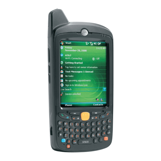
Chapter 1 Getting Started Introduction This chapter lists the parts and accessories for the MC55 and explains how to set up the MC55 for the first time. Radio Status LED (MC5574 Charging/Battery Scan/Decode Touch Screen with only) Status LED Protective Overlay... -
Page 20: Unpacking
Inspect the equipment for damage. If any equipment is missing or damaged, contact the Motorola Enterprise Mobility Support center immediately. See page xv for contact information. Prior to using the MC55 for the first time, remove the protective shipping film that covers the scan window, display and camera window. -
Page 21: Accessories
MC55 with a host computer through a USB connection. Single Slot CRD5500-1000XR Charges the MC55 main battery and a spare battery. Synchronizes Ethernet/Modem/USB the MC55 with a host computer through an Ethernet, Modem or USB Cradle connection. Four Slot Charge Only CRD5500-4000CR Charges up to four MC55 devices. -
Page 22: Getting Started
KT-67525-01R Package of 3 screen protectors. Software Enterprise Mobility Developer Kits (EMDKs), available at: http://support.symbol.com. Getting Started To start using the MC55 for the first time: • Install a microSD card (optional) • Install the SIM card (MC5574 only) •... -
Page 23: Installing The Sim Card
NOTE MC5574 configuration only. GSM phone service requires a Subscriber Identification Module (SIM) card, or smart card. Obtain the card from the your service provider. The card fits into the MC55 and can contain the following information: • Mobile phone service provider account details. -
Page 24: Installing The Battery
NOTE For detailed information about WWAN activation and settings, refer to the MC55 Integrator Guide. Installing the Battery NOTE The MC55 ships with either a 2400 mAh or 3600 mAh battery. The 2400 mAh battery is shown in this installation procedure. -
Page 25: Charging The Battery
Battery Safety Guidelines on page 7-2. Charging the Main Battery Before using the MC55 for the first time, charge the main battery until the amber Charging/Battery Status LED remains lit (see Table 1-2 on page 1-8 for charge status indications). To charge the MC55, use a cable or a cradle with the appropriate power supply. -
Page 26: Charging Spare Batteries
Powering On the MC55 After inserting the battery or when turning the MC55 on for the first time, the splash screen displays for about a minute as the MC55 initializes its flash file system, then the calibration window appears. Note that these windows also appear upon cold boot. -
Page 27: Checking Battery Status
NOTE To check battery status, remove the MC55 from any AC power source (cradle, cables, etc.) To check the charge status of the main battery in the MC55, tap Start > Settings > System tab > Power icon to display the Power window. -
Page 28: Battery Management
Replace the battery. Battery Management Observe the following battery saving tips: • Leave the MC55 connected to AC power at all times when not in use. • Set the MC55 to turn off after a short period of non-use. •... -
Page 29: Changing The Keypad Backlight Settings
Getting Started 1 - 11 Changing the Keypad Backlight Settings To change the keypad backlight settings in order to conserve more battery power: Tap Start > Settings > System tab > Keylight icon > Battery Power tab. Select the On battery power: Disable keylight if device if not used for check box and select a value from the drop-down list. - Page 30 1 - 12 MC55 User Guide Wireless Manager Window Figure 1-10 NOTE Wireless connection options vary depending upon configurations. To enable or disable a wireless connection, tap the specific button. To enable or disable all wireless connections, tap and hold the All button.
-
Page 31: Handstrap Replacement
Getting Started 1 - 13 Handstrap Replacement Removal To remove a handstrap from the MC55: Slide the handstrap clip out of the handstrap slot. Handstrap Clip Removal Figure 1-12 Remove the battery. CAUTION When removing handstrap pin, be carefully not to damage handstrap mounting area. -
Page 32: Installation
Repeat for the other side of the handstrap. Remove pin from the handstrap. Pin Removal Figure 1-14 Pull handstrap through handstrap slot. Installation To install a new handstrap: Feed bottom end of handstrap into handstrap slot on the bottom of the MC55. - Page 33 Getting Started 1 - 15 Feed handstrap into Handstrap Slot Figure 1-15 Slide pin into bottom of handstrap. Center the pin in the handstrap loop. NOTE Handstrap and pin should fit securely into the handstrap mounting area. When pulling on handstrap use enough force to engage pin into place.
- Page 34 1 - 16 MC55 User Guide...
-
Page 35: Chapter 2 Using The Mc55
Chapter 2 Using the MC55 Introduction This chapter explains the buttons, status icons, and controls on the MC55, and provides basic instructions for using the MC55, including powering on and resetting the MC55, and entering and capturing data. Today Screen The Today screen displays important information, such as upcoming appointments and status indicators. -
Page 36: Status Icons
2 - 2 MC55 User Guide Status Icons The Navigation bar at the top of the screen can contain the status icons listed in Table 2-1. Status Icons Table 2-1 Icon Function Description Notification Notification that one or more instant messages were received. - Page 37 Indicates the Bluetooth radio is connected to another Bluetooth device. (Available when StoneStreet One Bluetooth stack is enabled.) ActiveSync Indicates an active serial connection between the MC55 and the host computer. USB Client Mode Indicates that the MC55 is in USB Client mode.
-
Page 38: Programs
Description ActiveSync Synchronize information between the MC55 and a host computer or the Exchange Server. AirBEAM Allows specially designed software packages to be transferred between a host server and the MC55. Refer to the MC55 Integrator Guide for more information. - Page 39 Pictures & Videos View and manage pictures, animated GIFs, and video files. Rapid Deployment Facilitates software downloads from a Mobility Services Platform Console Client FTP server to the MC55. Refer to the Mobility Services Platform 3.2 User Guide for more information.
-
Page 40: Settings
Use this mobile version of Windows Live™ to find information on the web. Windows Media Play back audio and video files. Settings Table 2-5 lists control applications pre installed on the MC55. Tap Start > Settings to open the Settings window. Settings in the Setting Window Table 2-5 Icon Name Description... - Page 41 Set the appropriate GPS communication ports, if required. You may need to do this when there are programs on your device that access GPS data or you have connected a GPS receiver to the MC55. GPS Setup View GPS SUPL information.
- Page 42 Check battery power and set the time-out for turning off the display to conserve battery power. Regional Settings Set the regional configuration to use, including the format for displaying numbers, currency, date, and time on the MC55. Remove Programs Remove programs that you installed on the MC55. Screen Change the screen orientation, re-calibrate the screen, and change the screen text size.
- Page 43 Make your device an AD domain member for device management and security. USB to PC Enables or disables the enhanced network connectivity. Wi-Fi Setup wireless network connection and customize settings. Wireless Manager Enables or disables the MC55’s wireless radios and customizes Wi-Fi and Bluetooth and Phone settings.
-
Page 44: Adjusting Volume
2 - 10 MC55 User Guide Adjusting Volume To adjust the system volume using the Speaker icon in the navigation bar: Tap the Speaker icon. The Volume dialog box appears. Volume Dialog Box Figure 2-2 Tap and move the slide bar to adjust the volume. -
Page 45: Battery Reserve Options
Figure 2-5 Battery Reserve Options If the charge of the battery reaches a critical threshold, the MC55 shuts down. This threshold can be changed but affects the amount of time that data can be retained. Tap Start > Settings > System tab > Power icon > RunTime tab. A warning message appears. -
Page 46: Main Battery Temperature Notifications
• Level 3: Temperature Error; this level indicates the battery has reached an unusable temperature threshold and immediately suspends the MC55. This level does not have any graphical notification associated with it. Main Battery Temperature Watch Dialog Box Figure 2-8... -
Page 47: Led Indicators
LED Indicators The MC55 has three LED indicators. The Scan/Decode LED indicates status for scanning. The Charging/Battery Status LED indicates battery charging and status.The Radio Status LED indicates WWAN radio status. Table 2-6 describes the LED indications. -
Page 48: Resetting The Mc55
A cold boot also restarts the MC55, and also initializes some drivers. Data saved in flash memory or a memory card is not lost. If the MC55 is not functioning properly, perform a warm boot first. If the MC55 still does not respond, perform a cold boot. -
Page 49: Locking The Mc55
You can lock the MC55 by disabling key presses and screen tap or by requiring a password. Keypad Locking Locking the MC55 turns off keyboard and touch screen functionality. This is helpful when the MC55 is turned on and you want to prevent accidental key presses. -
Page 50: Password Locking
Making an Emergency Call on page 4-8 for more information. Password Locking Use the Password window to set a password to disable unauthorized access to the MC55. If the device is configured to connect to a network, use a strong (difficult to figure out) password NOTE to help protect network security. - Page 51 Figure 2-14 In the text box, enter a hint for a password reminder. Tap ok. When the MC55 is not used for a period of time and the user tries to access the device, the Password window appears. Enter Password Windows Figure 2-15 Enter the password to un-lock the device.
-
Page 52: Keypads
2 - 18 MC55 User Guide Keypads The MC55 offers three types modular keypad configurations: Numeric, alpha-numeric and PIM. Numeric Keypad Configuration The numeric keypad contains application keys, scroll keys, and function keys. The keypad is color-coded to indicate the alternate function key (blue) values. Note that an application can change keypad functions so the MC55’s keypad may not function exactly as described. - Page 53 [where xx is the new APP key code] Provision the file to the MC55 to send an APP key code, instead of the original key code, upon pressing the green phone key. Refer to the MC55 Integrator Guide for information on creating XML provisioning files.
- Page 54 2 - 20 MC55 User Guide MC55 Numeric Keypad Descriptions (Continued) Table 2-8 Description Soft Keys Accesses the command or menu above it on the screen. Star Produces an asterisk in default state. Press and release the orange key, then press the Star key to create special characters. See Special Character Key on page 2-31 for more information.
-
Page 55: Alpha-Numeric Keypad Configurations
Using the MC55 2 - 21 Numeric Keypad Input Modes Table 2-9 Orange Key Orange + Shift Keys Numeric Mode (Alpha Lowercase Mode) (Alpha Uppercase Mode) Blue+ SHIFT + Key Press Press Press Press Press Press Press Press & >... - Page 56 2 - 22 MC55 User Guide QWERTY Keypad Configuration Figure 2-17 AZERTY Keypad Configuration Figure 2-18 QWERTZ Keypad Configuration Figure 2-19...
- Page 57 [where xx is the new APP key code] Provision the file to the MC55 to send an APP key code, instead of the original key code, upon pressing the green phone key. Refer to the MC55 Integrator Guide for information on creating XML provisioning files.
- Page 58 [where yy is the new APP key code] Provision the file to the MC55 to send an APP key code, instead of the original key code, upon pressing the red phone key. Refer to the MC55 Integrator Guide for information on creating XML provisioning files.
- Page 59 Using the MC55 2 - 25 Alpha-numeric Keypad Descriptions (Continued) Table 2-10 Action Enter Executes a selected item or function. Star Produces an asterisk. Creates special characters. QWERTY Keypad Input Modes Table 2-11 Normal Shift + Key Orange + Key Blue + Key “...
- Page 60 2 - 26 MC55 User Guide QWERTY Keypad Input Modes (Continued) Table 2-11 Normal Shift + Key Orange + Key Blue + Key ‘ Backspace Backspace Backspace Backspace Backspace Shift Shift Shift-Lock Shift Shift & < ENTER Enter Enter Enter...
- Page 61 Using the MC55 2 - 27 AZERTY Keypad Input Modes (Continued) Table 2-12 Normal Shift + Key Orange + Key Blue + Key áü ‘ Backspace Backspace Backspace Backspace Backspace Shift Shift Shift-Lock Shift Shift & < Enter Enter Enter...
-
Page 62: Qwertz Keypad Input Modes
2 - 28 MC55 User Guide QWERTZ Keypad Input Modes Table 2-13 Normal Shift + Key Orange + Key Blue + Key “ áü ‘ Backspace Backspace Shift Shift & < Note: An application can change the key functions. The keypad may not function exactly as described. -
Page 63: Pim Keypad Configuration
Note: An application can change the key functions. The keypad may not function exactly as described. PIM Keypad Configuration The PIM keypad contains application keys and scroll keys. Note that an application can change keypad functions so the MC55’s keypad may not function exactly as described. See Table 2-8 for key and button descriptions and Table 2-9 on page 2-21 for the keypad’s special functions. - Page 64 [where xx is the new APP key code] Provision the file to the MC55 to send an APP key code, instead of the original key code, upon pressing the green phone key. Refer to the MC55 Integrator Guide for information on creating XML provisioning files.
-
Page 65: Special Character Key
NOTE Special characters are only available on the alpha-numeric keypad configurations. To add special characters using the MC55 áü key, type the related character first, then press the Orange twice followed by the áü (P) key. Continue pressing the áü key until the special character displays. To modify an existing character, move the cursor to the right of the character then press the Orange key twice and then press the áü... - Page 66 2 - 32 MC55 User Guide Special Characters (Continued) Table 2-15 Special Characters Special Characters “ & ‘...
-
Page 67: Function Buttons
Function Buttons Figure 2-21 • Power: Press the red Power button to turn the MC55 screen on and off. The MC55 is in suspend mode when the screen is off. For more information, see Powering On the MC55 on page 1-8. -
Page 68: Entering Data
2 - 34 MC55 User Guide Entering Data When entering data on the keypad, use either the single-hand method or the two-hand method as shown in Figure 2-22. Two-hand Method Single-hand Method Entering Data on the Keypad Figure 2-22... -
Page 69: Data Capture
Pick List Mode: This mode allows you to selectively decode a bar code when more than one bar code is in the MC55’s field of view. To accomplish this, move the aiming crosshair or dot over the required bar code to decode only this bar code. -
Page 70: Digital Camera
Hold the MC55 farther away for larger symbols. • Move the MC55 closer for symbols with bars that are close together. NOTE Scanning procedures depend on the application and MC55 configuration. An application may use different scanning procedures from the one listed above. Linear Scanning Ensure that a scan enabled application is loaded on the MC55. -
Page 71: Imager Scanning
Correct Incorrect Linear Scanner Aiming Pattern Figure 2-24 Imager Scanning Ensure that a scan-enabled application is loaded on the MC55. Aim the scan window at the bar code. SE4500 (MC5590 only) SE4400 SE4400 Imager Scanning Figure 2-25... - Page 72 The Scan/Decode LED lights red to indicate that scanning is in process, then lights green and a beep sounds, by default, to indicate the bar code was decoded successfully. Note that when the MC55 is in Pick List Mode, the imager does not decode the bar code until the crosshair or aiming dot touches the bar code.
-
Page 73: Using The Rs507 Hands-Free Imager
Tap Start > Programs > BD Address icon. A bar code displays. Point the RS507 to the bar code. The RS507 reads the bar code and begins pairing with the MC55. Refer to the RS507 Hands-free Imager Product Reference Guide for more information. -
Page 74: Using Voice-Over-Ip
Using Voice-Over-IP The MC55 supports Voice over IP over WLAN (VoWLAN) using Motorola or third party voice clients. The MC55 can communicate using VoIP either using the MC55 supports several audio outputs, including back speaker phone, front receiver or handset, and Bluetooth headset. -
Page 75: Recording Video
Using the MC55 2 - 41 Recording Video To record a video clip: Tap Start > Programs > Pictures & Videos icon. Tap Camera on the command bar. Tap Menu > Video to set shooting mode to video. The available recording time displays on the screen. - Page 76 2 - 42 MC55 User Guide...
-
Page 77: Chapter 3 Using Gps Navigation
WARNING When using the MC55 in a vehicle, it is the user’s responsibility to place, secure and use in a manner that will not cause accidents, personal injury or property damage or obstruct their view. It... -
Page 78: Operation
MC55 from receiving a GPS signal from satellites. To improve GPS signal strength, place the MC55 where there is a clear view of the sky. A direct line of sight is required between the MC55 and the GPS satellites to access information from the satellites. -
Page 79: Chapter 4 Using The Phone
Chapter 4 Using the Phone Introduction Use the MC55 to make phone calls, set up speed dials, keep track of calls, and send text messages. Your wireless service provider may also provide other services such as voice mail, call forwarding, and caller ID. -
Page 80: Turning The Phone On And Off
4 - 2 MC55 User Guide To access the phone keypad tap Start > Phone, press the left soft key or press the green phone key on the MC55’s keypad. To receive calls when the MC55 is suspended, leave the phone radio turned on and ensure the MC55 is set to wake with any key. -
Page 81: Audio Modes
The MC55 offers three audio modes for use during phone calls: • Handset Mode: Switches audio to the speaker at the top front of the MC55, so you can use the MC55 as a handset. This is the default mode. -
Page 82: Adjusting Audio Volume
Figure 4-4 Adjusting Audio Volume Use the Volume Control Slider or the volume Up/Down buttons on the side of the MC55 to adjust the volume of the ringer when not in a call and the audio volume when in a call. -
Page 83: Using Contacts
Tap End to stop dialing or end the call. NOTE Alternatively, use the green and red phone keys on the MC55 keypad to dial (green) and end (red) calls. If you tap a wrong number, tap Delete key to erase each subsequent digit of a number. To erase the entire number, tap and hold the Delete key. -
Page 84: Editing An Outlook Contact
4 - 6 MC55 User Guide Tap to return to the contact list (the contact is saved automatically) Scroll to see more fields Notes is a good place for maps and directions Creating a Contact Figure 4-7 Using the input panel, tap in each field and enter contact information as needed. Scroll down to see all fields. -
Page 85: Creating A Sim Contact
When finished, tap ok to return to the contact list. Using Call History To make a call using Call History: Tap Start > Phone or press the green phone key on the MC55’s keypad. From the Phone keypad, tap Call History. Phone icon... -
Page 86: Making A Speed Dial Call
Answering a Call A dialog box appears on the MC55 when it receives an incoming call. If the phone is set to ring, a ring tone sounds. Answer or ignore the incoming call. To answer an incoming call tap Answer on the Phone > Incoming... dialog or press the green phone key on the... -
Page 87: Incoming Call Features
If you receive a call while in a call, tap Wait to place the call in call waiting. • You can use other programs on the MC55 during a call. To switch back to Phone, tap Talk or tap Start > Phone. Tap End to end the call. -
Page 88: Muting A Call
This is useful when there is conversation or background noise on your end. To mute or unmute a call: Tap Start > Phone or press the green phone key on the MC55’s keypad. Make a call. -
Page 89: Taking Notes
Windows On-Device Help. To access a note created during a call: Tap Start > Phone or press the green phone key on the MC55’s keypad. From the Phone keypad, tap Call History. Tap and hold the number or the Note icon for the phone call entry containing the note. -
Page 90: Using Speed Dial
To add a speed dial entry from the phone keypad: Ensure the contact and phone number are in the Contacts list. Tap Start > Phone or press the green phone key on the MC55’s keypad. Tap Speed Dial > Menu > New. - Page 91 Using the Phone 4 - 13 Speed Dial Contact Location Figure 4-17 In the Location field, tap the up/down arrows to select an available location to assign as the new speed dial entry. The first speed dial location is reserved for voice mail. Tap ok to add the contact to the speed dial list.
-
Page 92: Editing A Speed Dial Entry
Tap the up/down arrows to select an available location to assign as the new speed dial entry. The first speed dial location is reserved for voice mail. Tap ok. Editing a Speed Dial Entry Tap Start > Phone or press the green phone key on the MC55’s keypad. Tap Speed Dial. -
Page 93: Deleting A Speed Dial Entry
Contacts > Deleting a Speed Dial Entry Tap Start > Phone or press the green phone key on the MC55’s keypad. Tap Speed Dial. Tap and hold the contact name. Speed Dial Delete Menu Figure 4-22 Tap Delete. -
Page 94: Using Call History
Change views, reset the call timer, and delete calls to manage the calls stored in Call History. Changing the Call History View Tap Start > Phone or press the green phone key on the MC55’s keypad to display the Phone keypad. From the Phone keypad, tap Call History. -
Page 95: Deleting Call History Items By Call Date
Tap ok to exit the Call Timers window. Deleting Call History Items by Call Date Tap Start > Phone or press the green phone key on the MC55’s keypad to display the Phone keypad. From the Phone keypad, tap Call History. -
Page 96: Deleting All Call History Items
Tap ok to exit the Call Timers window. Deleting All Call History Items Tap Start > Phone or press the green phone key on the MC55’s keypad to display the Phone keypad. From the Phone keypad, tap Call History. Tap Menu. -
Page 97: Viewing Call Status
Using the Phone 4 - 19 Viewing Call Status Tap Start > Phone or press the green phone key on the MC55’s keypad to display the Phone keypad. From the Phone keypad, tap Call History. Tap an entry. The Call Status window appears. -
Page 98: Swapping Calls
To move between two or more phone calls: Tap Start > Phone or press the green phone key on the MC55’s keypad to display the Phone keypad. Enter the first phone number and press Talk. When the call connects, Hold appears on the keypad. -
Page 99: Conference Calling
To create a conference phone session with multiple people: Tap Start > Phone or press the green phone key on the MC55’s keypad to display the Phone keypad. Enter the first phone number and press Talk. When the call connects, Hold appears on the keypad. -
Page 100: Text Messaging
160 characters. Short text messages delivered over mobile networks transmit from the sending MC55, are stored in a central short message center, then forwarded to the destination mobile device. If the recipient is not available, the message is stored and can be sent later. - Page 101 Using the Phone 4 - 23 The Caller Identification feature matches incoming text message numbers with those stored in Contacts so you know who is sending you a message. Furthermore, the New Text Message dialog box gives you the option to call the sender or save, dismiss, or delete the message.
-
Page 102: Sending A Text Message
4 - 24 MC55 User Guide In the message list, tap a text message. The window displays previous text conversations. Tap to reply the message. Text Message - Conversation Figure 4-40 To reply, enter text in the reply field and tap Send. - Page 103 Using the Phone 4 - 25 Address Area Message Area Create Text Message Figure 4-42 • The auto-correct feature automatically fixes common spelling errors as you type so your messages are more accurate. • The character counter lets you see and control the size of the message as you compose. •...
-
Page 104: Establishing A Data Connection
4 - 26 MC55 User Guide Establishing a Data Connection NOTE Refer to the MC55 Integrator Guide for information on configuring a data connection. Ensure a SIM card is installed in the MC55. Configure a GPRS data connection. See MC55 Integrator Guide for more information. -
Page 105: Ending A Data Connection
If the connection is not established the user might need to re-enter the correct APN. See the NOTE MC55 Integrator guide for information on configuring a data connection. Ending a Data Connection To cancel a data connection in progress, tap Cancel in the Connecting... dialog window. - Page 106 4 - 28 MC55 User Guide Tap Disconnect. Disconnect NOTE Tapping during an active data transfer (e.g., downloading a web page) automatically reconnects the connection. You cannot disconnect the connection until the data transfer is complete...
-
Page 107: Chapter 5 Using Bluetooth
MC55s with Bluetooth capabilities can exchange information (e.g., files, appointments, and tasks) with other Bluetooth enabled devices such as phones, printers, access points, and other mobile computers. To use the MC55 as a modem, create a dial-up modem connection between a computer and MC55. -
Page 108: Security
MC55 User Guide The Bluetooth radio in this MC55 operates as a Class 2 device power class. The maximum output power is 2.5mW and the expected range is 32.8 feet (10 meters). A definition of ranges based on power class is difficult to obtain due to power and device differences, and whether one measures open space or closed office space. -
Page 109: Bluetooth Configuration
Guide, Appendix B, for information on switching to the Microsoft Bluetooth stack. If the MC55 is configured to use the StoneStreet One Bluetooth stack, the Bluetooth icon appears at the bottom right corner of the Today screen. If the Microsoft Bluetooth stack is configured, the Bluetooth icon does not appear. -
Page 110: Bluetooth Power States
Cold Boot Performing a cold boot on the MC55 turns off Bluetooth after initialization (which takes a few moments). It is normal to see the Bluetooth icon appear and disappear, as well as a wait cursor, when initialization proceeds in all modes. -
Page 111: Using Bluetooth Stonestreet One Bluetooth Stack
Turn off the Bluetooth radio to save power or if entering an area with radio restrictions (e.g., an airplane). When the radio is off, other Bluetooth devices cannot see or connect to the MC55. Turn on the Bluetooth radio to exchange information with other Bluetooth devices (within range). -
Page 112: Explorer Mode
NOTE Switching between Wizard Mode and Explorer Mode closes all active connections. Discovering Bluetooth Device(s) The MC55 can receive information from discovered devices without bonding. However, once bonded, the MC55 and a bonded device exchange information automatically when you turn the Bluetooth radio on. See... - Page 113 Using Bluetooth 5 - 7 Tap the Bluetooth icon and select Show BTExplorer. The BTExplorer window appears. NOTE If favorite connections have already been created, the Favorites screen displays. If no favorite connections have been created, the New Connection Wizard screen displays. Tap Menu >...
- Page 114 The discovered devices display in the Select Remote Device window. Select Remote Device Window Figure 5-7 Select a device from the list and tap Next. The MC55 searches for services on the selected Bluetooth device. Device Services Figure 5-8 NOTE If the MC55 discovers a service but the service is not supported, the service icon is grayed-out.
-
Page 115: Available Services
Tap Connect to add the service to the Favorite window and connect to the service. Favorites Window Figure 5-10 Available Services NOTE Some devices might not require a PIN. This depends upon the device’s authentication. The MC55 offers the following services: • File Transfer Services • Dial-Up Networking Services •... - Page 116 File Transfer Services NOTE Shared folders are a security risk. To transfer files between the MC55 and another Bluetooth enabled device: Ensure that OBEX File Transfer profile is enabled on the MC55. See Profiles Tab on page 5-35 for more information.
- Page 117 • Delete - delete the selected file on the remote device. • Get File - copy the file from the remote device to the MC55. • Put File - copy a file from the MC55 to the remote device. Creating a New File or Folder To create a new folder or file on the remote device: Tap and hold on the screen and select New >...
-
Page 118: Connecting To The Internet Using An Access Point
NOTE Network Access profile is not supported. Dial-Up Networking Services Dial-up networking allows the user to connect a PC or laptop to the MC55 and use the MC55 as a modem to connect to an office network or ISP. Before setting up dial-up networking, obtain dial-up information and other necessary settings (username, password and domain name, if required) for the office network or ISP. -
Page 119: Object Exchange Push Services
On the PC or laptop, set up Bluetooth according to the manufacturer’s instructions. On the PC or laptop Bluetooth software, search for the MC55 and select the Dial-up Networking service. Using dial-up software on the PC or laptop, connect to the MC55. - Page 120 5 - 14 MC55 User Guide In the Action drop-down list, select one of the following options: Send Contact Information, Swap Contact Information, Fetch Contact Information, or Send a Picture. Sending a Contact To send a contact to another device: NOTE Prior to sending and receiving contacts, a default contact must be set up before attempting to send a contact.
- Page 121 NOTE Prior to swapping contacts, a default contact must be set up before attempting to send a contact. Ensure that the MC55 is connectable. Tap and hold on OBEX Object Push and select Connect. The OBEX Object Push window appears.
- Page 122 5 - 16 MC55 User Guide Fetching a Contact To fetch a contact from another device: NOTE Prior to sending and receiving contacts, a default contact must be set up before attempting to send a contact. Ensure that the MC55 is connectable.
-
Page 123: Headset Services
Use the Connection Wizard to search for a Bluetooth headset. Select the device and tap Next. Select the Headset service name and select Connect. The MC55 connects to the headset. Refer to the headset user manual for instructions on communicating with a Bluetooth device. -
Page 124: Hands-Free Services
Select the Hands-free service name and select Connect. The MC55 connects to the headset. Refer to the headset user manual for instructions on communicating with a Bluetooth device. During an active connection, the MC55 cannot go into suspend mode when the Power Button is pressed. A message appears notifying the user. -
Page 125: Activesync Using Serial Port Services
ActiveSync Connection Settings Window on PC Figure 5-22 To establish an ActiveSync connection: Ensure that the Sync profile is enabled on the MC55. See Profiles Tab on page 5-35 for more information. Use the Connection Wizard to search for a Bluetooth device, such as a PC. In the drop-down list select ActiveSync via Bluetooth. -
Page 126: Personal Area Network Services
Tap Connect. The MC55 connects to the Bluetooth device. IrMC Synchronization Services IrMC Synchronization is used to synchronize PIM contacts between a remote device and the MC55. To establish an IrMC synchronization: Ensure the MC55 is connectable (required when automatic re-connect is initiated). See... -
Page 127: Connect To A Hid Device
Tap Next. Tap Connect. Connect to a HID Device The MC55 can connect to an Human Interface Device (HID) device such as a Bluetooth keyboard: Ensure the MC55 is connectable (required when automatic re-connect is initiated). See Device Info Tab on page 5-24. -
Page 128: Bonding With Discovered Device(S)
Bonding with Discovered Device(s) A bond is a relationship created between the MC55 and another Bluetooth device in order to exchange information in a secure manner. Creating a bond involves entering the same PIN on the two devices. After creating a bond and turning on the Bluetooth radios, the devices recognize the bond and can exchange information without re-entering a PIN. - Page 129 A confirmation dialog appears. Tap Yes. Accepting a Bond When a remote device wants to bond with the MC55, enter a PIN when requested to grant permission. Ensure that the MC55 is set to discoverable and connectable. See Bluetooth Settings on page 5-24.
-
Page 130: Bluetooth Settings
1 and 16 characters. In the Device Name: text box, edit the name of the device requesting the bond, if desired. Tap OK to create the bond. The MC55 can now exchange information with the other device. Bluetooth Settings Use the BTExplorer Settings window to configure the operation of the BTExplorer application. -
Page 131: Services Tab
Using Bluetooth 5 - 25 Services Tab NOTE Ensure that the MC55 is discoverable and connectable when remote devices use MC55 services. Use the Services tab to add or delete Bluetooth services. BTExplorer Settings - Services Tab Figure 5-29 To add a service: Tap Add. - Page 132 5 - 26 MC55 User Guide BTExplorer Settings - Dial-up Networking Information Figure 5-31 Dial-up Networking Information Data Table 5-4 Item Description Service Name Displays the name of the service. Service Security Select the type of security from the drop-down list. Options are None, Authenticate, or Authenticate/Encrypt.
- Page 133 Using Bluetooth 5 - 27 BTExplorer Settings - File Transfer Information Figure 5-32 File Transfer Information Data Table 5-5 Item Description Service Name Displays the name of the service. Service Security Select the type of security from the drop-down list. Options are None, Authenticate, or Authenticate/Encrypt.
- Page 134 Headset Audio Gateway Data Table 5-7 Item Description Service Name Lists the name of the audio service. IrMC Synchronization Service The IrMC Synchronization service used to synchronize PIM contacts between a remote device and the MC55. BTExplorer Settings - IrMC Synchronization Figure 5-35...
- Page 135 Select the type of security from the drop-down list. Options are None, Authenticate, or Authenticate/Encrypt. Phonebook Select the Phonebook checkbox to allow synchronization with the MC55’s contacts. Select Read, Write, Create and/or Delete to allow phonebook permissions. OBEX Object Push Service OBEX Object Push allows other Bluetooth devices to push contacts, business cards, pictures, appointments, and tasks to the MC55.
- Page 136 5 - 30 MC55 User Guide BTExplorer Settings - Personal Area Networking Figure 5-37 Personal Area Networking Data Table 5-10 Item Description Service Name Displays the name of the service. Service Security Select the type of security from the drop-down list. Options are None, Authenticate, or Authenticate/Encrypt.
- Page 137 Using Bluetooth 5 - 31 Serial Port Services Data Table 5-11 Item Description Service Name Displays the name of the service. Service Security Select the type of security from the drop-down list. Options are None, Authenticate, or Authenticate/Encrypt. Local COM Port Select the COM port.
-
Page 138: Security Tab
5 - 32 MC55 User Guide Audio Video Remote Control Service Audio Video Remote Control hosts connections from Bluetooth devices supporting audio remote-control functionality. BTExplorer Settings - Audio Video Remote Control Figure 5-40 Audio Video Remote Control Data Table 5-13... -
Page 139: Discovery Tab
Table 5-15 Item Description Inquiry Length Sets the amount of time the MC55 takes to discover Bluetooth devices in the area. Name Discovery Mode Select either Automatic or Manual to automatically attempt to discover a Bluetooth device's name after finding the device. -
Page 140: Hid Tab
5 - 34 MC55 User Guide BTExplorer Settings - Virtual COM Port Tab Figure 5-43 Virtual COM Port Tab Data Table 5-16 Item Description COM5:Bluetooth Enable or disable COM Port 5. COM9:Bluetooth Enable or disable COM Port 9. COM11:Bluetooth Enable or disable COM Port 11. -
Page 141: Profiles Tab
Using Bluetooth 5 - 35 BTExplorer Settings - HID Tab Figure 5-44 HID Tab Data Table 5-17 Item Description Enable Key Repeat Enables key repeat functionality. Delay To increase key repeat delay, drag the Delay slider to the right. To decrease key repeat delay, drag the Delay slider to the left. -
Page 142: System Parameters Tab
Link Supervision Timeout Sets the amount of time that the MC55 will wait for a device to come back into range after it has gone out of range. If the device does not come back into range by the set time, the MC55 drops the connection. -
Page 143: Using Microsoft Bluetooth Stack
Turn off the Bluetooth radio to save power or if entering an area with radio restrictions (e.g., an airplane). When the radio is off, other Bluetooth devices cannot see or connect to the MC55. Turn on the Bluetooth radio to exchange information with other Bluetooth devices (within range). -
Page 144: Discovering Bluetooth Device(S)
Un-check the Turn On Bluetooth checkbox. Tap ok. Discovering Bluetooth Device(s) The MC55 can receive information from discovered devices without bonding. However, once bonded, the MC55 and a bonded device exchange information automatically when you turn the Bluetooth radio on. See Bonding with Discovered Device(s) on page 5-22 for more information. - Page 145 Using Bluetooth 5 - 39 Select a Bluetooth Device Figure 5-51 Tap Next. The Enter Passcode window appears. NOTE If Smart-pairing is configured and the device is requesting one of the pre-defined PINs, the Enter Passcode window does not appear. Enter Passcode Figure 5-52 Enter the Passcode on the other device.
-
Page 146: Available Services
After the passcodes have been accepted on both sides, you have a trusted (“paired”) connection. Available Services NOTE Some devices might not require a PIN. This depends upon the device’s authentication. The MC55 with Microsoft Bluetooth stack offers the following services: • OBEX Object Push Services via Beam •... - Page 147 Select Beam File. The MC55 searches for Bluetooth devices in the area. Tap Tap to send next to the Bluetooth device to send the file to. The MC55 communicates with the device and send the file. When completed, Tap to send changes to Done.
-
Page 148: Internet Sharing
When completed, Tap to send changes to Done. Internet Sharing Internet Sharing allows the user to connect a computer or laptop to the MC55 and use the MC55 as a modem to connect to an office network or ISP. -
Page 149: Hands-Free Services
Tap Next. The MC55 connects to the headset. Refer to the headset user manual for instructions on communicating with a Bluetooth device. NOTE During an active connection, the MC55 cannot go into suspend mode when the Power Button is pressed. A message appears notifying the user. -
Page 150: Activesync Using Serial Port Services
Ensure that the two devices are within 30 feet (10 meters) of one another. Tap Start > Settings > Connections tab > Bluetooth icon > Devices tab. Tap Add new device. The MC55 begins searching for discoverable Bluetooth devices in the area. Select a device from the list. - Page 151 On the Allow connections to one of the following drop-down list, select the COM port with the number you noted earlier. On the MC55, tap Start > Programs > ActiveSync. Tap Menu > Connect via Bluetooth. Synchronization is automatically initiated. The ActiveSync icon appears on the lower right corner of the Today...
-
Page 152: Phone Book Access Profile Services
To disconnect the ActiveSync connection, tap the ActiveSync icon on the Today screen. Tap Disconnect. Phone Book Access Profile Services Phone Book Access profile (PBAP) is used to synchronize contacts between a remote device and the MC55. To establish an PBAP synchronization: Ensure that Bluetooth is enabled and discoverable on both devices. -
Page 153: Chapter 6 Accessories
Four Slot Charge Only Cradle - Charges up to four MC55 devices. • Four Slot Ethernet Cradle - Charges the MC55 main battery and connects the MC55 to an Ethernet network. • Single Slot USB Cradle - Charges the MC55 main battery and a spare battery. Synchronizes the MC55 with a host computer through a USB connection. -
Page 154: Single Slot Usb Cradle
6 - 2 MC55 User Guide Single Slot USB Cradle This section describes how to use a Single Slot USB cradle with the MC55. For USB communication setup procedures refer to the MC55 Integrator Guide. The Single Slot USB Cradle: •... -
Page 155: Charging The Spare Battery
Figure 6-2 Battery Charging Indicators The Single Slot USB Cradle charges the MC55’s main battery and a spare battery simultaneously. The MC55’s charge LED indicates the status of the battery charging in the MC55. See Table 1-2 on page 1-8 charging status indications. - Page 156 6 - 4 MC55 User Guide To accomplish this, for small periods of time, the MC55 or accessory alternately enables and disables battery charging to keep the battery at acceptable temperatures. The MC55 or accessory indicates when charging is disabled due to abnormal temperatures via its LED. See...
-
Page 157: Four Slot Charge Only Cradle
Accessories 6 - 5 Four Slot Charge Only Cradle This section describes how to set up and use a Four Slot Charge Only cradle with the MC55. The Four Slot Charge Only cradle: • Provides 5.4 VDC power for operating the MC55. -
Page 158: Four Slot Ethernet Cradle
MC55 User Guide Four Slot Ethernet Cradle This section describes how to set up and use a Four Slot Ethernet cradle with the MC55. For cradle communication setup procedures refer to the MC55 Integrator Guide. The Four Slot Ethernet cradle: •... -
Page 159: Vcd5000 Vehicle Cradle
Motorola is not responsible for any loss resulting from the use of the products while driving. Removing the MC55 To remove the MC55, hold back the release lever on the cradle and pull the MC55 up and out of the cradle. -
Page 160: Battery Charging Indicators
Charge batteries in temperatures from 0°C to 40°C (32°F to 104°F). Charging is intelligently controlled by the MC55. To accomplish this, for small periods of time, the MC55 alternately enables and disables battery charging to keep the battery at acceptable temperatures. The MC55 indicates when charging is disabled due to abnormal temperatures via its LED. -
Page 161: Four Slot Battery Charger
Accessories 6 - 9 Four Slot Battery Charger This section describes how to use the Four Slot Battery Charger to charge up to four MC55 batteries. Battery Charging Connect the charger to a power source. Insert the battery into a battery charging well and gently press down on the battery to ensure proper contact. - Page 162 6 - 10 MC55 User Guide Battery LED Charging Indicators (Continued) Table 6-2 Indication Slow Blinking Amber Battery is charging. Solid Amber Charging complete. Fast Blinking Amber Charging error.
-
Page 163: Cables
To charge the MC55 battery: Connect the communication/charge cable power input connector to the Motorola approved power source. Slide the bottom of the MC55 into the connector cup end of the communication/charge cable and gently press in until it latches into the MC55. -
Page 164: Led Charge Indications
1-2 on page 1-8 for charging status indications. When charging is complete, push the two locking tab down and remove the cable from the MC55. LED Charge Indications The amber Charge LED on the MC55 indicates battery charging status. See... -
Page 165: Charging Temperature
Charge batteries in temperatures from 0°C to 40°C (32°F to 104°F). Charging is intelligently controlled by the MC55. To accomplish this, for small periods of time, the MC55 or accessory alternately enables and disables battery charging to keep the battery at acceptable temperatures. The MC55 or accessory indicates when charging is disabled due to abnormal temperatures via its LED. -
Page 166: Vehicle Holder
Do not mount the vehicle holder near the driver seat air bag deployment area. • Do not place the MC55 on top of the dashboard or anywhere without securing it in the vehicle holder. • Do not mount the vehicle holder near the passenger seat air bag deployment area. -
Page 167: Assembly
Windshield Installation Figure 6-10 Flip the lever down to create a vacuum between the suction cup and the mounting surface. Make sure that the suction bond is strong enough before proceeding to the next step. Slide the MC55 into the cradle. -
Page 168: Flat Surface Installation
Locking Tab Insert MC55 into Vehicle Holder Figure 6-11 Connect the auto charger cable to the MC55 and slide the two locking tabs up to secure the cable cup to the MC55. Connect the other end to the cigarette lighter socket. - Page 169 Vehicle Holder Mounted on Flat Surface Figure 6-13 Connect the auto charger cable to the MC55 and slide the two locking tabs up to secure the cable cup to the MC55. Connect the other end to the cigarette lighter socket.
- Page 170 6 - 18 MC55 User Guide...
-
Page 171: Chapter 7 Maintenance & Troubleshooting
Do not store or use the MC55 in any location that is dusty, damp, or wet. • Use a soft lens cloth to clean the MC55. If the surface of the MC55 screen becomes soiled, clean it with a soft cloth moistened with a diluted window-cleaning solution. -
Page 172: Removing The Screen Protector
• Quick and easy installation. Removing the Screen Protector A screen protector is applied to the MC55. Motorola recommends using this to minimize wear and tear. Screen protectors enhance the usability and durability of touch screen displays. To remove the screen protector, lift the corner using a thin plastic card, such as a credit card, then carefully lift it off the display. -
Page 173: Cleaning
Always wear eye protection. Read warning label on compressed air and alcohol product before using. If you have to use any other solution for medical reasons please contact Motorola for more information. WARNING Avoid exposing this product to contact with hot oil or other flammable liquids. If such exposure occurs, unplug the device and clean the product immediately in accordance with these guidelines. -
Page 174: Cleaning The Mc55
Dip the cotton portion of the cotton tipped applicator in isopropyl alcohol. Rub the cotton portion of the cotton tipped applicator back-and-forth across the connector on the bottom of the MC55. Do not leave any cotton residue on the connector. Repeat at least three times. -
Page 175: Cleaning Frequency
Install the battery properly. See Installing the Battery on page 1-6. properly. System crash. Perform a warm boot. If the MC55 still does not turn on, perform a cold boot. See Resetting the MC55 on page 2-14. When pressing the Battery charge is at Charge or replace the battery in the MC55. - Page 176 MC55 shuts off. MC55 is inactive. The MC55 turns off after a period of inactivity. If the MC55 is running on battery power, set this period from 1 to 5 minutes, in one-minute intervals. If the MC55 is running on external power, set this period to 1, 2, 5, 10, 15, or 30 minutes.
-
Page 177: Bluetooth Connection
Refer to the EMDK or Control Panel application. bar code. MC55 is not If the MC55 does not beep on a good decode, set the application programmed to to generate a beep on good decode. generate a beep. -
Page 178: Single Slot Usb Cradle
AC power. battery is inserted. MC55 is not seated Remove and re-insert the MC55 into the cradle, ensuring it is firmly firmly in the cradle. seated. Spare battery is not Remove and re-insert the spare battery into the charging slot, seated firmly in the ensuring it is firmly seated. -
Page 179: Four Slot Ethernet Cradle
Table 7-4 Symptom Cause Solution Attempt by the MC55 MC55 removed Wait one minute and reinsert the MC55 in the cradle. This allows to ActiveSync failed. from the cradle the cradle to attempt another synchronization. while the LED was blinking green. -
Page 180: Vehicle Cradle
Troubleshooting the Four Slot Ethernet Cradle (Continued) Table 7-4 Symptom Cause Solution Battery is not MC55 removed Replace the MC55 in the cradle. The 3600 mAh battery fully charging. from the cradle too charges in less than six hours. Tap > > >... -
Page 181: Four Slot Battery Charger
Battery is faulty. Verify that other batteries charge properly. If so, replace the faulty battery. The MC55 is not Detach and re-attach the power cable to the MC55, ensuring it is fully attached to firmly connected. power. During data Cable was Re-attach the cable and retransmit. - Page 182 7 - 12 MC55 User Guide...
-
Page 183: Appendix A Technical Specifications
Appendix A Technical Specifications MC55 Technical Specifications The following tables summarize the EDA’s intended operating environment and technical hardware specifications. MC55 MC55 EDA Technical Specifications Table A-1 Item Description Physical Characteristics Dimensions MC5574: Height: 15.2 cm (6.0 in.) Width: 7.7 cm (3.03 in.) Depth: 2.7 cm (1.10 in.) - Page 184 A - 2 MC55 User Guide MC55 EDA Technical Specifications (Continued) Table A-1 Item Description Expansion Slot User accessible microSD slot. Network Connections Full-speed USB, host or client, Bluetooth and WiFi. USB host mode available with appropriate cables only. Notification...
- Page 185 Technical Specifications A - 3 MC55 EDA Technical Specifications (Continued) Table A-1 Item Description Wireless LAN Data and Voice Communications Wireless Local Area Network ® MC5574: Dual-mode IEEE 802.11b/g (WLAN) radio ® MC5590: Tri-mode IEEE 802.11a/b/g Data Rates Supported 1, 2, 5.5, 6, 9, 11, 12, 18, 24, 36, 48, and 54 Mbps Operating Channels MC5574: Chan 1-13 (2412-2472 MHz), Chan 14 (2484 MHz) Japan only;...
- Page 186 A - 4 MC55 User Guide MC55 EDA Technical Specifications (Continued) Table A-1 Item Description Wireless Wide Area Network Quad Band GSM/ EDGE Global: 3GPP TS 51.010, GCF approved module USA: FCC Part 22, Part 24 Canada: RSS-132, RSS-133 EU: EN301 511 Australia: AS/ACIF S024.1 &...
- Page 187 Technical Specifications A - 5 MC55 EDA Technical Specifications (Continued) Table A-1 Item Description Optical Resolution 640 H x 480 V pixels (gray scale) Roll 360° Pitch Angle +/- 60° from normal Skew Tolerance +/- 50° from normal Ambient Light Total darkness to 9,000 ft.
- Page 188 A - 6 MC55 User Guide Data Capture Options Table A-2 Item Description Laser Decode Capability Code 39 Code 128 Code 93 Codabar Code 11 Discrete 2 of 5 Interleaved 2 of 5 EAN-8 EAN-13 UPCA UPCE UPC/EAN supplementals Coupon Code...
-
Page 189: Mc55 Accessory Specifications
Technical Specifications A - 7 MC55 Accessory Specifications Single Slot USB Cradle Single Slot USB Cradle Technical Specifications Table A-3 Feature Description Dimensions Height: 7.1 cm (2.80 in.) Width: 11.0 cm (4.33 in.) Depth: 15.0 cm (5.91 in.) Weight 210 g (7.41 oz) -
Page 190: Four Slot Battery Charger
A - 8 MC55 User Guide Single Slot Ethernet/Modem/USB Cradle Technical Specifications (Continued) Table A-4 Feature Description Charging Temperature 0°C to 40°C (32°F to 104°F) Humidity 5% to 95% non-condensing Drop 76.2 cm (30.0 in.) drops to vinyl tiled concrete at room temperature... -
Page 191: Four Slot Ethernet Cradle
Technical Specifications A - 9 Four Slot Charge Only Cradle Technical Specifications (Continued) Table A-6 Feature Description Power Consumption 100 watts Operating Temperature 0°C to 50°C (32°F to 122°F) Storage Temperature -40°C to 70°C (-40°F to 158°F) Charging Temperature 0°C to 40°C (32°F to 104°F) Humidity 5% to 95% non-condensing Drop... -
Page 192: Magstripe Reader
A - 10 MC55 User Guide Magstripe Reader Magstripe Reader (MSR) Technical Specifications Table A-8 Feature Description Dimensions 8.4 cm x 9.4 cm (3.3 inches x 3.7 inches) Weight 79.4 g (2.8 oz.) Interface Serial with baud rate up to 19,200... -
Page 193: Cables
Technical Specifications A - 11 Vehicle Cradle Technical Specifications (Continued) Table A-9 Feature Description Humidity 10% to 95% non-condensing Drop 76.2 cm (30.0 in.) drops to vinyl tiled concrete at room temperature Electrostatic Discharge (ESD) +/- 15 kV air +/- 8 kV contact Cables USB Charging Cable Technical Specifications Table A-10... - Page 194 A - 12 MC55 User Guide Auto Charge Cable Technical Specifications (Continued) Table A-12 Feature Description Storage Temperature -40°C to 70°C (-40°F to 158°F) Humidity 10% to 95% non-condensing Electrostatic Discharge (ESD) +/- 15 kV air +/- 8 kV contact...
-
Page 195: Appendix B Voice Quality Manager
Introduction The Voice Quality Manager (VQM) is a software package that resides on the MC55. VQM enables a set of features for Voice over WiFi (VoWiFi) calls, and a sub-set of those features for cellular line calls. The VQM user interface is designed to be intuitive and easy to use, so complex tasks such as enabling the Acoustic Echo Canceller (AEC) while a call is in progress are done with very little or no user intervention. -
Page 196: Audio Modes
B - 2 MC55 User Guide Audio Modes The MC55 can be in any one of the seven different audio modes. The mode is visually indicated by the VQM icon on the title bar. VQM icon VQM Icon in Title Bar... -
Page 197: Voice Packet Prioritization
Using the Interfaces B - 3 If the user is using a Bluetooth headset, tapping the VQM icon un-pairs the Bluetooth headset from the device causing the audio to be routed to the default mode. In VQM 2.5, there is no way to go back to the Bluetooth headset using the VQM icon if it is un-paired The only way to reconnect the Bluetooth headset to the device is by using the BTExplorer application. -
Page 198: Acoustic Echo Cancellation
B - 4 MC55 User Guide • Only the Avaya softphone is currently supported. Acoustic Echo Cancellation Acoustic Echo occurs during a voice call when the audio from the earpiece enters the microphone of the same device. This results in the person at the other end hearing back a delayed version of his/her own voice (“Echo”). -
Page 199: Glossary
Glossary API. (Application Programming Interface) An interface by means of which one software component communicates with or controls another. Usually used to refer to services provided by one software component to another, usually via software interrupts or function calls AZERTY. A standard keyboard commonly used on French keyboards. “AZERTY” refers to the arrangement of keys on the top row of keys. - Page 200 Glossary - 2 MC55 User Guide bps. See Bits Per Second. Byte. On an addressable boundary, eight adjacent binary digits (0 and 1) combined in a pattern to represent a specific character or numeric value. Bits are numbered from the right, 0 through 7, with bit 0 the low-order bit. One byte in memory is used to store one ASCII character.
- Page 201 Glossary - 3 Decode Algorithm. A decoding scheme that converts pulse widths into data representation of the letters or numbers encoded within a bar code symbol. Decryption. Decryption is the decoding and unscrambling of received encrypted data. Also see, Encryption and Key. Depth of Field.
- Page 202 IEEE Address. See MAC Address. Input/Output Ports. I/O ports are primarily dedicated to passing information into or out of the terminal’s memory. MC55 mobile computers include USB ports. Interleaved 2 of 5. A binary bar code symbology representing character pairs in groups of five bars and five interleaved spaces.
- Page 203 Mobile Computer. In this text, mobile computer refers to the MC55. It can be set up to run as a stand-alone device, or it can be set up to communicate with a network, using wireless radio technology.
- Page 204 Glossary - 6 MC55 User Guide Open System Authentication. Open System authentication is a null authentication algorithm. PAN . Personal Area Network. Using Bluetooth wireless technology, PANs enable devices to communicate wirelessly. Generally, a wireless PAN consists of a dynamic group of less than 255 devices that communicate within about a 33-foot range.
- Page 205 Glossary - 7 Soft Reset. See Warm Boot. Space. The lighter element of a bar code formed by the background between bars. Specular Reflection. The mirror-like direct reflection of light from a surface, which can cause difficulty decoding a bar code. Start/Stop Character.
- Page 206 Glossary - 8 MC55 User Guide TFTP. (Trivial File Transfer Protocol) A version of the TCP/IP FTP (File Transfer Protocol) protocol that has no directory or password capability. It is the protocol used for upgrading firmware, downloading software and remote booting of diskless devices.
- Page 207 Index Numerics ActiveSync icon ........2-3 1-D bar codes .
- Page 208 Index - 2 MC55 User Guide bonding ....... 5-22 conference call ......4-21 deleting bonded device .
- Page 209 Index - 3 charging ....... 6-6 keypads ........xii charging indicators .
- Page 210 Index - 4 MC55 User Guide call swapping ......4-20 Single Slot USB Cradle ..... . . 6-1 conference call .
- Page 211 Index - 5 using Bluetooth headset ..... . 4-3 using stylus ....... 2-33 vehicle cradle .
- Page 212 Index - 6 MC55 User Guide...
- Page 214 1-800-927-9626 http://www.motorola.com/enterprisemobility MOTOROLA and the Stylized M Logo and Symbol and the Symbol logo are registered in the U.S. Patent and Trademark Office. All other product or service names are the property of their registered owners. © Motorola, Inc. 2010...