Table of Contents
Advertisement
Postfach 17 03 51, D-33703 Bielefeld • Potsdamer Straße 190, D-33719 Bielefeld
Phone + 49 (0) 5 21 / 9 25-00 • Fax + 49 (0) 5 21 / 9 25 24 35 • www.duerkopp-adler.com
Ausgabe / Edition: 04/2006
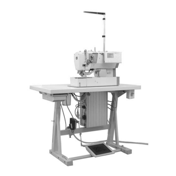
CNC double lockstitch buttonholer
Printed in Federal Republic of Germany
Manual, complete
540 - 100
Operating Instructions
Installation Instructions
Service Instructions
Teile-Nr./Part.-No.: 0791 540001
1
2
3
Advertisement
Table of Contents

Related Manuals for DURKOPP ADLER 540 - 100


Summary of Contents for DURKOPP ADLER 540 - 100
-
Page 1: Operating Instructions
Manual, complete 540 - 100 CNC double lockstitch buttonholer Operating Instructions Installation Instructions Service Instructions Postfach 17 03 51, D-33703 Bielefeld • Potsdamer Straße 190, D-33719 Bielefeld Phone + 49 (0) 5 21 / 9 25-00 • Fax + 49 (0) 5 21 / 9 25 24 35 • www.duerkopp-adler.com... - Page 2 540 - 100 Manual, complete Contents Operating Instructions Installation Instructions Service Instructions Interconnection-diagram 9890 540001 B Software version A04.1 B04.1...
- Page 3 Foreword This instruction manual is intended to help the user to become familiar with the machine and take advantage of its application possibilities in accordance with the recommendations. The instruction manual contains important information on how to operate the machine securely, properly and economically. Observation of the instructions eliminates danger, reduces costs for repair and down-times, and increases the reliability and life of the machine.
-
Page 4: General Safety Instructions
General safety instructions The non-observance of the following safety instructions can cause bodily injuries or damages to the machine. 1. The machine must only be commissioned in full knowledge of the instruction book and operated by persons with appropriate training. 2. -
Page 5: Table Of Contents
Index Page: Part 3: Service Instructions Class 540-100 Elements of the control panel Altering parameter values ......... 1.1.1 Numerical values . - Page 6 Index Page: Hook and needle bar Needle position ..........Reference position of the needle bar .
-
Page 7: Elements Of The Control Panel
Elements of the control panel Function If no text field is activated: – Change to the parent menu. If a text field is activated: – Change between the figures tenth, unit, ten etc. – Change between the lines in the menus. The selected line is always dark-shadowed. -
Page 8: Altering Parameter Values
1.1 Altering parameter values 1.1.1 Numerical values Numerical values can be altered as follows: Select the line with the value to be altered with the cursor keys ñ – and ò. – Actuate the OK key. The cursor flashes under a digit of the numerical value. Change between the digits with the cursor keys ï... -
Page 9: Menu Structure Technician Mode (Overview)
Menu structure technician mode (overview) Parameter Soft start Equipment X- /Y- Correction Submenu: Machine configuration Thread monitor Condensed stitches Subclasses Times Counter (totalizer) : Selection: Display German, English, Italian, Parameter Hour : Input Minute: Input Day: Machine Language Input Month: Set date/time Input Year:... -
Page 10: Submenu Machine Configuration (Overview)
2.1 Submenu machine configuration (overview) Max. speed: Input Speed basting stitches: Input Scissors is moved out: Input n-stitches b. u. bartack/bartack tension on: Input n-stitches b. l. bartack/bartack tension on: Input n-stitches b. lip there/lip tension on: Input n-stitches b. lip back/lip tension on: Input n-stitches b. -
Page 11: Calling Up The Technician Mode And Entering The Code
Calling up the technician mode and entering the code In order to get into the technician mode a code has to be entered. For this purpose please proceed as follows: – Press the F key in the sewing mode. A window for entering the code appears. –... -
Page 12: Submenu User
4.1.1 User submenu Parameter name Symbol Range Description T1.1.1 Max. speed 200 … 4000 Setting of the maximum speed in the sewing mode. The speed can be altered in steps of 100. T1.1.2 Speed basting stitches 200 … 4000 Setting of the speed for the basting stitches T1.1.3 Move out the scissors... -
Page 13: Submenu For Thread Monitor Configuration
4.1.4 Submenu for the thread monitor configuration Parameter name Symbol Range Description T1.4.1 Repair mode A, B, C Selection of the repair mode to be used. T1.4.2 Needle thread monitor 0 … 10 Number of stitches not registered by the thread breakage monitor before an error message is displayed. -
Page 14: Submenu For The Configuration Of Condensed Stitches
4.1.5 Submenu for the configuration of condensed stitches Parameter name Symbol Range Description T1.5.1 Number of stitches 0 … 9 Enter the number of condensed stitches T1.5.2 Stitch length X 0,3 … 2,0 mm Enter the stitch distance of the condensed stitches in direction X T1.5.3 Stitch length Y... -
Page 15: Submenu For The Configuration Of The Operating Elements
4.1.6 Submenu for entering machine times Parameter name Symbol Range Description T1.7.1 PedðStart 0 … 9000 ms Delay time between stepping down the pedal position 2 and the sewing motor start T1.7.2 EndðCage 0 … 9000 ms Delay time between sewing end and lifting of the cage T1.7.3 CageðRef... -
Page 16: Submenu For Test Functions
4.3 Submenu for test functions Parameter name Symbol Description T3.1 Multitest Select the submenu Multitest T3.2 Events Select the event display T3.3 DAC III Select the submenu DAC III Parameter T3.4 Data reset Submenu Reset T3.5 Memo dongle Select the submenu Memo dongle 4.3.1 Submenu Multitest Parameter name... -
Page 17: Submenu Output Test
4.3.1.1 Submenu Output test Select the output to be tested with the cursor keys ñ and ò . – – Press the OK key. The selected output is switched on / off. – The switching state of the output is indicated in the display. Outputs Function Control cylinder... -
Page 18: Submenu Automatic Input Test
4.3.1.3 Submenu Automatic input test The changes of the state of all inputs are displayed automatically. 4.3.1.4 Submenu Sewing motor test – Press the OK key in order to start the sewing motor. The sewing motor speed is displayed. With the cursor keys ñ and ò the speed can be altered in steps of –... -
Page 19: Submenu Dac Iii
4.4.2 Submenu DAC III Parameter name Symbol Description T3.3.1 Date/Time Submenu for setting the time and the date ð see chapter 4.2 (T2.2) of this instruction manual T3.3.2 Temperature Display of the current temperature inside the DAC III in °C T3.3.3 Intermediate circuit Display of the current intermediate... -
Page 20: Dongle Contents
4.4.3.1 Dongle contents Data dongle connected If a data dongle is plugged in, all 50 buttonhole programs or all 16 free contours respectively are displayed. Buttonhole programs are named as follows: Upper bartack type-Cutting length-Lower bartack type. The corresponding bartack shape is shown in the display. e.g.: A14.2A (“A”... -
Page 21: Submenu Saving
T3.5.2.4 Free contours The 16 program locations for free contours of the dongle are displayed. - Select the free contour to be loaded with the cursor keys ñ and ò. When selected the buttonhole number can be given on the machine (51 or 52). -
Page 22: Formatting
4.4.3.4 Formatting In order to be able to save buttonhole data on a data dongle this has to be formatted. A data dongle can only be used on a machine class for which it has been formatted. If you have formatted the dongle on e.g. class 540-100, you can only save buttonhole programs of the 540-100 on the dongle. -
Page 23: Knife Setting
Knife setting 5.1 Aligning the knife and adjusting the knife height Standard: The knife should penetrate the knife slot centrally. During the cutting open the knife should remain in the knife slot for a depth of 0.2 mm in its upper dead center. Setting: –... -
Page 24: Setting Of The Knife Incision Damper
5.2 Setting of the knife incision damper Standard: When switching on the knife, no loud sound should be heard. Setting: – Loosen counternut 1. – Screw out screw 2 completely, then screw in screw 2 with two rotations. – If necessary, make a fine adjustment of screw 2 corresponding to the instructions. -
Page 25: Hook And Needle Bar
Hook and needle bar 6.1 Needle position Standard: The needle (80 Nm) should have a distance of 1.8 mm to the front edge of the knife. Setting: – Loosen screw 3 through drill-hole 4 in the arm. – Shift the needle bar linkage 5 according to the instructions. –... -
Page 26: Setting The Adjusting Sheet
Standard reference position of the needle bar: – Switch the machine on and let it move to the initial position. – Switch the machine off again. Correction: – Loosen the screws 8 and shift the proximity switch 6 according to the instructions. -
Page 27: Loop Formation Stroke Position And Distance Between Hook And Needle
6.4 Loop formation stroke position and distance between hook and needle Standard : In loop formation stroke position the hook tip should be at the level of the middle of the needle. The looping stroke amounts to 2 mm ±0.2 mm up to 4 mm throw width and 2.2 mm ±0.2 mm for a throw width of more than 4 mm. -
Page 28: Needle Bar Height
6.5 Needle bar height Standard : In the furthest right entry point the hook tip in looping stroke position should be just above the eye of the needle. Setting : – Dismount the throat plate. – Bring the machine in looping stroke position. –... -
Page 29: Needle Protection
6.6 Needle protection Standard: In the furthest right needle entry point the needle protection in looping stroke position should abut on the needle without pushing it aside. Setting : – Bring the machine in looping stroke position. – The bolt of the needle bar linkage must be at the left flank of the adjusting sheet (furthest right entry point). -
Page 30: Aligning The Throat Plate As To The Needle
Aligning the throat plate as to the needle Standard: The needle should penetrate in the centre of the needle hole. Setting: – Loosen screws 3 and 4 in the throat plate. – Press the throat plate against the left stop guide and shift according to the instructions. -
Page 31: Thread Controller Spring And Thread Regulator
8.2 Thread take-up spring and thread regulator Standard: While the thread lever is moving down from its upper dead center, the thread take-up spring should hold the thread tight until the needle penetrates the fabric. Setting of the thread controller spring: –... -
Page 32: Sewing Basket
Sewing basket 9.1 Setting of the cloth presser block (lifting stroke) Standard: The maximum stroke of 12 mm must not be exceeded. When exceeding the stroke the needle thread scissors would be pressed against the knife. Setting: – Lower the sewing basket. –... -
Page 33: Alignment Of The Sewing Basket As To The Throat Plate
9.3 Alignment of the sewing basket as to the throat plate Standard: When the sewing basket is lowered, the inner window of the sewing basket should stand centrally to the needle hole. The guide roller of the cloth presser block should run centrally in the guide groove of the guide lever of the sewing basket. -
Page 34: Reference Position Of The Sewing Basket
9.4 Reference position of the sewing basket Standard: In reference position the distance between the needle and the inner edge of the cage should amount to 1 - 1.5 mm. Correction: – Switch the machine on. – Push the pedal backwards. The sewing basket is lowered. –... -
Page 35: Setting Of The Closing Path
10.1 Setting of the closing path Standard: With the bobbin thread scissors closed the cutting edges should have moved approx. 1 mm one on top of the other. Setting: – Lift the cage. – Carefully dismount the throat plate (the knife parts must not move). –... -
Page 36: Adjusting The Spring Sheet Of The Thread Rest
10.2 Adjusting the spring sheet of the thread rest Standard: The spring sheet of the thread rest must be adjusted in such a way that the thread is held in the thread rest with a very low holding force. Setting: Turn the threaded pin 7 in the support plate in order to change the holding force of the clamping sheet. -
Page 37: Needle Thread Scissors
11. Needle thread scissors 11.1 Function sequence Motional sequence Initial position – Sewing basket lifted. – The closed scissors holds the thread. – Scissors is swivelled in. Sewing position – Sewing basket lowers. – The closed scissors holds the thread clamped. –... -
Page 38: Removal And Check Of The Needle Thread Scissors
11.2 Removal and check of the needle thread scissors Standard: Before mounting and adjusting the needle thread scissors the following has to be observed: – The edges of the thread clamping plate have to be rounded and highly polished – The thread has first to be clamped and then cut by the movable part of the scissors. -
Page 39: Alignment Of The Scissors Block
11.3 Alignment of the scissors block Standard 1: The scissors block should be at the same level as the lug of the cage presser bar. Standard 2: – The scissors block should be aligned in parallel position to the sewing head edge. (3 and 4 mm throw width ) –... - Page 40 Notes:...
-
Page 41: Scissors Swivelled In
11.4 Scissors swivelled in Standard: (throw width 3 and 4 mm) When the sewing basket is lowered, there should be a distance of 0.5 mm between the front edge of the scissors and the right edge of the sewing basket. Standard: (throw width 6 mm) When the sewing basket is lowered, the edge of the bottom part of the scissors should have a distance of 0 - 0.3 mm from the left edge of the... -
Page 42: Height Adjustment
11.5 Height adjustment Standard: The needle thread scissors should not rest on the sole of the cage. (Distance approx. 0.1 mm) Setting: – Loosen threaded pin 2 with the sewing basket lowered. – Turn the axle until pin 3 lifts the scissors. –... -
Page 43: Distance To The Needle
11.7 Distance to the needle Standard: When the sewing basket is lowered, the distance between the needle thread scissors and the needle should amount to 1.3 - 1.5 mm. Setting: – Position the needle in the needle hole. – Loosen threaded pin 4 and shift the holding block until the spacing is set. -
Page 44: Setting Of The Closing Path
11.9 Setting of the closing path Standard : With the needle thread scissors closed the two cutting edges should have moved 1 mm one on top of the other. Setting: – Switch the machine on. – Select parameter T3.1.1 Outputs of the submenu Multitest and switch output Y1. -
Page 45: Machine Stop Position
Hint A too long holding of the needle thread leads to a displacement of the stitches in the seam beginning. By using the configuration of the parameter “Position last stitch” T1.5.4 in the technician level, it is possbile to set the position of the last knotting stitch of the buttonhole. -
Page 46: Bobbin Winder
13. Bobbin winder Standard: When the bobbin is full, the winding process should stop automatically. Setting: – Unscrew the cover of the case. As the bobbin winder is connected to the power supply with cables, lift the cover carefully so that the cables are not damaged. -
Page 47: Solenoid Valves
14. Solenoid valves Function test: – T3.1.1 Select the submenu Output test – The following outputs can be switched: 1 = Control cylinder 2 = Scissors cylinder 3 = Lip tension 4 = Knife cylinder 6 7 1 2 3 4 7 Exchange: –... -
Page 48: Exchange Of The Sewing Basket
15. Exchange of the sewing basket – Switch the machine off. – Reduce the sewing basket pressure. – Loosen screw 3. – Change the sewing basket and tighten screw 3 again. – Readjust spring 5 after loosening the screw 4. For larger equipment the spring 4 at the cage guide lever has to be displaced a drill-hole further. -
Page 49: Stretching The Drive Belts
16. Stretching the drive belts The drive-belts are maintenance-free and should not be restretched. – Dismount handwheel and belt protection. Stretching of the drive belt motor-arm shaft: – Loosen screws 1. – Tighten the belt by shifting the motor. – Tighten screws 1.