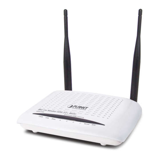
Planet ADN-4100 User Manual
802.11n wireless adsl 2/2+ router
Hide thumbs
Also See for ADN-4100:
- User manual (115 pages) ,
- Manual (2 pages) ,
- Installation manual (2 pages)
Table of Contents
Advertisement
Quick Links
Advertisement
Table of Contents

Related Manuals for Planet ADN-4100


Summary of Contents for Planet ADN-4100
- Page 1 802.11n Wireless ADSL 2/2+ Router ADN-4100 User's Manual...
- Page 2 Copyright Copyright© 2010 by PLANET Technology Corp. All rights reserved. No part of this publication may be reproduced, transmitted, transcribed, stored in a retrieval system, or translated into any language or computer language, in any form or by any means, electronic, mechanical, magnetic, optical, chemical, manual or otherwise, without the prior written permission of PLANET.
- Page 3 Reorient or relocate the receiving antenna. Increase the separation between the equipment and receiver. Connect the equipment into an outlet on a circuit different from that to which the receiver is connected. Consult the dealer or an experienced radio technician for help. FCC Caution To assure continued compliance (example-use only shielded interface cables when connecting to computer or peripheral devices).
- Page 4 Revision User’s Manual for 802.11n Wireless ADSL 2/2+ Router Model: ADN-4100 Rev: 1.0 (Sep. 2010) Part No. EM-ADN4100_v1...
-
Page 5: Table Of Contents
Contents Overview…………....................1 Safety Precautions ................1 LEDs and Interfaces ................2 System Requirements ................4 Features ....................4 Hardware Installation ..................6 Web Configuration ..................... 8 Accessing the Device ................8 General Configuration ................9 3.2.1 Wizard..................10 3.2.2 Internet Setup ................ - Page 6 3.4.5 Log Configuration ..............87 3.4.6 Logout..................88 Status....................89 3.5.1 Device Information..............89 3.5.2 Wireless Clients ................ 91 3.5.3 DHCP Clients................91 3.5.4 Logs ..................91 3.5.5 Statistics..................92 3.5.6 Route information ..............94 3.5.7 Logout..................94...
-
Page 7: Overview
Overview The ADN-4100 supports multiple line modes. It provides four 10/100Base-TX Ethernet interfaces at the user end. The device provides high speed ADSL broadband connection to the Internet or Intranet for high-end users, such as net cafes and office users. It provides high performance access to the Internet, downstream up to 24 Mbps and upstream up to 1 Mbps. -
Page 8: Leds And Interfaces
1.2 LEDs and Interfaces Front Panel Figure 1 Front panel The following table describes the LEDs of the device. Color Status Description The device is powered on and the Green initialization is normal. The power is off. The device is self-testing or self-testing is failed. - Page 9 Color Status Description transmitted in the bridge mode. The LAN connection is not established. The WLAN connection has been activated. Data is being transmitted through the WLAN Green Blinks WLAN interface. The WLAN connection is not activated. WPS is activated and the device is waiting Blinks Green for negotiation with the clients.
-
Page 10: System Requirements
Interface/Button Description seconds, it does not take effect. Press the button and hold it for 3 or more than 3 seconds, to initialize WPS negotiation. ON/OFF Power switch, power on or off the device. 1.3 System Requirements Recommended system requirements are as follows: A 10Base-T/100Base-TX Ethernet card is installed on your PC. - Page 11 Restore to the factory defaults Virtual server Three-level user accounts Web user interface Telnet CLI System status displaying PPP session PAP, CHAP, and MS-CHAP IP filter IP QoS Remote access control Line connection status test Remote management through telnet or HTTP Backup and restoration of configuration file Ethernet interface supports crossover detection, auto-correction and polarity correction...
-
Page 12: Hardware Installation
Hardware Installation Step 1 Connect the LINE interface of the device and the Modem interface of the splitter with a telephone cable. Connect the phone set to the Phone interface of the splitter through a telephone cable. Connect the input cable to the Line interface of the splitter. The splitter has three interfaces: Line: Connect to a wall phone interface (RJ-11 jack). - Page 13 Figure 3 Connection diagram (without a telephone set before the splitter) Connection 2: Figure 4 shows the connection of the device, PC, splitter, and telephone sets, when a telephone set is placed before the splitter. As illustrated in the following figure, the splitter is installed close to the device: Figure 4 Connection diagram (with a telephone set before the splitter) Note: When connection 2 is used, the filter must be installed close to the telephone...
-
Page 14: Web Configuration
Web Configuration This chapter describes how to configure the device by using the Web-based configuration utility. 3.1 Accessing the Device The following describes how to access the device for the first time in detail. Step 1 Open the Internet Explorer (IE) browser and enter http://192.168.1.1 in the address bar. -
Page 15: General Configuration
If the login information is incorrect, the page as shown in the following figure appears: Click OK to log in again. Note: In the LAN, you can use either of the following two levels of user accounts (displayed in the user name/password format) to access the device: admin/admin and user/user. -
Page 16: Wizard
3.2.1 Wizard Wizard helps you to fast and accurately configure Internet connection and other important parameters. following sections describe these various configuration parameters. When subscribing to a broadband service, be aware of the Internect connection mode. The physical WAN device can be Ethernet, DSL, or both. Technical information about properties of Internet connection is provided by your Internet service provider (ISP). - Page 17 There are four steps to configure the device. Click Next to continue. Step 3 Set the time and date. Then, click Next. Step 4 Configure the Internet connection. Select the protocol and the encapsulation mode. Set the VPI and the VCI.
- Page 18 You need to enter the user name and password for PPPoE or PPPoA dialup. If the Protocol is set to Dynamic IP, the page as shown in the following figure appears:...
- Page 19 If the Protocol is set to Static IP, the page as shown in the following figure appears: You need to enter the information of the IP address, subnet mask, and gateway. If the Protocol is set to Bridge, the page as shown in the following figure appears:...
- Page 20 If you click Scan, the system automatically searches the available PVCs. After the searching is complete, the result appears next to the Scan button.
- Page 21 After setting, click Next. Step 5 Configure the wireless network. Enter the information and click Next. Step 6 View the configuration information of the device. To modify the information, click Back. To effect the configuration, click Next.
-
Page 22: Internet Setup
Note: In each step of the Wizard page, you can click Back to review or modify the previous settings or click Cancel to exit the wizard. 3.2.2 Internet Setup Choose Setup > Internet Setup. The page as shown in the following figure appears:... - Page 23 In this page, you can configure the WAN interface of the device. Click Add and the page as shown in the following figure appears: The following table describes the parameters in this page. Field Description...
- Page 24 Field Description ATM PVC CONFIGURATION Virtual Path Identifier (VPI) is the virtual path between two points in an ATM network. Its value range is from 0 to 255. Virtual Channel Identifier (VCI) is the virtual channel between two points in an ATM network. Its value range is from 32 to 65535 (0 to 31 is reserved for local management of ATM traffic).
-
Page 25: Wireless Setup
3.2.3 Wireless Setup This section describes the wireless LAN and some basic configuration. Wireless LANs can be as simple as two computers with wireless LAN cards communicating in a pear-to-pear network or as complex as a number of computers with wireless LAN cards communicating through access points that bridge network traffic to a wired LAN. - Page 26 In this page, you can configure the parameters of wireless LAN clients that may connect to the device. The following table describes the parameters in this page. Field Description Select or deselect the check box to enable or disable Enable Wireless the wireless function.
-
Page 27: Wireless Security
Field Description value from CH1—CH13. Auto Scan is recommended. Select the 802.11 mode of the device from the 802.11 Mode drop-down list. The device supports 802.11b, 802.11g, 802.11n, 802.11b/g, 802.11n/g, and 802.11b/g/n. You can set the bandwidth only in the 802.11n mode. Band Width You can set the bandwidth of the device to 20M or 40M. - Page 28 The following table describes the parameters in this page. Field Description You can select 64 bits or 128 bits from the drop-down list. WEP Key Length If you select 64 bits, you need to enter 10 hexadecimal numbers or 5 characters.
- Page 29 Field Description If you select 128 bits, you need to enter 26 hexadecimal numbers or 13 characters. Select the WEP key from the drop-down list. Its value Choose WEP Key range is 1—4. Set the 64 bits or 128 bits key, in the format of Hex or WEP Keys 1—4 ASCII.
- Page 30 The following table describes the parameters in this page. Field Description You can select Auto (WPA or WPA2)-PSK or Auto WPA Mode (WPA or WPA2)-Enterprise from the drop-down list. Group Key Update Set the interval for updating the key. Interval Pre-Shared Key Set the preshared key to identify the workstation.
- Page 31 If the WPA Mode is set to Auto (WPA or WPA2)-Enterprise, the page as shown in the following figure appears: You need to enter the IP address, port, shared key of the RADIUS server. Click Apply to save the settings. WPA2 Only...
- Page 32 If the Security Mode is set to WPA2 only, the page as shown in the following figure appears: Parameters in this page are similar to those in the page for Auto (WPA or WPA2). Click Apply to save the settings. WPA Only If the Security Mode is set to WPA only, the page as shown in the following figure appears:...
-
Page 33: Local Network
Parameters in this page are similar to those in the page for Auto (WPA or WPA2). Click Apply to save the settings. 3.2.4 Local Network You can configure the LAN IP address according to the actual application. The preset IP address is 192.168.1.1. You can use the default settings and DHCP service to manage the IP settings of the private network. - Page 34 LAN, the IP address pool used for DHCP must be compatible with the IP address of the device. The IP address available in the DHCP IP address pool changes automatically if the IP address of the device changes. You can also enable the secondary LAN IP address. The primary and the secondary LAN IP addresses must be in different network segments.
- Page 35 By default, Enable DHCP Server is selected for the LAN interface of the device. DHCP service provides IP settings to workstations configured to automatically obtain IP settings that are connected to the device through the Ethernet port.
- Page 36 When the device is used for DHCP, it becomes the default gateway for DHCP client connected to it. If you change the IP address of the device, you must also change the range of IP addresses in the pool used for DHCP on the LAN. The IP address pool can contain up to 253 IP addresses.
-
Page 37: Time And Date
The NUMBER OF DYNAMIC DHCP CLIENTS page displays the DHCP clients (PCs or Laptops) currently connected to the device and the detailed information of the connected computers. 3.2.5 Time and Date Choose Setup > Time and Date. The TIME AND DATE page as shown in the following figure appears: In the TIME AND DATE page, you can configure, update, and maintain the time of the internal system clock. -
Page 38: Logout
Select the appropriate time server and the time zone from the corresponding drop-down lists. Select Enable Daylight Saving if necessary. Enter the correct the start and end time of the daylight saving. Click Apply to save the settings. 3.2.6 Logout Choose Setup >... -
Page 39: Advanced Settings
3.3.1.1 Advanced Settings In the ADVANCED WIRELESS page, click Advanced Settings. The page as shown in the following figure appears:... - Page 41 The following table describes the parameters in this page. Field Description ADVANCED WIRELESS SETTINGS Select the transmission rate of the wireless network Transmission Rate from the drop-down list. Select the multicast transmission rate of the wireless Multicast Rate network from the drop-down list. You can select Lower or Higher.
-
Page 42: Mac Filtering
Field Description Disable WMM Select whether to disable WMM. You can select Off or Advertise Set the maximum number of clients that can be Max Clients connected to the AP at the same time. Its value range is 1—32. SSID1—3 Enable Wireless Select or deselect the check box to enable or disable Guest Network... -
Page 43: Security Settings
The following table describes the parameters in this page. Field Description Enter the name that identifies your configuration. For User Name example, kids. Current PC’s MAC Enter the MAC address of the computer that connects Address to the device. Enter the MAC address of another device that is Other MAC Address included in MAC filtering. -
Page 44: Wps Settings
Select the desired SSID from the drop-down list. Select the encryption type from the Security Mode drop-down list. You can select None, WEP, AUTO (WPA or WPA2), WPA Only, or WPA2 Only. For parameters of different encryption types, see section.3.2.3.2 Wireless Security Click Apply to save the settings. - Page 45 Enabled: The WPS service is enabled by default. Note: Ensure that the network card supports the WPS function. You can use one of the following there methods to use WPS authentication: Press the WPS button on the side panel for 3 seconds. In the WIRELESS WPS page, click PBC.
-
Page 46: Port Forwarding
3.3.2 Port Forwarding This function is used to open ports in your device and re-direct data through these ports to a single PC in your network (WAN-to-LAN traffic). It allows remote users to access services in your LAN, such as FTP for file transfers or SMTP, and POP3 for e-mail. -
Page 48: Dmz
Select a service for a preset application or enter the name in the Custom Server field. Enter an IP address in the Server IP Address field, to appoint the corresponding PC to receive forwarded packets. The port table displays the ports that you want to open on the device. The Protocol indicates the type of protocol used by each port. -
Page 49: Parental Control
In this page, you can enable a DMZ host. In this way, access from Internet to the WAN IP address of the device is forwarded to the DMZ host and network server of the internal LAN is protected. Click Apply to save the settings. 3.3.4 Parental Control Choose Advanced >... -
Page 50: Block Website
users from accessing. Block MAC Address allows you to control Internet access by clients or PCs connected to the device. 3.3.4.1 Block Website In the PARENTAL CONTROL page, click Block Website. The page as shown in the following figure appears: Click Add. -
Page 51: Block Mac Address
3.3.4.2 Block MAC Address In the PARENTAL CONTROL page, click Block MAC Address. The page as shown in the following figure appears: Click Add. The page as shown in the following figure appears:... - Page 52 The following table describes the parameters in this page. Field Description Enter the name that identifies your configuration. For User Name example, kids. Current PC’s MAC Enter the MAC address of the computer that connects Address to the device. Enter the MAC address of another device that is Other MAC Address included in MAC filtering.
-
Page 53: Filtering Options
3.3.5 Filtering Options Choose Advanced > Filtering Options. The FILTERING OPTIONS page as shown in the following figure appears:... -
Page 54: Inbound Ip Filtering
3.3.5.1 Inbound IP Filtering In the FILTERING OPTIONS page, click Inbound IP Filtering. The INCOMING IP FILTERING page as shown in the following figure appears: Click Add to add an inbound IP filter. The page as shown in the following figure appears: Enter the Filter Name and specify at least one of the following criteria: protocol, source/destination IP address, subnet mask, and source/destination port. -
Page 55: Outbound Ip Filtering
Then, click Apply to save the settings. Note: The settings apply only when the firewall is enabled. The ACTIVE INBOUND FILTER in the INCOMING IP FILTERING page displays detailed information of each created inbound IP filter. Click Delete to delete an IP filter. -
Page 56: Bridge Filtering
Enter the Filter Name and specify at least one of the following criteria: protocol, source/destination IP address, subnet mask, and source/destination port. Click Apply to save the settings. The ACTIVE OUTBOUND FILTER in the OUTGOING IP FILTERING page displays detailed information of each created outbound IP filter. Click Delete to delete an IP filter. - Page 57 This page is used to configure bridge parameters. In this page, you can modify the settings or view the information of the bridge and its attached ports. Click Add to add a bridge filter. The page as shown in the following figure appears: The following table describes the parameters in this page.
-
Page 58: Qos Config
Field Description Source MAC Enter the source MAC address to be mapped. Address Select the frame direction to be mapped from the Frame Direction drop-down list. The device supports frame direction from LAN to WAN. Select the time that you want to apply the rule from the Time schedule drop-down list. -
Page 59: Interface Configuration
3.3.6.1 Interface Configuration In the QoS CONFIG page, click QoS Interface Config. The page as shown in the following figure appears: Click Edit and the page as shown in the following figure appears: In this page, you can configure the uplink bandwidth and downlink bandwidth of each interface. -
Page 60: Classification Configuration
In this page, you can configure the priority of the queue. The device supports the following three priority levels: high, medium, low. The device handles packets of the high queue priority first, then packets of medium, and finally packets of low priority. - Page 61 This page displays the classes. Click Add and the page as shown in the following figure appears: The following table describes the parameters in this page. Field Description Traffic Class Name Enter the name of the traffic class. Enable Select or deselect the check box to enable or disable Classification QoS classification.
-
Page 62: Firewall Settings
Field Description ethernet3, and ethernet4. Source MAC Enter the source MAC address of the packet. Address Use mask 000000ffffff to mask the MAC address. 00 Source MAC Mask indicates not mapped and ff indicates mapped. Destination MAC Enter the destination MAC address of the packet. Address Destination MAC Use mask 000000ffffff to mask the MAC address. -
Page 63: Dns
Click Apply to save the settings. 3.3.8 Domain name system (DNS) is an Internet service that translates domain names into IP addresses. Because domain names are alphabetic, they are easier to remember. The Internet, however, is actually based on IP addresses. Each time you use a domain name, a DNS service must translate the name into the corresponding IP address. -
Page 64: Dynamic Dns
The following table describes the parameters in this page. Field Description Obtain DNS server If you select this radio button, the device automatically address obtains IP address of the DNS server from the ISP. You automatically need not manually enter the IP address of the server. Use the following If you select this radio button, you need to manually DNS server... - Page 65 hostname.dyndns.org and allow remote access to a host. Many ISPs assign public IP addresses using DHCP, so locating a specific host on the LAN using the standard DNS is difficult. For example, if you are running a public web server or VPN server on your LAN, DDNS ensures that the host can be located from the Internet even if the public IP address changes.
-
Page 66: Network Tools
Field Description Select the interface that is used for DDNS service from Interface the drop-down list. The IP address of the interface corresponds to the host name. Username Enter the user name of your DDNS account. Password Enter the password of your DDNS account. Click Apply to save the settings. - Page 68 This page contains the following function items: Port Mapping, IGMP Proxy, IGMP Snooping, UPnP, ADSL, SNMP, TR-069, Certificates, PPTP, and IPSEC. 3.3.10.1 Port Mapping In the NETWORK TOOLS page, click Port Mapping. The page as shown in the following figure appears: In this page, you can bind the WAN interface and the LAN interface to the same group.
-
Page 69: Igmp Proxy
To create a mapping group, do as follows: Step 1 Enter the group name. Step 2 Select interfaces from the Available Interfaces list and click the <- arrow button to add them to the Grouped Interfaces list, in this way, you can create the required mapping of the ports. -
Page 70: Igmp Snooping
IGMP proxy enables the device to issue IGMP host messages on behalf of hosts that the system discovered through standard IGMP interfaces. The device serves as a proxy for its hosts after you enable the function. Select Enable IGMP Proxy and select the desired WAN and corresponding LAN interface. -
Page 71: Adsl Settings
3.3.10.4 UPnP In the NETWORK TOOLS page, click Upnp. The page as shown in the following figure appears: In this page, you can enable universal plug and play (UPnP) and then the system serves as a daemon. UPnP is widely applied in audio and video software. It automatically searches devices in the network. - Page 72 In this page, you can select the ADSL modulation. Normally, you are recommended to keep the factory defaults. The device supports the following modulation types: G.Dmt, G.lite, T1.413, ADSL2, AnnexL, ADSL2+, and AnnexM. The device negotiates the modulation mode with the DSLAM. Click Apply to save the settings.
- Page 73 In this page, you can set the SNMP parameters. The following table describes the parameters in this page. Field Description Select or deselect the check box to enable or disable Enable SNMP Agent SNMP agent. Universal character to obtain the device information. It Read Community is similar to the password.
- Page 74 3.3.10.7 TR-069 In the NETWORK TOOLS page, click TR-069. The page as shown in the following figure appears: In this page, you can configure the TR-069 CPE. The following table describes the parameters in this page. Field Description You can select Disabled or Enabled to disable or enable notification.
- Page 75 Field Description The user name that the devices uses to log in to the ACS User Name TR069 server. The password that the devices uses to log in to the ACS Password TR069 server. Select the check box to enable authentication of Connection Request connection request.
- Page 76 Click Input Certificate to import a certificate. The page as shown in the following figure appears: 3.3.10.9 PPTP The Point-to-Point Tunneling Protocol (PPTP) is a method for implementing virtual private networks. PPTP uses a control channel over TCP and a GRE tunnel operating to encapsulate PPP packets.
- Page 77 The following table describes the parameters in this page. Field Description Local IP Start The started IP address of the local network. The valid numbers of local IP addresses. It works Local IP Num together with the Local IP Start to determine the range of the local IP addresses.
- Page 78 The following table describes the parameters in this page. Field Description The user name that is used for dialup to connect the Username modem to the PPTP. The password that is used for dialup to connect the Password modem to the PPTP. 3.3.10.10 IPSEC In the NETWORK TOOLS page, click IPSEC.
- Page 80 Field Description IPSec Connection The connection name of the marker IPSec. Name Tunnel Mode You can select ESP or AH. Remote IPSec The IP or domain name of the Remote IPSec Gateway Address Gateway. Tunnel access from You can select Subnet or Single Address. local IP address If you select Single Address, it allows only one PC from local to connect remote hosts with IPSEC...
-
Page 81: Routing
Field Description You can select from the drop-down list. Integrity Alogorithm You can select from the drop-down list. Diffie-Hellman Group Key Exchange Key Life Time Enter the time of key life. Use Interface Select the use interface This is a dynamic page. The displays are different (some options are shown and hidden) when different types or connections are chosen. - Page 82 This page contains the following function items: static route, default gateway, and RIP settings. 3.3.11.1 Static Route Choose Advanced > Routing and click Static Route. The page as shown in the following figure appears: This page displays the information of existing static routes. Click Add and the page as shown in the following figure appears:...
-
Page 83: Default Gateway
The following table describes the parameters in this page. Field Description Destination Network The destination IP address of the device. Address Subnet Mask The subnet mask of the destination IP address. Use Gateway IP The gateway IP address of the device. Address Select the interface of the static routing used by the Use Interface... - Page 84 In this page, you can select Enable Automatic Assigned Default Gateway, or enter the information in the Use Gateway IP Address and Use Interface fields. Click Apply to save the settings. 3.3.11.3 RIP Settings Choose Advanced > Routing and click RIP. The page as shown in the following figure appears: In this page, you can view the interfaces on your device that use RIP and the version of the protocol used.
-
Page 85: Schedules
3.3.12 Schedules Choose Advanced > Schedules. The page as shown in the following figure appears: Click Add to add a schedule rule. The page as shown in the following figure appears: The following table describes the parameters in this page. Field Description Name... -
Page 86: Logout
Click Apply to save the settings. 3.3.13 Logout Choose Advanced > Logout. The page as shown in the following figure appears: Click Logout to log out of the configuration page. 3.4 Management 3.4.1 System Choose Management > System Management. The System page as shown in the following figure appears:... - Page 87 In this page, you can restart the device, back up the current settings to a file, update the backup file, and restore the factory default settings. The following table describes the buttons in this page. Button Description Reboot Restart the device. Specify the path to back up the current configuration in Backup Setting a configuration file on your computer.
-
Page 88: Firmware Update
Button Description of the device. Restore Default Reset the device to default settings. Setting Caution: Do not turn off your device or press the Reset button when the procedure is in progress. 3.4.2 Firmware Update Choose Management > Firmware Update. The page as shown in the following figure appears: In this page, you can upgrade the firmware of the device. -
Page 89: Access Controls
Step 3 Click Update Firmware to update the configuration file. The device loads the file and reboots automatically. Caution: Do not turn off your device or press the Reset button when the procedure is in progress. 3.4.3 Access Controls Choose Management > Access Controls. The ACCESS CONTROLS page as shown in the following figure appears: This page contains Account Password, Services, and IP Address. - Page 90 In this page, you can change the password and set the time for automatic logout. You are recommended to change the default password to ensure the security of your network. Ensure that you remember the new password or write it down and keep it in a safe location for future reference.
- Page 91 Field Description Set the time after which the system automatically exits Web Idle Time Out the configuration page. Its value range is 5—30 minutes. Click Apply to apply the settings. 3.4.3.2 Services In the ACCESS CONTROLS page, click Services. The page as shown in the following figure appears: In this page, you can enable or disable the services that are used by the remote host.
- Page 92 3.4.3.3 IP Address In the ACCESS CONTROLS page, click IP Address. The page as shown in the following figure appears: In this page, you can configure the IP address in the access control list (ACL). If ACL is enabled, only devices of the specified IP addresses can access the device.
-
Page 93: Diagnostics
3.4.4 Diagnostics Choose Management > Diagnosis. The page as shown in the following figure appears: In this page, you can test the connection status of the device. Click Return Diagnostic Test to run diagnostics. The page as shown in the following figure appears: 3.4.5 Log Configuration... -
Page 94: Logout
In this page, you can enable the log function. You can set Mode to Local, Remote, or Both. Local indicates to save the log in the local computer. Remote indicates to send the log to the remote log server. Both indicates to save the log in the local computer and the remote log server. -
Page 95: Status
Click Logout to log out of the configuration page. 3.5 Status In the Status page, you can view the system information and monitor the performance of the device. 3.5.1 Device Information Choose Status > Device Info. The page as shown in the following figure appears:... - Page 96 The page displays the summary of the device status, including the system information, WAN connection information, wireless information, and local network information.
-
Page 97: Wireless Clients
3.5.2 Wireless Clients Choose Status > Wireless Clients. The page as shown in the following page appears: The page displays authenticated wireless stations and their statuses. 3.5.3 DHCP Clients Choose Status > DHCP Clients. The page as shown in the following page appears: This page displays all client devices that obtain IP addresses from the device. -
Page 98: Statistics
This page displays the system log. Click Refresh to refresh the system log shown in the box. 3.5.5 Statistics Choose Status > Statistics. The page as shown in the following figure appears:... - Page 99 This page displays the statistics information of the network and data transmission. The information helps technicians to identify whether the device is functioning properly. The information does not affect the functions of the device.
-
Page 100: Route Information
3.5.6 Route information Choose Status > Route Info. The page as shown in the following figure appears: The table displays destination routes commonly accessed by the network. 3.5.7 Logout Choose Staus > Logout. The page as shown in the following figure appears: Click Logout to log out of the configuration page. -
Page 101: Ec Declaration Of Conformity
: ADN-4100A / ADN-4100B * Produced by: Manufacturer‘s Name : Planet Technology Corp. Manufacturer‘s Address : 10F, No. 96, Minquan Rd., Xindian Dist., New Taipei City 231, Taiwan, R.O.C. is herewith confirmed to comply with the requirements set out in the Council Directive on the Approximation of the Laws of the Member States relating to 1999/5/EC R&TTE.