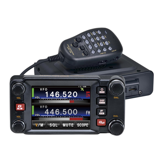
Yaesu FTM-400DR Operating Manual
C4fm fdma 144/430 mhz dual band digital transceiver
Hide thumbs
Also See for FTM-400DR:
- Operating manual (219 pages) ,
- Instruction manual (97 pages) ,
- Firmware update instruction manual (19 pages)
Table of Contents
Advertisement
FC C
I D :
K 6 6 2 0 3 4 5 X 4 0
I C :
5 1 1 B - 2 0 3 4 5 X 4 0
C4FM FDMA 144/430 MHz
DUAL BAND DIGITAL TRANSCEIVER
FTM-400DR
O
M
PERATING
ANUAL
YAESU MUSEN CO., LTD.
Tennozu Parkside Building
2-5-8 Higashi-Shinagawa, Shinagawa-ku, Tokyo 140-0002 Japan
YAESU USA
6125 Phyllis Drive, Cypress, CA 90630, U.S.A.
YAESU UK LTD.
Unit 12, Sun Valley Business Park, Winnall Close
Winchester, Hampshire, SO23 0LB, U.K.
YAESU HK LTD.
Unit 1306-1308, 13F., Millennium City 2, 378 Kwun Tong Road,
Kwun Tong, Kowloon, Hong Kong
Advertisement
Table of Contents

Related Manuals for Yaesu FTM-400DR


Summary of Contents for Yaesu FTM-400DR
- Page 1 5 1 1 B - 2 0 3 4 5 X 4 0 C4FM FDMA 144/430 MHz DUAL BAND DIGITAL TRANSCEIVER FTM-400DR PERATING ANUAL YAESU MUSEN CO., LTD. Tennozu Parkside Building 2-5-8 Higashi-Shinagawa, Shinagawa-ku, Tokyo 140-0002 Japan YAESU USA 6125 Phyllis Drive, Cypress, CA 90630, U.S.A. YAESU UK LTD.
-
Page 2: Table Of Contents
Before Using This Equipment Contents K6620345X40 511B-20345X40 Before Using This Equipment ......... 3 Programmable Memory Scan (PMS) ....37 Safety Precautions (Be Sure to Read) ....... 3 Writing into a Programmable Memory ..... 37 Before Transmitting Radio Waves ......8 Performing Programmable Memory Scan .. - Page 3 Recalling the Registered Preset......75 Deleting Memory Channels........76 Sorting Registered Memory Channels in Order. .. 76 Deleting Settings Configured for APRS Function............... 77 The Clone Function For copying settings to another FTM-400DR ..........77 FTM-400DR Specifications ........79...
-
Page 4: Before Using This Equipment
Before Using This Equipment K6620345X40 511B-20345X40 Safety Precautions (Be Sure to Read) Be sure to read the safety precautions to use this product safely. We are not liable for failures and other problems caused due to misuse or use of this product by you or a third party as well as the damages caused through use of this product by you or a third party except in the case where we are ordered to pay for damages under the laws. - Page 5 K6620345X40 511B-20345X40 Safety Precautions (Be Sure to Read) Do not perform transmission in a Do not solder or short-circuit the crowded place for the safety of the terminal of the battery pack. persons carrying a medical device A fire, leak, overheating, explosion, or such as a cardiac pacemaker.
- Page 6 K6620345X40 511B-20345X40 Safety Precautions (Be Sure to Read) If charging of the battery pack cannot be completed after lapse of the specified time, immediately remove the power plug of the battery charger from the outlet. A fire, leak, overheating, explosion, or ignition can result.
- Page 7 K6620345X40 511B-20345X40 Safety Precautions (Be Sure to Read) Charge the battery pack within the Before discarding the worn battery temperature range from 5°C to 35°C. pack, affix tape or the like to its Charging the battery pack outside this terminals. temperature range can cause leak, When using this product in a hybrid overheating, decrease in performance,...
- Page 8 K6620345X40 511B-20345X40 Safety Precautions (Be Sure to Read) About Waterproofi ng Feature Conforming to IPX5 When the included antenna and battery pack are installed and the MIC/SP jack, EXT DC IN jack, DATA terminal, and micro SD slot are securely covered with rubber caps, this product can withstand continuous 30-minute immersion in water at depth of 1 m.
-
Page 9: Before Transmitting Radio Waves
K6620345X40 511B-20345X40 Before Transmitting Radio Waves If you are informed that the radio waves emitted from your amateur station are interfering with reception by the TV, radio, etc., of a neighbor, you should stop emitting the radio waves and check whether any problem of interference and its degree if it exists. -
Page 10: Accessory And Option
K6620345X40 511B-20345X40 Accessory and Option ×××× ×××× ×××× ×××× ×××× ×××× ×××× ×××× ××××... -
Page 11: Attaching Accessory Items
K6620345X40 511B-20345X40 Attaching Accessory Items Connecting the Panel Screen to the Main Unit Connect the Panel to the Main Unit. Precaution Make sure to turn off the Main Unit when connecting the Panel Screen to the Main Unit. Connect the accessory cable to the Main Unit. -
Page 12: Setting Up The Panel Screen With The Accessory Bracket
K6620345X40 511B-20345X40 Attaching Accessory Items Setting up the Panel Screen with the accessory bracket. Set the Panel Screen up with the accessory bracket. Precaution • The bracket can be shaped by hand to fit where the Panel Screen is to be set. Be careful not to injure yourself when manipulating the bracket into the desired shape. -
Page 13: Names For Various Parts, Functional Parts And Their Functions
K6620345X40 511B-20345X40 Names for various parts, Functional Parts and their Functions. Description for Panel Screen O Pressing O shortly switches between operating bands. When selecting operating band, press the O shortly to fast forward the MHz indication. Pressing and holding O over 1 second switches the operating band in units of 5MHz v The volume can be adjusted with v. -
Page 14: Description About The Screen
K6620345X40 511B-20345X40 Names for various parts, Functional Parts and their Functions. Description about the Screen [V/M] Tapping [V/M] switches between VFO channels and Memory Channels. [SQL] Squelch level can be adjusted by tapping [SQL]. [MUTE] Tapping [MUTE] mutes reception tone. [SCOPE] Tapping [SCOPE] switches the Band Scope Function ON/OFF. - Page 15 K6620345X40 511B-20345X40 Names for various parts, Functional Parts and their Functions. ● BACK TRACK Screen [Compass Unit] Tapping [Compass Unit] saves current location information. [L1] Tapping [L1] displays location information registered to L1. [L2] Tapping [L2] displays location information registered to L2. [TX] Tapping [TX] transmits the current location information/ID/TAG of your station to the destination station.
- Page 16 K6620345X40 511B-20345X40 Names for various parts, Functional Parts and their Functions. ● ALTITUDE Screen [CLEAR] Tapping [CLEAR] deletes data being displayed. [Altitude Scale] Tapping [Altitude Scale] allows you to change measurement unit of altitude being displayed. [Distance Scale] Tapping [Distance Scale] allows you to change the measurement unit of distance being displayed.
-
Page 17: Description Of Microphone (Mh-48)
K6620345X40 511B-20345X40 Names for various parts, Functional Parts and their Functions. ● GPS INFO Screen [CURRENT] Tapping [CURRENT] displays detailed location information. [LOCATION MEMORY] Save present location information to memory. [1] Recieving Satellite Number [1] Signal Strength High [1] (Halftone 20%) Signal Strength Medium [1] (Halftone 50%) Signal Strength Low Description of Microphone (MH-48) -
Page 18: Using The Microsd Memory Card
K6620345X40 511B-20345X40 Using the microSD Memory Card Using a microSD memory card allows for the following functions. The function to backup this unit’s information. The function to save Memory Data. The function to save the Set Mode. The function to save data other than images. The function to save the GPS Log Data. -
Page 19: Precautions For When Using A Microsd Memory Card
K6620345X40 511B-20345X40 Using the microSD Memory Card Precautions for when using a microSD memory card. Do not bend or place heavy objects on top of microSD memory cards. If a microSD memory card has been formatted with a different device, may obstruct the proper storage of data. -
Page 20: Formatting The Microsd Memory Card
K6620345X40 511B-20345X40 Using the microSD Memory Card Formatting the microSD Memory Card Follow the instructions below when formatting a new microSD memory card. Precaution Formatting a microSD memory card will erase all saved data. Check the data saved to the microSD memory card in use, before formatting the card. -
Page 21: Basic Operation
Basic Operation K6620345X40 511B-20345X40 Communication Press and hold P over 1 second. Turn on the power. Adjust volume with [VOL]. Tap [SQL]. Adjust Squelch Adjust frequency using O. Reference • The frequency can also be adjusted using [UP], [DOWN], and [0] to [9] on the microphone. Speak by pressing [PTT] on the microphone. -
Page 22: Using The Timer Function
K6620345X40 511B-20345X40 Communication Using the Timer Function This unit is equipped with a Lap Timer and Down Timer. Precaution Adjust the internal clock beforehand when using the timer function.(See page 000). ● Using the Lap Timer Press M shortly. Press M shortly until clock appears. Tap [MODE]. -
Page 23: The Altitude Function For Measuring Altitude
K6620345X40 511B-20345X40 Communication Tap [START]. The Down Timer starts. Tap [STOP] to pause timer if you want to stop it in the middle. When the set time is reached, [00:00’00] appears in green. Press M shortly. Exits Timer Screen and returns to the previous screen. The ALTITUDE function for measuring altitude. - Page 24 K6620345X40 511B-20345X40 Switching type of radio (mode) and conducting communication In factory settings, this unit is set in [AUTO] mode and automatically selects the optimum mode (type of radio) according to frequency. The type of radio (mode) can be manually changed and conduct communication. Using this unit, communication can be conducted in 4 forms: [AUTO (FM)], [FM], [NARROW FM], and [AM].
-
Page 25: Changing Transmission Output
K6620345X40 511B-20345X40 Switching type of radio (mode) and conducting communication Changing Transmission Output The transmission output can be lowered for when communicating with a transceiver near by, or to reduce battery consumption. Press F. Tap [Tx PWR] and select desired transmission output. -
Page 26: Other Settings
K6620345X40 511B-20345X40 Other Settings Adjusting Time This Unit is equipped with an internal clock. Not only does this clock display time, but also has a timer for automatically turning power ON and OFF at times set by the user. Adjust the time before using this function. Press and hold M over 1 second. -
Page 27: Muting Sounds
K6620345X40 511B-20345X40 Other Settings Muting Sounds If the sounds from A Band and B Band overlap and become difficult to hear during Dual frequency reception, the sound for bands other than operating band can be muted. Press and hold M over 1 second. The Setup Menu appears. -
Page 28: Manually Switching Frequency Steps
K6620345X40 511B-20345X40 Other Settings Manually switching frequency steps In factory settings, this unit is set to [AUTO (Step)] mode and automatically selects the optimum frequency step according to reception frequency. These frequency steps can be manually changed. Press and hold M over 1 second. The Setup Menu appears. -
Page 29: Repeater Operation
511B-20345X40 Repeater Operation Communicating Via the Repeater FTM-400DR supports an ARS (Automatic Repeater Shift) function which allows you to perform communication automatically just by setting the reception frequency to the repeater frequency (439.000 to 440.000 MHz). Set the reception frequency to repeater frequency. - Page 30 K6620345X40 511B-20345X40 Repeater Operation Press and hold M over 1 second. The tone frequency is set and the screen returns to the previous one. Perform transmission while pressing [PTT]. During transmission, the tone signal that has been set and radio wave whose frequency is 5 MHz lower than the reception frequency are emitted.
-
Page 31: Using Memory
Memory content can also be erased during malfunction or repair. Content that is stored in memory should be written on paper or backed up on a microSD memory card. The FTM-400DR allows you to use 500 memory channels respectively for both A band and B band. -
Page 32: Split Memory
K6620345X40 511B-20345X40 Wide variety of Memory Functions Split Memory Two different frequencies, one for reception and other for transmission can be registered to a memory channel. Register reception frequency to the memory. Reference Refer to the [Registering to Memory] above, for registering frequency. -
Page 33: Recalling The Home Channel
K6620345X40 511B-20345X40 Wide variety of Memory Functions Recalling the Home Channel Press D shortly. Home Channels appear on screen. • Selecting the frequency with O returns to VFO Mode. Reference Returning to the Previous Frequency Press D shortly. The frequency selected before recalling the home channel appears on screen. ●... -
Page 34: Changing The Display Method Of Memory Tags
K6620345X40 511B-20345X40 Wide variety of Memory Functions Precaution Memory channel 1 cannot be deleted. Reference The memory channel specified as a home channel cannot be deleted. Before deleting it, specify another memory channel as a home channel. Changing the display method of Memory Tags. The display method of name and frequency assigned to memory tags can be changed. -
Page 35: Scanning Function
Scanning Function K6620345X40 511B-20345X40 Using the Scanning Function The FTM-400DR supports the following four scan modes: (1) VFO Scan (2) Memory Scan (3) Programmable Memory Scan (4) Selected Memory Channel Scan VFO Scan Switch to the VFO mode, and then select a band to scan. -
Page 36: Memory Scanning
K6620345X40 511B-20345X40 Using the Scanning Function Press and hold M over 1 second. The Setup Menu appears. Tap [SCAN]. Tap [3 SCAN RESUME] and select desired reception method. The reception method changes in the following order each time [3 SCAN RESUME] is tapped. [BUSY] →... - Page 37 K6620345X40 511B-20345X40 Using the Scanning Function ● Setting the Scan Method. The scanning method to scan all memory channels or only selected memory channels can be set in the Setup Menu. • ALL MEM: Scans all memory channels • SELECT MEM: Only scans selected memory channels Press and hold M over 1 second.
-
Page 38: Programmable Memory Scan (Pms)
K6620345X40 511B-20345X40 Using the Scanning Function Press and hold F over 1 second. Returns to the previous screen. (2) Individually select memory channels when scanning Switch to Memory mode and then recall the memory channels to specify as memory channels to skip or selected memory channels to scan. - Page 39 K6620345X40 511B-20345X40 Using the Scanning Function Switch to VFO mode. Select a frequency with O. Select a frequency for the lower limit. Caution • Make sure to set the frequency set for the lower limit (P1L) lower than the frequency set as the upper limit (P1U).
-
Page 40: Performing Programmable Memory Scan
K6620345X40 511B-20345X40 Using the Scanning Function Performing Programmable Memory Scan The programmable memory allows you to scan the specified frequency range in the same frequency band. Switch to Memory mode. Recall the PMS memory storing the lower limit frequency or upper limit frequency. Press F shortly. - Page 41 K6620345X40 511B-20345X40 Searching for a Signal Using a Signal Strength Graph Band Scope Function During mono band reception in the VFO mode, use states of channels (strengths of channel signals) around the current frequency set as center [▼] can be graphically displayed on screen.
-
Page 42: Useful Functions
Useful Functions K6620345X40 511B-20345X40 Dual Reception (DW) Functions This FTM-400DR supports the following two dual reception functions: (1) Dial dual reception (2) Memory dual reception The signal of the specified memory channel (Home Channel) is checked at intervals of about 5 seconds. If this signal is detected, it is received. -
Page 43: Memory Dual Reception
K6620345X40 511B-20345X40 Dual Reception (DW) Functions Memory Dual Reception → Memory channel Home Channel Switch to Memory Mode. Adjust to the memory channel to recieve. Adjust to the memory channel to receive using O knob. Press F shortly. The Function Menu appears. Tap [DW]. -
Page 44: Sending The Registered Dtmf Code
K6620345X40 511B-20345X40 Using the DTMF Function. Tap a channel to select. Select a number (1-9) to which the DTMF code is to be registered. Tap the DTMF Code to register. Tap the numerical keypad and enter the DTMF code o register. -
Page 45: Sending A Dtmf Code Manually
K6620345X40 511B-20345X40 Sending a DTMF Code Manually Press and hold M over 1 second. The Setup Menu appears. Tap [SIGNALING]. Tap [3 AUTO DIALER] and select [OFF]. Tapping [3 AUTO DIALER] switches between [ON] and [OFF]. Press and hold M over 1 second. Returns to the previous screen. -
Page 46: Communicating With A Specific Remote Station
XXXXXXXXXXXXXXXXXXXXXXXXXXXXXXXXXXX. D-TRX PRGM Turns on a new pager function (“PAG” appears). When using FTM-400DR with your friends, specifying personal codes PAGER (each code is composed of two tones) allows calling a specific station. Turns on the no-communication squelch function of the JR radio (“JR”... -
Page 47: Selecting A Tone Frequency
K6620345X40 511B-20345X40 Using the Tone Squelch Function Selecting a Tone Frequency The Tone frequency can be selected from 50 frequencies between 67.0Hz to 254.1Hz. Select the operating frequency. Press and hold M over 1 second. The Setup Menu appears. Tap [SIGNALING]. Tap [1 TONE SQL FREQ]. -
Page 48: Selecting A Dcs Code
K6620345X40 511B-20345X40 Using the Tone Squelch Function Selecting a DCS Code You can select a DCS code from among 104 DCS codes (023 to 754). Selecting the operating frequency. Press and hold M over 1 second. The Setup Menu appears. Tap [SIGNALING]. -
Page 49: Notification Of Call From A Remote Station By The Bell
When using FTM-400DR with your friends, specifying personal codes (each code is composed of two CTCSS codes) allows only a specific station to be called. Even if the called person is not near his or her FTM-400DR, the information on the screen indicates that he or she has been called. -
Page 50: Setting The Code Of Your Station
K6620345X40 511B-20345X40 Calling Only a Specific Station New Pager Function Setting the Code of Your Station Set the “personal code (your code)” used to be called by other stations. Press and hold M over 1 second. The Setup Menu appears. Tap [SIGNALING]. -
Page 51: Calling A Specific Station
K6620345X40 511B-20345X40 Calling Only a Specific Station New Pager Function Calling a Specific Station Press and hold M over 1 second. The Setup Menu appears. Tap [SIGNALING]. Tap [5 PAGER CODE]. The Pager Code Settings screen appears. Tap [TX CODE 1]. The code number appears in orange. -
Page 52: Being Called By The Remote Station (Standby Operation)
F C C I D : K 6 6 2 0 3 4 5 X 4 0 I C : 5 1 1 B - 2 0 3 4 5 X 4 0 Calling Only a Specific Station New Pager Function Being Called by the Remote Station (Standby Operation) If you use the new pager function at the same frequency as that of the remote station, [PAG] displayed on the screen changes to [PIN], allowing you to check that you have... -
Page 53: Functions Used As Needed
The Setup Menu appears. Tap [RESET/CLONE]. Tap [1 FACTORY RESET]. Tap [OK?]. Tapping [Cancel] cancels resetting. The FTM-400DR reboots. Setting content are reset and the FTM-400DR turns off once. Shortly afterwards, the FTM-400DR automatically restarts. Setup Menu Operations List Selectable Items... - Page 54 K6620345X40 511B-20345X40 Setup Menu Selectable Items Set Mode Number / Items Function Description (Bold Letter are Factory Setting Values) TX/RX DIGITAL 2 SQL TYPE OFF / CODE / BREAK 3 SQL CODE CODE: 001 to 126 4 PROFILE SEL DIGTAL / APRS / GSMS 5 PROFILE DIGITAL PROFILE: XXXXXXXXXX 6 DISTINATION MODE...
- Page 55 1 DATE & TIME ADJ Setting for the internal Date 'xx-xx-xx (xxx) clock function of the Time xx: xx FTM-400DR 2 DATE & TIME FORMAT Setting for display DATE: yyyy/mm/dd / format of the internal yyyy/dd/mm / mm/dd/yyyy / clock function...
- Page 56 FORMAT: NMEA6 / NMEA7 / NMEA8 / NMEA9 WP FILTER: ALL / MOBILE / FREQ / OBJ/ITEM / DIGI / VOIP / WEATHER / YAESU / C RINGER / R RINGER 2 DATA BAND SELECT Setting for band APRS: MAIN BAND / SUB BAND /...
- Page 57 K6620345X40 511B-20345X40 Setup Menu Selectable Items Set Mode Number / Items Function Description (Bold Letter are Factory Setting Values) APRS 1 APRS COMPASS Operation Setting for NORTH UP / HEADING UP APRS compass 2 APRS DISTINATION Display of Model Code APY100 (Fixed) 3 APRS FILTER Setting for filter function Mic-E: ON / OFF...
- Page 58 Manual position setting Latitude: x xx°xx' xx" of your station Longitude: x xxx°xx' xx" 25 MY SYMBOL Setting for the symbol of ICON1 /> Car / your station ICON2: [/R] REC.Vehicle / ICON3: [/-] House QTH (VHF) / USER: [YY] Yaesu Radios...
- Page 59 SORT: TIME / CALLSIGN / DISTANCE and Filter Function FILTER: ALL / MOBILE / FREQUENCY / OBJ/ITEM / DIGIPEATER / VOIP / WEATHER / YAESU / OTHER PKT / CALL RINGER / RNG RINGER / 1200bps / 9600bps 29 VOICE ALERT Setting for Voice Alert V.ALERT: NORMAL / TONE SQL / DCS /...
-
Page 60: Apply Settings To Contents Displayed On Screen
K6620345X40 511B-20345X40 Setup Menu Selectable Items Set Mode Number / Items Function Description (Bold Letter are Factory Setting Values) RESET/CLONE 4 MEM CH RESET Erases memory ALL MEM CH CLEAR: Only erases channels memory channels and keeps MENU content. To confirmation screen. 5 MEM CH SORT Sorts memory channels. -
Page 61: Setting The Background Color Of The Screen
K6620345X40 511B-20345X40 Setup Menu Setting the Background Color of the Screen The background color for the screen can be selected from the following 5 colors: • Green • Blue • Orange • Purple • Grey Press and hold M over 1 second. The Setup Menu appears. -
Page 62: Adjusting The Lcd Backlight Brightness Level
K6620345X40 511B-20345X40 Setup Menu Adjusting the LCD Backlight Brightness Level The brightness level of the LCD backlight can be adjusted. Press and hold M over 1 second. The Setup Menu appears. Tap [DISPLAY]. Tap [4 LCD BRICHTNESS]. The LCD Brightness Setting screen appears. Tap [–] or [+] to adjust brightness. -
Page 63: Switching Between Time And Voltage Display
K6620345X40 511B-20345X40 Setup Menu Switching between Time and Voltage display The display on the top right of the screen can be switched between [Time Display] and [Voltage Display]. Press and hold M over 1 second. The Setup Menu appears. Tap [DISPLAY]. Tap [6 TIME/VDD] and select the display content. -
Page 64: Setting The Display Method For Memory Channels
K6620345X40 511B-20345X40 Setup Menu Setting the Display Method for Memory Channels The display method for registered memory channels can be selected from the following 2 methods: • ALL: Displays all registered memory channels • INBAND: Only displays memory channels within the band currently in use. Press and hold M over 1 second. -
Page 65: Setting The Display Format For The Clock Function
K6620345X40 511B-20345X40 Setup Menu Setting the display format for the Clock Function The display format for the internal clock can be chosen from the following types: • Date Display: Month/Day/Year, Year/Month/Day, Day/Month/Year, Year/Day/Month • Time Display: 24 Hour Display, 12 Hour Display Press and hold M over 1 second. -
Page 66: Setting The Time Zone
K6620345X40 511B-20345X40 Setup Menu Setting the Time Zone The internal clock can be set to time data from GPS (Coordinated Universal Time). On Factory Settings the internal clock is set to Japan Time (UTC+9:00 TOKYO) and does not need to be adjusted. The time zone can be adjusted in 0.5 hour units for up to ±13 hours. -
Page 67: Setting The Clock Shift Of The Microcomputer
K6620345X40 511B-20345X40 Setup Menu Setting the Clock Shift of the Microcomputer You can set microcomputer clock signal so as not to receive as internal spurious by high frequency. Select [A] for normal time usage. Press and hold M over 1 second. The Setup Menu appears. -
Page 68: Setting The Bandwidth To Scope
K6620345X40 511B-20345X40 Setup Menu Setting the Bandwidth to Scope The Bandwidth for when scoping in VFO mode or Memory mode can be set. Press and hold M over 1 second. The Setup Menu appears. Tap [CONFIG]. Tap [11 RX COVERAGE] to select NORMAL/WIDE. Tapping [11 RX COVERAGE] switches between [NORMAL] and [WIDE]. -
Page 69: Automatically Turning Off The Power Apo Function
Automatically Turning Off the Power APO Function The FTM-400DR can be set so that it turns off automatically if you do not operate it for a certain period of time. You can change the time until the FTM-400DR is turned off automatically Use this function after setting the clock, referring to [Setting the Clock (See page 21)]. -
Page 70: Setting Pin Code For A Bluetooth Headset
511B-20345X40 Setup Menu Setting PIN Code for a BLUETOOTH headset Using a BLUETOOTH headset requires setting its PIN code to the FTM-400DR. Reference • The PIN code for a BLUETOOTH headset from our company is 6111. If the BLUETOOTH headset is not from our company, check the PIN code by refereeing to the instruction manual for that product. -
Page 71: Setting The Gps Device To Use
The GPS LOG Time Setting screen appears. Tap [–] or [+] to set the time. Set the time that the FTM-400DR accesses GPS. The FTM-400DR does not access GPS if [OFF] is tapped. OFF/1 sec/2 sec/5 sec/10 sec/30 sec/60 sec Press and hold M over 1 second. -
Page 72: Communicating By Crossing A Band And B Band Frequencies
• Factory Setting: OFF Setting USB Camera to Use. The FTM-400DR can capture images and video by connecting a USB camera and transmit/ receive them. You can set the picture size and quality for the USB camera you are going to use. -
Page 73: Setting Operations Of Bluetooth Headset To Use
511B-20345X40 Setup Menu Setting operations of BLUETOOTH Headset to Use You can set operations of the BLUETOOTH headset connected to the FTM-400DR. Setting content are as follows: • AUDIO: Set the audio output operation of the BLUETOOTH headset. • BATTERY: Set the battery of the BLUETOOTH headset. -
Page 74: Setting Operations Of The Voice Announcement Function
K6620345X40 511B-20345X40 Setup Menu Press and hold M over 1 second. The BLUETOOTH is set and the screenreturns to the previous one. Reference • Factory Setting: AUDIO: AUTO BATTERY: NORMAL VOX: OFF GAIN: HIGH Setting Operations of the Voice Announcement Function You can set the operations of the Voice Announcement function equipped to the FTM- 400DR. -
Page 75: Writing Group Id To Microsd Memory Card
LANGUAGE: JAPANESE VOLUME: HIGH Writing Group ID to microSD Memory Card Group ID information registered to the FTM-400DR can be written to microSD memory card. Additionally, Group ID information saved to the microSD memory card can be read to the internal memory of the FTM-400DR. -
Page 76: Registering Preset
K6620345X40 511B-20345X40 Setup Menu Registering Preset Only one current setting, such as frequency or memory channel can be registered to Preset. Press and hold M over 1 second. The Setup Menu appears. Tap [RESET/CLONE]. Tap [2 PRESET]. The Preset registration confirmation screen appears. Tap [OK?]. -
Page 77: Deleting Memory Channels
Press and hold M over 1 second. The Setup Menu appears. Tap [RESET/CLONE]. Tap [5 MEM CH SORT]. Tap [OK?]. The memory channels are sorted in order of lowest frequency. To cancel sorting, tap [Cancel]. The FTM-400DR restarts_. The FTM-400DR turns off once, then restarts automatically. -
Page 78: Deleting Settings Configured For Aprs Function
Press and hold M over 1 second. Returns to the previous screen. The Clone Function For copying settings to another FTM-400DR Information registered to this FTM-400DR can be copied to other FTM-400DR. Additionally, information registered to other FTM-400DR can be copied to this FTM-400DR. - Page 79 • If [ERROR] appears while copying (Cloning), check the connection of the Clone cable and restart the operation from the beginning. • If copying (Cloning) is abnormally aborted due to power failure, the receiving FTM-400DR will be automatically reset all information. Check that there are no abnormalities with the power and restart...
-
Page 80: Ftm-400Dr Specifications
FTM-400DR Specifications K6620345X40 511B-20345X40 General Frequency Range: 108 - 137 MHz, 137 - 174 MHz, 174 - 222 MHz, 222 - 420 MHz, 420 - 470 MHz, 800 - 999 MHz (Cellular Blocked) 144 - 148 MHz, 430 - 450 MHz Channel Steps: 5/6.25/10/12.5/15/20/25/50/100 kHz... - Page 81 K 6 6 2 0 3 4 5 X 4 0 I C : 5 1 1 B - 2 0 3 4 5 X 4 0 FTM-400DR Specifications 108 - 137 MHz: 0.80 μ V Sensitivity (for 12dB SINAD): (10 dB S/N, AM) 137 - 140 MHz: 0.20 μ...
- Page 82 K6620345X40 511B-20345X40 1. Changes or modifications to this device not expressly approved by YAESU MUSEN could void the user’s authorization to operate this device. 2. This device complies with part 15 of the FCC Rules. Operation is subject to the following two conditions;...
- Page 83 K 6 6 2 03 4 5 X 4 0 I C : 5 1 1B - 2 03 4 5 X 4 0 Copyright 2012 YAESU MUSEN CO., LTD. All rights reserved. No portion of this manual may be reproduced...