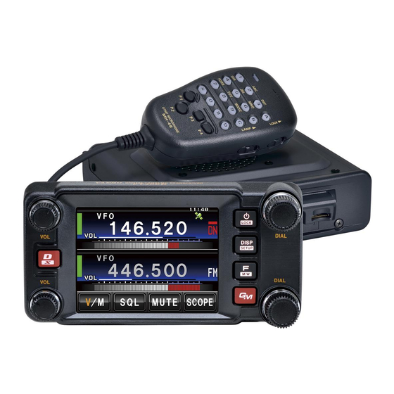
Yaesu FTM-400DR Operating Manual
Dual band transceiver c4fm fdma/fm
Hide thumbs
Also See for FTM-400DR:
- Operating manual (219 pages) ,
- Instruction manual (97 pages) ,
- Firmware update instruction manual (19 pages)

Related Manuals for Yaesu FTM-400DR


Summary of Contents for Yaesu FTM-400DR
- Page 1 FTM-400DR 144/430MHz 50W DUAL BAND TRANSCEIVER C4FM FDMA/FM Operating Manual Before Using Installation and Connection Basic Operations Using the Memory Scanning Using the GPS Function Using the APRS Function Using the GM Function Convenient Functions Functions to be used when Necessary...
-
Page 2: Introduction
LCD display. * The APRS and GM Operating Manuals are not included with the product. Please download them from the Yaesu website. Please download the WIRES-X Operating Manual from the Yaesu website when it is released. -
Page 3: Important Precautions For Mobile Radio Operation
Introduction Important precautions for mobile radio operation The use of protective tape or covering is recommended to protect the wiring and the power cord inside the vehicle. When installing the unit inside a vehicle, locate the radio, antenna, co-axial cable, etc. - Page 4 Other company and product names listed in this manual are trademarks and registered trademarks of their respective companies. Unauthorized reproduction or copying of a part or all of the copyrights owned by Yaesu Musen Co., Ltd. in any form whatsoever is strictly prohibited.
-
Page 5: How To Read This Manual
Introduction How to read this manual In this manual, controller operations are expressed as follows: Press ..........Indicates that the key or switch is to be pressed quickly. Press for 1 second or longer ..Indicates that the key or switch is to be pressed for one second or longer. -
Page 6: Table Of Contents
Introduction ..............2 Displaying the band scope ........47 Features of this radio ..........2 Muting the audio ..........48 Important precautions for mobile radio operation .. 3 Communicating............49 About the touch panel ..........4 Transmitting ............49 About registered trademarks and copyrights ..4 Adjusting the transmit power ...... - Page 7 Displaying the position information of the partner Sending saved pictures ......... 129 station in the digital mode ....... 87 Replying to a message or picture ....130 Explanation of the position information screen 88 Forwarding messages and pictures ....132 Recording the position information (GPS log ....
- Page 8 Setting the signal format ....... 174 Data communication settings ......193 Setting the transmission mode ...... 174 Setting the COM port ........193 Setting the squelch type of the digital mode . 175 Setting the operating band of the APRS and Setting the squelch code of the digital mode 176 data communication ........
- Page 9 Note beforehand that the company shall not be liable for any damages suffered by the customer or third parties in using this product, or for any failures and faults that occur during the use or misuse of this product, unless otherwise provided for under the law. This symbol indicates the possibility of death or serious injury being inflicted on the user and the surrounding DANGER...
- Page 10 Doing so may result in fire and hands. explosion. There is a risk of chemical burns occurring when the liquid comes into contact with the skin or gets into in consideration of people who are the eyes. In this case, seek medical treatment immediately.
- Page 11 power cord and connection cables Continuous exposure to loud volumes may result in hearing impairment. Please contact our company amateur and connection cables before customer support or the retail store where you purchased the device as this may result in fire, electric shock and This may result in fire, electric shock equipment failure.
- Page 12 Keep out of the reach of small children. If not, this may result in injuries to a location where there is a lot of children. The device may fall over or drop, resulting in fire, injury and equipment of the power cord and connection failure.
-
Page 13: Controller
DTMF microphone Bracket for main body Bracket for the MH-48A6JA MMB-36 controller Controller cable DC power cable Spare fuse (3 m) (with fuse attached) (15A) PC connection cable Microphone cord holder SCU-20 Operating Manual (this manual) Warranty Card Quick Manual Various optional parts are also available. -
Page 14: Front
Front ➂ ➄ ➃ ➅ ➀ ➁ ➆ ➇ ➈ ➀ VOL knob ( The volume will increase when the knob is turned in a clockwise direction and decrease when turned in an counter-clockwise direction. The upper end is for Band A use while the lower end is for Band B use. ➁... -
Page 15: Back
➆ F/MW key ( Press the button quickly to display the function menu. Press the button for 2 seconds or longer to change to the memory writing mode. ➇ Band B DIAL knob ( • The frequency of the upper band in the dual band display can be adjusted. Press the knob to enable setting the operating band frequency in 1 MHz units. - Page 16 ➁ MIC jack Plug in the provided microphone cable. ➂ DATA jack Connect MH-85A11U, the optional speaker microphone with camera. * There is no audio output available from the FTM-400DR to the MH-85A11U speaker. ➃ micro-SD card slot ➀ ➄...
- Page 17 Frequency is increased by 1 step. Frequency is decreased by 1 step. Locks / unlocks the [UP] and [DWN] keys and [P1] to [P4] keys. Turns the lamp on the body of the microphone on/off. Speak into here during transmission. Enters the numbers and letters.
- Page 18 screen ➆ ➂ ➇ ➁ ➃ ➈ ➄ ➅ ➂ ➁ ➃ ➈ ➄ ➅ ➀ Band A display area Band B display area The characters of the name tag and frequency are displayed in white for the operating band, and gray for the sub-band. ➀...
- Page 19 ● Band A and Band B will be displayed at the top and bottom. The VFO channel and memory channel will be switched by touching this symbol. The “V” is displayed in orange in the VFO mode while the “M” is displayed in orange in the memory mode.
- Page 20 The display mode will switch in the sequence each time is pressed. * This screen will be displayed when is set to “ON” in the set-up menu. ● The direction of travel of your own station and direction coordinate of the received station are displayed in the compass screen.
- Page 21 ● The altitude of the current location is shown in the bar graph display. Displays the current altitude. Represents the altitude. Represents the distance. When this symbol is touched, the scale of the distance changes. When this symbol is touched, the graph display will be cleared (erased).
- Page 22 ● The count starts when this symbol is touched. The lap time is then saved in the memory (a maximum of 99 lap times can be saved) and displayed in the upper lap display window when this symbol is touched. The lap time (of the new interval) being measured will be displayed in the lower lap display window.
- Page 23 ● The GPS satellite statuses are shown with numbered icons. Received satellite number Signal strength High Signal strength Medium Signal strength Low Input the character The keyboard screen is displayed when entering a memory channel tag or the call sign of your own station.
-
Page 24: Installation Location When Used In A Mobile Unit
Note the following when installing this radio. Do not install the radio in a place where there is extreme vibration, where there is a lot of dust, excessive humidity or high temperature, or where it is exposed to direct sunlight. Install the radio in a well ventilated position, so heat release is not obstructed because the heat sink gets hot when transmitting for a long periods of time. -
Page 25: Install The Antenna
antenna A good antenna installation is extremely important for transmission and reception purposes. Note the following, as the type and characteristics of the antenna largely determines whether the performance of the radio can be fully realized. • Use an antenna that suits the installation conditions and application objective. •... - Page 26 Create a loop (slack) in the co-axial cable directly underneath the antenna and fasten it so that the weight of the cable does not pull on the antenna or connector itself. Install the antenna taking into consideration the securing supports and how the guying wires are positioned, so that the antenna does not fall over or get blown away in strong winds.
- Page 27 Install the main body using the provided MMB-36 bracket. Select the installation location Select a location where the antenna coax and power cable can be securely attached. Also refer to “Installation location when used in a mobile unit” ( P.24). Drill four 6 mm diameter holes in the location where the bracket is to be mounted, matching the positions of the bolting holes of the bracket Attach the bracket using the provided bolts, nuts...
- Page 28 Install the controller using the provided bracket. The bracket can be bent by hand to match the location where the controller is going to be installed. Take due care not to injure yourself when bending the bracket. Select the installation location Select a stable, flat location with as few dents and protrusions as possible.
- Page 29 Make sure the power supply is switched OFF before connecting the cable between the controller and the main body. Plug the connector of the controller cable into the Main 本体 [CONTROL] jack at the front of the main body body until a click sound is heard コントロール...
- Page 30 When using this radio as a mobile unit, connect the DC power supply cable to the negative ground 12 V car battery. Use the radio in a car with a negative ground 12 V DC system, where the minus (-) pole of the battery is connected to the car body.
- Page 31 Do not use a DC power supply cable other than the one that is provided or specified. Do not rout the DC power supply cable where objects may be placed on top of it or persons may step on the cable. Do not use the DC power supply cable with the fuse holder cut off.
- Page 32 When using this radio as a fixed station, use an external 12 V DC power source. Use an external power source capable of supplying DC 13.8 V, a current capacity of 20 A or more (FTM-400DR). Make sure to switch OFF the power of the external power source before connecting.
- Page 33 Use a new micro-SD card when data can no longer be written or erased. • Note that Yaesu shall not be liable for any damages suffered as a result of data loss or corruption in use of the micro-SD card.
- Page 34 Press for 2 seconds or longer to switch off the power to the main body Insert the micro-SD card into the micro-SD card slot, micro-SD microSD with the terminal face on top, until a click sound is カードスロッ ト card slot heard Insert the micro-SD card in the correct direction.
- Page 35 When using a new micro-SD card, initialize the micro-SD card according to the following procedure. Upon initialization, all the data recorded in the micro-SD card will be erased. Check the contents of the micro-SD card before initialization. Press for one second or longer The set-up menu will be displayed.
- Page 36 Press for 2 seconds or longer The power will be switched on, and the display will appear on the screen. • When switching the power on for the first time after purchasing, or after resetting, a screen requesting the call sign of your own station be entered, will be displayed.
- Page 37 When switching the power on for the first time after purchasing, or after resetting the device, a screen requesting the call sign of your own station be entered will be displayed. The call sign is used to identify the transmitting station when communicating in the digital mode.
- Page 38 The two bands are displayed at the top and bottom of the dual band screen. The frequency and the modulation mode of the “operating band” can be changed. The band that is not in operation is called the “sub-band”. Touch the frequency display area of the band that you would like to set as the operating band The characters of the tag and frequency will be displayed in white.
- Page 39 Annoying noises can be muted when a signal cannot be detected. Band A and Band B squelch levels can be individually adjusted. Noise can be canceled more easily when the squelch level is increased but it may become more difficult to pick up weak signals. Adjust the squelch level as required.
- Page 40 ● Turn The frequency will increase when the knob is turned in a clockwise direction and decrease when turned in a counter-clockwise direction. ● Press The frequency increases when is pressed, and decreases when is pressed. ● Press The function menu will be displayed. Touch [ The number input screen will be displayed.
- Page 41 Touch a number key The touched number will be displayed at the top of the screen. Refer to Page 23 for operation of the number input screen. Touch The display will return to the function menu and the entered frequency of the operating band will be displayed at the top of the screen.
- Page 42 Turn of the operating band The frequency will change in 1 MHz steps When there is no operation for three seconds, the MHz field will stop blinking and the frequency step will return to the normal step. ● Press for one second or longer The kHz frequency digits will not be shown on the screen.
- Page 43 Turn The frequency will change in steps of 5 MHz. When there is no operation for three seconds, the kHz digits will be displayed and the frequency step will return to the normal step. ● Press for one second or longer The set-up menu will be displayed.
- Page 44 Touch The frequency step that is currently set up will change to orange. Turn to select the frequency step The setting will change in the following sequence: 100.00 KHz Factory shipping value: AUTO Touch The selected frequency step will be set, changing from orange to green.
- Page 45 Touch The mode will change to the memory mode. The channel number will be displayed above the frequency. The name (tag) assigned to the memory channel will also be displayed. Touch again The mode will change to the VFO mode and the frequency will return to the last frequency received.
- Page 46 When operating in a fixed communication mode, switch to the communication mode using The communication mode will switch in sequence as follows each time is pressed. “ The operating mode is automatically selected from four (Automatic Mode Select) communication modes to match the signal received. V/D mode As the audio signal error is detected and repaired at the same time (simultaneous voice and...
- Page 47 Touch The menu list will be displayed. Touch to select the modulation mode The modulation mode changes in the following order each time the screen is touched: “AUTO (FM)”: Automatically switches the modulation mode to match the frequency band “FM”: Switches to the FM mode. “NARROW FM”: Switches to the Narrow FM mode.
- Page 48 Touch again The display will return to the dual band screen. The audio in the operating band and sub-band can be muted with just one touch. Touch will turn orange and the sound will become inaudible. Touch again The sound will become audible.
-
Page 49: Receiving
Press and hold the microphone A red bar will be displayed on the left of the band display. Also, the transmission output level will be displayed in the PO meter under the VOL meter. PQRS WXYZ Talk directly into the microphone Keep the microphone at a distance of about 1 inch away from the mouth when talking. -
Page 50: Communicating
Touch to select the transmit power The transmission power is changed in the following sequence, each time is touched. Model FTM-400DR 50 W 20 W Press The transmit power is set and the display returns to the previous screen. • The current setting will be displayed under in the display. - Page 51 Touch The menu list will be displayed. Touch The menu list will be displayed. Touch to select the sensitivity The sensitivity will change in the following sequence each time the screen is touched. • The sensitivity can also be selected by pressing •...
- Page 52 RPT SHIFT”. ● The FTM-400DR has been configured, at the factory, for the repeater shifts customary in the country where it is sold. For the 144 MHz band, this usually will be 600 kHz, while the 430 MHz shift will be 1.6 MHz, 7.6 MHz, or 5 MHz (USA version).
- Page 53 Touch The menu list will be displayed. Turn , or touch the screen to select Touch to select “ON” The setting will switch between “ON” and “OFF” each time it is touched. Press for one second or longer The automatic repeater shift will be set and the display will return to the previous screen.
- Page 54 The volume of the confirmation beep that goes off when a key is pressed can be adjusted. Press for one second or longer The set-up menu will be displayed. Touch The menu list will be displayed. Touch to select the volume The volume changes in the following sequence each time the screen is touched.
- Page 55 The knobs and switches etc. can be locked to avoid inadvertent changes and unintended operation. Press quickly “LOCK” will appear in the display and the display will return to the previous screen. Press quickly one more time to cancel the lock. “UNLOCK”...
- Page 56 This radio has a built-in clock. Adjust the time before using. Press for one second or longer The mode will change to the set-up mode. Touch The menu list will be displayed. Touch The screen for setting the date and time will be displayed.
- Page 57 Touch to set the day Touch “Year” will blink. Touch to set the year Touch “Hour” will blink. Touch to set the hour Touch “Minute” will blink. Touch to set the minute...
- Page 58 Touch Press for one second or longer The date and time will be set and the display will return to the previous screen. • The time will be displayed at the top right of the display. • You can also return to the previous screen by touching three times.
- Page 59 Select and touch the screen The screen for selecting the level will be displayed. Touch to select the brightness level The setting changes by one level each time the screen is touched. The brightness level can be selected from one of the following seven levels. “MIN”, “2”, “3”, “4”, “5”, “6”...
- Page 60 The background (shade) of the frequency display can be selected from five colors. Press for one second or longer The set-up menu will be displayed. Touch The menu list will be displayed. Touch to select the color The setting changes in the following sequence each time the screen is touched.
- Page 61 The settings and memory of this radio can be returned to be default factory settings when it was first shipped. Press for one second or longer The set-up menu will be displayed. Touch The menu list will be displayed. The following resets can be selected. : This restores all settings to the default settings when shipped from the factory.
- Page 62 Frequently used frequencies and settings can be saved in the memory so that you can quickly and conveniently operate on present channel. The radio is also equipped with the following memory functions: · Skips memory channels that you do not wish to receive during scanning ( P.77) ·...
- Page 63 • When shipped from the factory, the frequency in memory channel 1 of Band A is set to 144.000 MHz while the frequency in memory channel 1 of Band B is set to 430.000 MHz. These can be changed to other frequencies but cannot be erased. •...
- Page 64 Touch The home channel will be shown in the display. Change the frequency using to return to the VFO mode. Touch again to return to the VFO mode and display the frequency that was selected before the home channel was recalled. When shipped from the factory, the frequency in the home channel of Band A is set to 144.000 MHz while the frequency in the home channel of Band B is set to 430.000 MHz.
- Page 65 Touch to confirm and store the home channel frequency When the writing to the home channel is completed, the updated home channel frequency will be displayed. Touch to stop writing. Touch for 2 to 3 seconds The memory list will be displayed. Turn to select the memory to be erased Touch...
- Page 66 Names (memory tags) such as call signs and the names of the broadcasting stations can be assigned to the memory channels and home channel. Up to eight of the following characters can be entered as a memory tag. • English letters (capital/small letters), numbers, symbols Touch for 2 to 3 seconds The memory list will be displayed.
- Page 67 Touch The number and symbols input screen will be displayed. Touch and then Touch The name will be stored in memory and displayed on the right side of the frequency. Touch The display will return to the previous screen. The method of displaying the frequency and name assigned to the memory can be selected for each channel.
- Page 68 Touch to select the memory tag display size The setting will switch between “SMALL” and “LARGE” each time it is touched. “SMALL”: Display the memory tag in small-sized characters and the frequency in large- sized characters. “LARGE”: Display the memory tag in large-sized characters and the frequency in small- sized characters.
- Page 69 Enter the transmit frequency The entered frequency will be displayed on the right side of [T] at the top of the screen. Touch The display will return to the memory writing screen. Turn to select the memory channel The memory channel can also be selected by touching it directly. Press to save the transmit frequency When the memory writing is completed, the receive frequency will be shown in the...
- Page 70 Touch The number input screen will be displayed. Enter the transmit frequency The entered frequency will be displayed on the right side of [T] at the top of the screen. Touch The display will return to the memory list. Press to save the transmit frequency When memory writing is complete, the receive frequency will be shown in the display.
- Page 71 Press for one second or longer The set-up menu will be displayed. Select and touch The menu list will be displayed. Select and touch The setting screen for programmable keys on the microphone will be displayed. Touch the key name (P1 to P4) where the WX function is going to be assigned The functions that can be assigned will be displayed.
-
Page 72: Vfo Scan
The FTM-400DR transceiver is equipped with a scanning function to search for memory channels and VFO frequencies for active signals. Scanning can be performed using the following four methods: VFO scan Scan for all memory channels Scan for specified memory channels Scanning the programmable memories The band scope function can be used to search for active channels and show a graph. -
Page 73: Memory Scan
● To stop the scanning, either touch or press the microphone button (the radio will not transmit in this case). Any of the following three methods can be selected as the action to be taken after the scanning stops. (1) Restarts the scanning after receiving for the set amount of time. Select from one, three or five seconds. - Page 74 The FTM-400DR transceiver will scan the frequencies registered in the memories in the order of the memory channel number. Switch to the memory mode Press briefly The function menu will be displayed. Touch When is not displayed in the function menu, touch to switch the menu.
- Page 75 The scanning may be set for all memories or only specified memories. Press for one second or longer The set-up menu will be displayed. Touch The menu list will be displayed. Touch to select the scanning method The setting will switch between “ALL MEM” and “SELECT MEM”...
- Page 76 Select the memory channel to be specified by turning The memory channel may also be selected by touching it on the screen. Touch to display “SELECT” The setting displayed under will change in the following order each time it is touched. Repeat Steps 2 and 3 to specify the other memories next.
- Page 77 Touch and select “SELECT MEM” The setting will switch between“ALL MEM” and “SELECT MEM” each time it is touched. Press for one second or longer The display will return to the previous screen. Press The function menu will be displayed. Touch The scan only those memory channels that have been set to “SELECT”...
- Page 78 Touch to display “SKIP” The setting displayed under will change in the following order each time it is touched. Repeat Steps 2 and 3 to specify the other memories next. Touch Return to the previous screen, and a blinking “ ” will be displayed on the left side of the memory channel number.
- Page 79 Using the dedicated memory channel, only the frequencies within the specified frequency range will be scanned. The frequency range is registered beforehand in the PMS memory channel. Nine pairs (P1L/P1U through P9L/P9U) of frequency ranges can be set up in the PMS memory channels.
- Page 80 Press The display will return to the previous screen, and the memorized frequency and memory channel number will be displayed. Switch to the memory mode Recall the PMS memory of the upper frequency or lower frequency Press briefly The function menu will be displayed. Touch When is not displayed in the function menu,...
- Page 81 This radio is equipped with a dual receive function (also known as dual watch (DW)) which checks for a signal on the home channel approximately every three seconds while monitoring or scanning. If a signal is detected, the home channel is received for five seconds, and then monitoring or scanning with dual receive is resumed.
- Page 82 The dual receive restart condition when the home channel signal is detected can be selected from the following two ways. (1) Restarts dual receive after five seconds have passed (AUTO). (2) Stops dual receive and continue to receive the home channel (HOLD). Press for one second or longer The set-up menu will be displayed.
-
Page 83: Using The Backtrack Function
This radio is equipped with an internal GPS reception unit to receive and display the position information at all times. The position information can be used as in the following example. Save the position information in the memory and use it for navigation purposes Refer to “Using the backtrack function”... - Page 84 When using the GPS function for the first time after purchasing the FTM-400DR transceiver, and when turning it on after It has not been used for a long period time, positioning may take several minutes in order to search for the satellites.
- Page 85 Switch off the power to the radio Plug the connector of the external device into the [EXT GPS] jack on the side of the controller unit. Switch on the power to the radio Press for one second or longer The set-up menu will be displayed. Touch The menu list will be displayed.
- Page 86 satellite capture status The satellites acquired at the current location and the strengths of the signals can be observed on the radar-like screen. Press for one second or longer The set-up menu will be displayed. Touch The menu list will be displayed. Touch The screen for setting the various screens on and off will be displayed.
- Page 87 position information Press for one second or longer The set-up menu will be displayed. Touch The menu list will be displayed. Touch to select “NUMERIC” Each time this is touched, the setting will switch between “COMPASS” and “NUMERIC”. Press for one second or longer The display will return to the previous screen.
- Page 88 SS: 0 - 59 (seconds) Manual GM Edition for the details Example: N 35°37’ 23” (latitude 35 degrees on the GM function (download the manual from the YAESU website). The “DD°MM’SS”” and “DD°MM. ➃ Partner station call sign and time of MM’”...
- Page 89 The position information of your own station can be recorded (saved) in a micro-SD card on a regular basis. Press for one second or longer The set-up menu will be displayed. Touch The menu list will be displayed. Select and touch the screen The screen for selecting the recording interval and switching the GPS log function ON and OFF will be displayed.
- Page 90 The route can also be displayed with commercial map software using the log data of the saved position information. Switch off the power to the radio Remove the micro-SD card Insert the micro-SD card into the personal computer card reader. Open the “FTM400D”...
- Page 91 Touch to select “ON” Each time this symbol is touched, the setting will switch between “OFF” and “ON”. Press for one second or longer The display will return to the previous screen. Press twice briefly The altitude graph will be displayed on the screen. ●...
- Page 92 ● Select using in the set-up menu. Select the geodetic reference system which is the positioning standard. “WGS-84”: Using the global geodetic reference system for positioning. This is being used as a standard all around the world. “TOKYO MEAN”: Using the Japanese geodetic reference system for positioning. When positioning in Japan (Tokyo), the error can be lowered.
- Page 93 Two navigation methods may be used in the smart navigation function. (1) Real-time navigation function In the C4FM digital V/D mode, the position and direction of the received partner station can be displayed in real time during the communication because the position information obtained from the GPS is transmitted at the same time as the voice signal.
- Page 94 ● The compass panel can be selected from “Heading UP” where the direction of your travel is always displayed at the top, or “North UP” where north is always displayed at the top. Touch the compass needle The compass panel will switch between “Heading UP”...
- Page 95 When a partner station comes within 50 meters of your location, a beep will sound, the compass needle display will disappear, and the scope scale will appear in green A maximum of three locations can be saved in the memory. ●...
- Page 96 Touch [★ , The position information will be saved in the memory and the touched location will turn orange in color. When position information is already registered in [★ , , the text will be displayed in green color. ● When position information is included in the data of other stations received through digital communications, it can be saved in the memory.
- Page 97 Touch [★ , The position information will be saved in the memory and the touched location will turn orange in color. When position information is already registered in [★ , , the text will be displayed in green color. Switch to the Compass screen Touch [★...
- Page 98 When using the APRS function, the call sign and symbol etc. of your own station need to be set (initial settings). Refer to the separate Operating Manual APRS Edition for details (download the manual from our YAESU website).
- Page 99 The GM (group monitor) function automatically checks to find if there are any stations with the GM function in operation on the same frequency within communication range. The FTM-400R can then display the position and distance and other information for each group member call sign on the screen.
- Page 100 An explanation of the two methods of starting the GM operation will be given. Refer to the separate Operating Manual GM Edition for other details on how to use the function (download the manual from our YAESU website). ● Tune the frequency in Band A...
- Page 101 Turn or touch the screen to select a group Touch the screen to select the group Up to 24 group members with the GM function in operation at the same frequency will be displayed. Touch The display will return to the group list. Press The GM function will be turned off and the display will return to the previous screen.
- Page 102 This radio is equipped with the CTCSS (Continuous Tone-coded Squelch System) which allows audio to be heard only when receiving signals containing the same frequency tone as the tone that has been set in the tone squelch menu. By matching the tone frequency with the partner station in advance, a quiet standby is possible.
- Page 103 Press for one second or longer The tone frequency will be set and the display will return to the previous screen. The display can also be returned to the previous screen by touching twice. Press The function menu will be displayed. Touch to display “T-TRX”...
- Page 104 Press the microphone [PTT] Radio waves including the tone signal will be transmitted while [PTT] is being pressed. When alternating between transmit and receive repeatedly, set in the function menu to “T-TRX”. This radio is equipped with a DCS (Digital Coded Squelch) function that allows audio to be heard only when signals containing the same DCS code are received.
- Page 105 Turn to select the DSC code Factory default value: 023 Touch The characters of the set value will turn green in color. Press for one second or longer The DCS code will be set and the display will return to the previous screen. The display can also be returned to the previous screen by touching twice.
- Page 106 Use this function to call specified stations only by using a pager code that combines two CTCSS tones. The pager function does not work in the digital mode. Use the key when beginning operations to switch the communications to the auto-mode select function (AMS) or analog mode. Press for one second or longer The set-up menu will be displayed.
- Page 107 Touch twice The characters of the set value will turn orange in color. Turn to select the code Select the second code from 01 to 50. Factory default value: 47 Touch The characters of the set value will turn green in color.
- Page 108 Press The function menu will be displayed. Touch to display “PAGER” Tips • When is not displayed in the menu, use to change the menu. • The squelch type changes in the following sequence each time it is touched. “NOISE” “T-TX” “T-TRX” “T-REV” “D-TRX” “PRGM” “PAGER”...
- Page 109 Touch twice The characters of the set value will turn orange in color. Turn to select the code Select the first code from 01 to 50. Factory default value: 05 Touch The characters of the set value will turn green in color.
-
Page 110: Using The Tone Squelch
Touch in the function menu to display “PRGM”. The user programmable Reverse CTCSS Decoder will mute your FTM-400DR receiver when it receives a signal containing a CTCSS tone matching your programmed tone. The tone signal frequency can be set at 100 Hz intervals between 300 Hz and 3000 Hz using in the set-up menu. - Page 111 ● Touch in the function menu to display “D-TX”. The radio sends out the DCS code during transmit. This can be used only when is set to “ON” in the set-up menu. ● Touch in the function menu to display “TT/DR”. The radio sends out a tone signal during transmit and goes into receive standby for the previously set DCS codes.
- Page 112 The DTMF (Dual Tone Multi Frequencies) is a “peepoppa” sound heard from a telephone receiver when a call is made on a push phone line. This radio can send out the DTMF code by using the microphone keys or recalling a memory. A DTMF code with a maximum of 16 digits can be registered in up to 9 channels in the memory.
- Page 113 Touch the character keys to input the DTMF code The DTMF code can also be input using the character keys on the microphone. Touch The DTMF code will be set. Repeat Steps 5 to 8 when registering additional numbers in the other channels.. Press for one second or longer The DTMF code will be set and the display will return to the previous screen.
- Page 114 Turn to select the DTMF code Press the microphone The DTMF code will be sent out automatically. Release the microphone The transmission will continue until the DTMF signal is sent out. Press and hold down the microphone and press , [✽ , Release the microphone The transmission will continue until the DTMF signal is sent out.
-
Page 115: Stopwatch Function
stopwatch function This radio is equipped with a lap timer and countdown timer. These can be used by switching to the timer / clock screen. Press for one second or longer The set-up menu will be displayed. Touch The menu list will be displayed. Turn , or touch the screen to select Touch... - Page 116 lap timer Display the timer / clock screen Touch The lap timer will be displayed. Touch The timer will start. Touch The lap time will be saved in the memory each time it is touched. Up to 99 lap times can be saved in the memory. Touch The timer will stop.
- Page 117 The lap time measured in the past will be displayed when is touched. When there are multiple lap times, touch [ or [ to switch between the lap times. Touch briefly twice The display will return to the previous screen. Tips •...
- Page 118 Touch The “Minute” will be set and the set time will be displayed in the counter. Touch The countdown timer will start. When the set time has passed, a beep will sound and the time will be displayed as “00:00’00” in green characters.
- Page 119 When the APO (Automatic Power-off) function is set to ON, the power supply to the radio will be automatically switched off when there has been no operation for a preset period of time. A notification beep will sound one minute before the power is turned off. This helps to prevent the battery from being used up when you forget to switch the radio off when connected to a car battery.
- Page 120 When the TOT (Timeout Timer) function is switched on, the radio will automatically return to the reception mode after a prescribed time has passed in the transmission mode. A notification beep will sound about 10 seconds before the radio returns to the reception mode.
- Page 121 Frequently used functions in the function menu can be assigned to the touch keys at the bottom of the screen. Touch for 4 or more seconds A list of the function keys will be displayed. The list of function keys can be scrolled by turning Touch The touch key will change to...
- Page 122 When operating in the digital mode, messages (text) and pictures can be sent and received. Messages and pictures sent or received will be saved in the common list in the memory. When sending or receiving messages and pictures, use the key before beginning to switch the communications to the AMS (auto mode select function) or the digital mode.
- Page 123 Touch the selected data The contents of the data will be displayed. • A picture with a resolution of 320 ✽ 240 pixels will be Tips displayed in full screen when touched. After 10 seconds or when the picture is touched again, it will return to the original display.
- Page 124 ● Turn or touch the screen to select the data that you want to delete Touch A screen to confirm whether or not to delete the data will be displayed. Touch The deletion will start. When the deletion is completed, the screen will return to the list of data.
- Page 125 Messages and pictures can be sent from this radio when operating in the digital mode. Data sent will be received by all stations operating at the same frequency in the digital mode. The following are the four types of data transmission methods. (1) Create and send a new message (2) Send a saved picture (3) Replies to a downloaded message or picture...
- Page 126 Touch The entered characters will be set and the display will return to the screen for confirming the message contents. Touch Message transmission will start and the icon on the left side of the address will blink. The sending and receiving indicator at the top left of the screen will also change to red.
- Page 127 ● The following 19 standard text messages have been entered in the radio previously, to save on time and effort for inputting the text. Good night Send messages Send pictures on my way wait for you Pick me up Good morning Thank you Good job Good day...
- Page 128 Touch [ The standard message field under the message will disappear. Follow Steps 5 to 7 in “Creating and sending messages” ( P.125) to enter the text when adding text. ● Up to 10 texts containing a maximum of 80 characters each can be registered as standard messages.
- Page 129 Press The text will be saved as a standard text, and the standard message field will disappear. Tips • Text can also be registered by touching the registration number displayed. • When registering a text message under a number that already contains a standard message, the previous standard message will be overwritten.
- Page 130 Touch Transmission of the picture will start and the icon on the left side of the address will blink. The sending and receiving indicator at the top left of the screen will also change to red. “Completed” will be displayed when sending of the picture is completed and the display will then return to the picture list screen.
- Page 131 Touch the selected message or picture The contents of the data will be displayed. Touch The reply message screen will be displayed. The call sign of the calling station will be displayed in the address. The first 16 characters of the message received will be automatically inserted after “Re:”.
- Page 132 Touch Message transmission will start and the icon on the left side of the address will blink. The sending and receiving indicator at the top left of the screen will also change to red. “Completed” will be displayed when sending of the message is completed and the display will then return to the message list screen.
- Page 133 Touch Transmission of the data will start and the icon on the left side of the address will blink. The sending and receiving indicator at the top left of the screen will also change to red. “Completed” will be displayed when sending of the data is completed and the display will then return to the data list screen.
- Page 134 The optional Bluetooth unit “BU-2” and headset BH-2A are available for wireless headset operation. Hands-free communication is also possible when the VOX (Voice Operated Xmit) function is used. Other Bluetooth headsets can also be used but not all the functions are guaranteed to work normally. ●...
- Page 135 Carefully lift up the front side of the main body top cover Caution Do not lift up the top cover quickly by force. This may damage the damage cables between the speaker and main board. Unplug the speaker cables extending from the top cover to the connector on the board inside the main body first before removing the cover Caution...
- Page 136 • Using the [PTT] to switch between transmitting and receiving, or switching automatically using voice • Switching transmit and receive automatically even with low level sounds Turn the FTM-400DR on Press for one second or longer The set-up menu will be displayed.
- Page 137 Pairing is also carried out initially when communicating wirelessly with this radio using a Bluetooth headset. The PIN code for the Yaesu Bluetooth headset “BH-2A” is 6111. Check the PIN code in the operating manual of the product when using Bluetooth headsets from other companies.
- Page 138 Refer to the operating manual of the product used for the pairing method when using a headset other than BH-2A. Turn the BH-2A headset OFF Press for one second or longer The set-up menu will be displayed. Touch The menu list screen will be displayed. Select and touch The input screen for the PIN code will be displayed.
- Page 139 Press for one second or longer The display will return to the previous screen. The “ ” icon will be displayed on the top right of the band display area. • Up to 8 pairing PIN codes can be saved in BU-2. When using two or more headsets such as a spare one or a personal one, set up the respective PIN codes and carry out pairing in advance.
- Page 140 • Refer to our YAESU website and catalog for the transceiver models that can transmit pictures. • The picture transmit button on the microphone can only transmit picture data after the image has been taken.
- Page 141 Touch Touch The screen for the detailed settings will be displayed. Touch to select “OFF(camera)” The setting changes as follows each time it is touched. “WAYPOINT” Factory default value: OFF (camera) Press for one second or longer The display will return to the previous screen. The display can also be returned to the previous screen by touching twice.
- Page 142 Insert the micro-SD card and turn the radio ON Point the camera lens at the object to be Transmit photographed and press the shutter button on the picture Shutter button button microphone Caution Keep a focal distance of at least 50 cm between the object and the camera.
- Page 143 The pictures can be viewed on a personal computer by reading the contents of the micro-SD card into the personal computer. When the filename of the picture is changed on the personal computer, the picture can not longer be shown in the display of the FTM-400DR.
- Page 144 The receive audio received can be recorded and then played back later using the optional voice guide unit “FVS-2”. The voice announcing the frequency of the operating band can also be heard when the announce function is set to on. ●...
- Page 145 Slowly lift up the front side of the top cover of the main body Caution Do not lift up the top cover by force. This may result in cables connected to the boards inside the main body and the speaker inside the cover to be cut. Unplug the speaker cables extending from the top cover from the socket of the board inside the main body first before removing the cover...
- Page 146 The voice memory is a function for recording the audio received. The audio is saved in FVS-2 that is mounted to the radio. The saved audio can be replayed on the radio and erased later. Switch on the power supply to the radio Press for one second or longer The set-up menu will be displayed.
- Page 147 Press The function menu will be displayed. Touch The recording will be started. Tips • When is not displayed in the menu, use to switch the menu. • Set the recording time set using in the set-up menu will be displayed under Touch The recording will stop.
- Page 148 Touch Replay will be started. The replay will stop automatically at the end of the selected track. Touch to stop the replay. Press The display will return to the previous screen. Press The function menu will be displayed. Touch The confirmation screen will be displayed. Touch Erasure will be started.
- Page 149 Set the following information. • Automatically reading out the frequency or not • Reading out the frequency in Japanese or English • Reading out aloud Press for one second or longer The set-up menu will be displayed. Touch Select and touch The screen for the detailed settings will be displayed.
- Page 150 Touch to select the announcement volume The setting will switch between “HIGH”, “MID” and “LOW” each time it is touched. Press for one second or longer The announce function operation will be set and the display will return to the previous screen.
- Page 151 FTM-400DR. This is convenient when matching the settings of fellow stations that you communicate with frequently. The data files saved in the FTM-400DR can be selected and copied to a micro-SD card. Insert the micro-SD card into the main body card slot...
- Page 152 The display will return to the previous screen. Insert the micro-SD card into the FTM-400DR where the data is stored and copy the data to the card Remove the micro-SD card and insert it into the FTM-400DR that the data is going...
- Page 153 The group and member information saved in the memory using the GM function can be copied using the micro-SD card. Refer to the separate Operating Manual GM Edition for details (download the manual from the YAESU website). clone function Using the clone function, all the data saved in the radio can be copied directly to another FTM-400DR.
- Page 154 When the operation is terminated before completion due to loss of power during the copy (clone) operation, the FTM-400DR where the data is being copied to will automatically be reset. Check if there is any abnormality in the power supply and start the cloning operation over again...
- Page 155 The provided PC connection cable “SCU-20” and other optional cables can be used to connect the radio to a personal computer as a COM port for the following operations. • Transmitting your own station position information to the personal computer for incorporation into the map software •...
- Page 156 • Make sure to switch off the power to the radio first before connecting. • When using the PC connection cable “SCU-20”, a dedicated driver needs to be installed in the personal computer. Download and use the driver and installation manual from the YAESU website. position information to the computer...
- Page 157 An operating software using NMEA-0183 standard GGA and RMC sentence is required to use the position information. The firmware of the radio can be updated by connecting to a personal computer when Updated firmware is available.. Download and use the updated version of the firmware and the update manual from the YAESU website.
- Page 158 Packet communication via this radio is possible by connecting this radio to the TNC (terminal node controller). ● • TNC • Personal computer • Data cable* … Prepare a data cable to match the connecting device * We supply the following optional products. •...
- Page 159 • Data cable “CT-163” (optional) To the personal computer etc. To the transceiver To the TNC etc. ➀ PKD (packet data input) ➀ - ➁ GND ➂ PSK (PTT) ➁ ➃ RX 9600 (9600 bps packet data output) ➂ ➃ - ➄...
- Page 160 ● Turn the radio ON Press for one second or longer The set-up menu will be displayed. Touch The menu list will be displayed. Select and touch The screen for the detailed settings will be displayed. Touch to select “PACKET” The setting changes as follows each time it is touched.
- Page 161 Touch to select the band to be used for the packet communication The setting changes as follows each time it is touched. Tips • Refer to “Data communication settings” ( P.193) for details. • Factory default value: B-BAND FIX Touch Select and touch The screen for the detailed settings will be displayed.
- Page 162 Press for one second or longer The display will return to the previous screen. Packet communication will be enabled. Choose the band and frequency according to the settings in the set-up menu Turn of the receive band The output level to TNC from the radio will be set. Adjust the TNC output level The input level to the radio will be set.
- Page 163 Using the set-up menu, the various functions of the radio can be customized to match your individual preferences and type of use. The functions are divided into menus such as display, transmission and reception, memory, device configuration etc.. It is easy to select the items that you would like to adjust from the respective lists and enter or select the settings that are easy to use.
- Page 164 function Screen display settings ALTITUDE: ON / when is pressed TIMER/CLOCK: ON / briefly GPS INFO: ON / Switch between the / NUMERIC compass screen and the latitude and longitude display screen when using the GPS and GM functions Set the display / GREEN / BLUE / PURPLE / background color GRAY...
- Page 165 function Pager individual code RX CODE : 01 - 50 05 setting RX CODE 2: 01 - 50 TX CODE 1: 01 - 50 05 TX CODE 2: 01 - 50 User programmed 300 Hz - 3000 Hz reverse tone frequency Recall sound length / 1 time / 3 times / 5 times / 8 times / setting...
- Page 166 NMEA 8 / WP FILTER: / MOBILE / FREQUENCY / OBJECT/ITEM / DIGIPEATER / VoIP / WEATHER / YAESU / CALL RINGER / RNG RINGER APRS/DATA band APRS: MAIN BAND / SUB BAND / selection setting A-BAND FIX / DATA: MAIN BAND / SUB BAND / A-BAND...
- Page 167 function Squelch detection APRS: / TX/RX BAND setting DATA: / TX/RX BAND / OFF APRS compass display NORTH UP / orientation Model code display Non-editable Filter function setting Mic-E: / OFF POSITION: / OFF WEATHER: / OFF OBJECT: / OFF ITEM: / OFF STATUS:...
- Page 168 function Data transmit delay time 100 ms / 150 ms / 200 ms / 250 ms / setting 300 ms / 400 ms / 500 ms / 750 ms / 1000 ms APRS display unit 1 POSITION: dd°mm.mm' / dd°mm'ss'' setting 2 DISTANCE: km / mile 3 SPEED: km/h / mph / knot...
- Page 169 / CALLSIGN / DISTANCE function setting FILTER : / MOBILE / FREQUENCY / OBJECT/ITEM / DIGIPEATER / VoIP / WEATHER / YAESU / OTHER PACKET / CALL RINGER / RANGE RINGER / 1200 bps / 9600 bps Voice alert function VOICE ALERT:...
- Page 170 function Initializing the micro-SD card PICTURE SIZE: 160 ✽ 120 / 320 ✽ Picture size / picture quality setting for the PICTURE QUALITY: LOW / microphone with camera HIGH Bluetooth headset AUDIO: / FIX setting BATTERY: / SAVE VOX: ON / GAIN: / LOW Voice memory function...
- Page 171 Set the type of screen to be displayed when pressing briefly. Press for one second or longer The set-up menu will be displayed. Touch Touch The display setting screen will be displayed. Touch the item to be displayed Select from “ALTITUDE”, “TIMER/CLOCK” and “GPS INFO”, the screen that you would like to display.
- Page 172 When using the GPS and GM functions, the screen will switch between the “Compass Screen” and the “Position Information (Latitude and Longitude) Display Screen”. Press for one second or longer The set-up menu will be displayed. Touch Touch to select the display content Each time this symbol is touched, the setting will switch between “COMPASS”...
- Page 173 Touch to select the frequency width The frequency bandwidth will switch between “WIDE” and “NARROW” each time this symbol is touched. WIDE: The frequency bandwidth will be displayed using a wide search width. NARROW: The frequency bandwidth will be displayed using a narrow search width. WIDE ±25 steps ±25 channels...
- Page 174 Touch to select the display content The display content changes between “TIME” and “VDD” each time the symbol is touched. TIME: The time will be displayed. VDD: The voltage will be displayed. Factory default value: TIME Press for one second or longer The display content will be set and the display will return to the previous screen.
- Page 175 Touch to select the transmit mode The transmit mode switches between “DIGI Normal” and “Voice Wide” each time the symbol is touched. DIGI Normal: Normal digital communication mode. Communication will not be easily interrupted, even when the signal strength is low. Voice Wide: Full-rate high-quality sound mode.
- Page 176 The squelch type changes in the following order each time the symbol is touched. OFF: There will always be audio output when a digital signal of a YAESU transceiver is received. CODE: Audio will only be output when the received signals have a matching SQL CODE.
- Page 177 Turn to select the code Tips • The code can be selected from 001 to 126. • Factory default value: 001 Touch The characters of the set value will turn green in color. Press for one second or longer The squelch code will be set and the display will return to the previous screen. The time that partner station information such as the call sign is displayed can be set.
- Page 178 Refer to the separate Operating Manual GM Edition (download the manual from the YAESU website). The version of the DSP program in the digital unit inside the radio can be checked. Press for one second or longer The set-up menu will be displayed.
- Page 179 Touch Touch to select OFF/ON The setting will switch between “ON” and “OFF” each time the symbol is touched. OFF: The sub-band audio will not be muted when a signal is received on the main band. ON: The sub-band audio will be muted when a signal is received on the main band.
- Page 180 The transmission method of the registered DTMF code can be set. Refer to “Transmitting registered DTMF code” ( P.113) for details. Telephone numbers used when connecting to a public line from a phone patch can be registered using a DTMF code up to a maximum of 16 digits. Refer to “Registering the DTMF code”...
- Page 181 Touch The characters of the set value will turn green in color. Press for one second or longer The frequency will be set and the display will return to the previous screen. Notification of an incoming call from a partner station can be provided by a bell sound. Refer to “Using the bell to notify an incoming call by a partner”...
- Page 182 weather alert operation The reception of the weather alert can be disabled. Press for one second or longer The set-up menu will be displayed. Touch Touch to select OFF/ON The setting will switch between “OFF” and “ON” each time it is touched. OFF: The weather alert will not be received.
- Page 183 The GM (group monitor) function automatically checks to find if there are any registered group members within communication range. Refer to the separate Operating Manual GM Edition for further details (download the operating manual from the YAESU website). date and time The date and time of the radio can be set.
- Page 184 The display format of the clock inside the radio can be changed as follows. · Date format: Month/Day/Year format, Year/Month/Day format, Day/Month/Year format, Year/Day/Month format · Time format: 24 hours format, 12 hours format Press for one second or longer The set-up menu will be displayed.
- Page 185 Press for one second or longer The display format for the date and time will be set and the display will return to the previous screen. The time of the clock inside the radio can be synchronized with the time in the time data (Coordinated Universal Time) from the GPS.
- Page 186 When communicating using the repeater, the repeater auto shift function automatically shifts the transmit frequency to match the repeater input frequency This allows the repeater to be used by simply tuning the FTM-400DR to the repeater output frequency This setting may turned ON or OFF.
- Page 187 Touch to select the shift direction The setting will switch between “OFF”, “-” and “+” each time it is touched. OFF: The transmit frequency will not shift. -: The transmit frequency will shift down. +: The transmit frequency will shift up. Factory default value: OFF Press for one second or longer...
- Page 188 Touch The characters of the set value will turn green in color. Press for one second or longer The offset of the repeater shift function will be set and the display will return to the previous screen. The change in the frequency when the tuning knob is turned, or when the key is pressed can be set.
- Page 189 Touch to set the clock type The setting switches between “A” and “B” each time it is touched. A: The clock shift operation will automatically switch on and off. B: The clock shift will be kept in operation at all times.
- Page 190 Touch The display will return to the selection screen for the program keys (P1 to P4). Set other program keys Repeat Steps 4 to 6 to set the functions to be assigned to other program keys. Press for one second or longer The function will be assigned to the program key and the display will return to the previous screen.
-
Page 191: Using The Apo Function
The unit to be used when displaying the altitude, distance and speed can be set. Press for one second or longer The set-up menu will be displayed. Touch Touch to set the unit The setting switches between “METRIC” and “INCH” each time it is touched. - Page 192 The geodetic reference system which serves as the positioning standard of the GPS function can be set. Press for one second or longer The set-up menu will be displayed. Touch Touch to set the geodetic reference system The setting switches between “WGS-84” and “TOKYO MEAN”...
- Page 193 The communication speed and function when using the [DATA] jack at the back of the main body as a COM port can be set. Press for one second or longer The set-up menu will be displayed. Touch Touch The screen for the detailed settings will be displayed. Touch to select the communication speed of the COM port...
- Page 194 Touch to select the output function of the COM port The setting changes as follows each time it is touched. “WAYPOINT” OFF (camera): The output function of the COM port is not used (invalid operation). GPS OUT: Outputs the GPS data obtained by the radio.
- Page 195 DIGIPEATER: Outputs only the digital repeater station. VoIP: Outputs only VoIP stations such as WIRES. WEATHER: Outputs only the weather station. YAESU: Outputs only stations which are using Yaesu transceivers. CALL RINGER: Outputs only the information of the call sign ringer station set using in the APRS set-up menu.
- Page 196 The operating band of the APRS (internal modem) and data communication (when using the [DATA] jack at the back of the main body) can be set. Press for one second or longer The set-up menu will be displayed. Touch Touch The screen for the detailed settings will be displayed.
- Page 197 The baud rate of the APRS (internal modem) and data communication (when using the [DATA] jack at the back of the main body) can be set. Press for one second or longer The set-up menu will be displayed. Touch Touch The screen for the detailed settings will be displayed.
- Page 198 The squelch detection condition during APRS (internal modem) operation and squelch terminal output condition of the data communication (when using the [DATA] jack at the back of the main body) can be set. Press for one second or longer The set-up menu will be displayed. Touch Touch The screen for the detailed settings will be displayed.
- Page 199 YAESU website). Using a micro-SD card, the memory channels registered in the radio and the settings in the set-up menu can be copied to another FTM-400DR. The settings saved in the micro-SD card can also be downloaded into the radio.
- Page 200 The group ID information saved in the micro-SD card can also be downloaded into the radio. Refer to the separate Operating Manual GM Edition for further details (download the operating manual from the YAESU website). Initialize the memory card when using a new micro-SD card. Refer to “Initializing the micro-SD card” ( P.35) for details.
-
Page 201: Using The Bluetooth Headset
Touch to set the picture quality The setting will change in the following order each time it is touched. resolution)” Factory default value: NORMAL Press for one second or longer The camera image will be set and the display will return to the previous screen. By mounting the Bluetooth unit to the radio and using a Bluetooth headset, audio can be received and sent wirelessly. - Page 202 Touch The screen for confirming the preset registration will be displayed. Touch The preset will be registered. When canceling the registration, touch Press for one second or longer The display will return to the previous screen. The registered preset can be recalled from the set-up menu. Press for one second or longer The set-up menu will be displayed.
- Page 203 The radio will start up again The power will be switched off once and then it will be switched on automatically. All the data saved in the radio can be copied directly to another FTM-400DR. Refer to “Using the clone function” (...
- Page 204 You can change your own call sign set in the radio. Press for one second or longer The set-up menu will be displayed. Touch The current call sign will be displayed. Touch The character input screen will be displayed. Touch a character key The touched character will be displayed at the top of the screen.
- Page 205 Press for one second or longer The call sign will be set and the display will return to the previous screen.
- Page 206 ➀ ➆ ➁ ➃ ➂ ➇ ➉ ➈ ➄ ➅ ➀ PC connection cable (SCU-20) ➇ Speaker microphone with camera *Same as the one provided (MH-85A11U) ➁ Cloning cable (CT-166) ➈ Microphone extension kit (MEK-2) ➂ Voice guide unit (FVS-2) ➉...
- Page 207 Maintenance Turn the transceiver OFF before wiping away any dust and stains on the radio using a dry and soft cloth. For stubborn stains, slightly moisten a soft cloth and wring it hard before using it to wipe away the stains. Caution Never use washing detergents and organic solvents (thinner, benzene etc.).
- Page 208 Check the following before requesting for repair services. Is the external power supply connected correctly? Connect the black wire to the negative (-) terminal and the red wire to the positive (+) terminal. Is the voltage and current capacity of the external power supply sufficient? Check the voltage (13.8 V) and current capacity (20 A or above) of the external power supply.
- Page 209 We will repair at your expense if the functions can be maintained after the repair. Please check with the retail store or Yaesu customer support (see below) for more information. When transporting this product for inspection and repair, use the original product packaging box to...
- Page 210 ● TX 144 - 146 MHz or 144 - 148 MHz 430 - 440 MHz or 430 - 450 MHz RX 108 - 137 MHz (Air Band) 137 - 174 MHz (144 MHz HAM) 174 - 400 MHz (GEN1) 400 - 480 MHz (430 MHz HAM) 480 - 999.99 MHz (GEN2) Cellular Blocked (USA only) 5/6.25/8.33/10/12.5/15/20/25/50/100 kHz (8.33 kHz : only for Air band)
- Page 211 ● Double conversion super-heterodyne A band: 1st : 47.25 MHz, 2nd :450 kHz B band: 1st : 44.85 MHz, 2nd : 450 kHz 108 - 137 MHz (AM) 0.8 V typ for 10 dB SN 137 - 140 MHz (FM) 0.2 V for 12 dB SINAD 140 - 150MHz (FM) 0.2 V for 12 dB SINAD...
- Page 212 clock shift of the CPU ......188 clone function ......... 153 About internal spurious signals ....209 communicating ......... 49 accessories ..........13 communicating with specified partner after-market services ......209 stations ........... 102 alphabet input screen ....... 23 communication mode ....... 45 altitude compass panel measuring ..........
- Page 213 DTMF ............112 internal spurious intensity ....... 209 DTMF code interval for recording the GPS position registering ........112, 180 information..........192 transmission method ......180 transmitting lap timer...........116 manually ..........114 lap timer screen ........22 registered code .......113 latitude and longitude display screen ..88 DTMF function .........112 Listening to the frequency voice dual band screen ........
- Page 214 writing group IDs to ......200 positioning using the external GPS device ... writing settings to ....... 199 84, 192 micro-SD card settings ......199 position of the destination......97 micro-SD card slot ........16 power off ........... 36 modulation mode ........46 automatic ..........
-
Page 215: Taking Pictures With The Optional Camera (Snapshot Function)
list ............164 UP ............17 using ........... 171 updating the firmware of the radio ..157 signal reception method ......182 User Programmed Reverse CTCSS smart navigation function ......93 Decoder ...........110 snapshot function ........140 user programmed reverse CTCSS tone . 180 speaker microphone with camera .. - Page 216 Copyright 2013 YAESU MUSEN CO., LTD. YAESU MUSEN CO., LTD. Tennozu Parkside Building All rights reserved. 2-5-8 Higashi-Shinagawa, Shinagawa-ku, Tokyo No portion of this manual 140-0002 Japan may be reproduced YAESU USA 6125 Phyllis Drive, Cypress, CA 90630, U.S.A. without the permission of YAE SU MUSEN CO., LTD.