Table of Contents
Advertisement
Quick Links
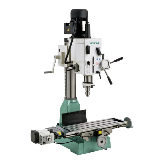
MODEL G0754
HEAVY-DUTY MILL/DRILL
w/POWER FEED
OWNER'S MANUAL
(For models manufactured since 1/13)
Copyright © ApriL, 2013 By grizzLy industriAL, inC.
WARNING: NO PORTION OF THIS MANUAL MAY bE REPRODUcED IN ANY SHAPE
OR FORM WITHOUT THE WRITTEN APPROVAL OF GRIzzLY INDUSTRIAL, INc.
#ts15626 printed in ChinA
Advertisement
Table of Contents

Related Manuals for Grizzly G0754


Summary of Contents for Grizzly G0754
- Page 1 OWNER'S MANUAL (For models manufactured since 1/13) Copyright © ApriL, 2013 By grizzLy industriAL, inC. WARNING: NO PORTION OF THIS MANUAL MAY bE REPRODUcED IN ANY SHAPE OR FORM WITHOUT THE WRITTEN APPROVAL OF GRIzzLY INDUSTRIAL, INc. #ts15626 printed in ChinA...
- Page 2 This manual provides critical safety instructions on the proper setup, operation, maintenance, and service of this machine/tool. Save this document, refer to it often, and use it to instruct other operators. Failure to read, understand and follow the instructions in this manual may result in fire or serious personal injury—including amputation, electrocution, or death.
-
Page 3: Table Of Contents
Table of contents INTRODUcTION ..........2 graduated index rings ........21 Machine description ........2 X-Axis handwheel ..........22 Contact info............ 2 y-Axis handwheel ..........22 Manual Accuracy ........... 2 X-Axis power Feed ........... 22 installing/removing tooling ......23 identification ........... 3 Machine data sheet ........ -
Page 4: Introduction
This will help us help you faster. into the machine id label (see below). this infor- mation helps us determine if updated documenta- Grizzly Technical Support tion is available for your machine. 1203 Lycoming Mall Circle Muncy, PA 17756 Phone: (570) 546-9663 Email: techsupport@grizzly.com... -
Page 5: Identification
Identification drawbar Motor Cover speed Levers depth scale & pointer Coarse downfeed Lever z-Axis Crank downfeed selector Knob Column Fine downfeed handwheel Quill Lock FWd/reV Lever Quill spindle switch & spindle table X-Axis handwheel y-Axis handwheel X-Axis power Feed To reduce your risk of serious injury, read this entire manual... -
Page 6: Machine Data Sheet
Machine Data Sheet MACHINE DATA SHEET Customer Service #: (570) 546-9663 · To Order Call: (800) 523-4777 · Fax #: (800) 438-5901 MODEL G0754 HEAVY-DUTY MILL/DRILL WITH POWER FEED Product Dimensions: Weight................................640 lbs. Width (side-to-side) x Depth (front-to-back) x Height................47 x 31 x 56 in. Footprint (Length x Width).......................... - Page 7 Main Specifications: Operation Info Spindle Travel.............................. 5 in. Max Distance Spindle to Column....................... 11 in. Max Distance Spindle to Table........................17 in. Longitudinal Table Travel (X-Axis)...................... 14-1/2 in. Cross Table Travel (Y-Axis)......................... 8 in. Vertical Head Travel (Z-Axis)......................14-1/2 in. Head Tilt (Left/Right)..........................
-
Page 8: Section 1: Safety
SEcTION 1: SAFETY For Your Own Safety, Read Instruction Manual before Operating This Machine The purpose of safety symbols is to attract your attention to possible hazardous conditions. This manual uses a series of symbols and signal words intended to convey the level of impor- tance of the safety messages. - Page 9 WEARING PROPER APPAREL. do not wear FORcING MAcHINERY. do not force machine. clothing, apparel or jewelry that can become it will do the job safer and better at the rate for entangled in moving parts. Always tie back or which it was designed. cover long hair.
-
Page 10: Additional Safety For Mill/Drills
Additional Safety for Mill/Drills UNDERSTANDING cONTROLS. Make sure you WORK HOLDING. A workpiece that moves unex- understand the use and operation of all controls pectedly during operation can result in personal before starting the mill/drill. injury or damage to tooling and the machine. Before starting the machine, be certain the workpiece is SAFETY AccESSORIES. -
Page 11: Section 2: Power Supply
SEcTION 2: POWER SUPPLY Availability circuit Requirements for 220V Before installing the machine, consider the avail- This machine is prewired to operate on a 220V power supply circuit that has a verified ground and ability and proximity of the required power supply circuit. -
Page 12: Grounding Instructions
Grounding Instructions Improper connection of the equipment-grounding wire can result in a risk of electric shock. The This machine MUST be grounded. In the event wire with green insulation (with or without yellow of certain malfunctions or breakdowns, grounding stripes) is the equipment-grounding wire. If repair reduces the risk of electric shock by providing a or replacement of the power cord or plug is nec- path of least resistance for electric current. -
Page 13: Section 3: Setup
SEcTION 3: SETUP Unpacking Inventory Your machine was carefully packaged for safe The following is a list of items shipped with your transportation. Remove the packaging materials machine. Before beginning setup, lay these items from around your machine and inspect it. If you out and inventory them. -
Page 14: Cleanup
cleanup Gasoline and petroleum products have low flash the unpainted surfaces of your machine are points and can explode coated with a heavy-duty rust preventative that or cause fire if used to prevents corrosion during shipment and storage. clean machinery. Avo i d this rust preventative works extremely well, but it u sing t h e s e p r o d u c t s will take a little time to clean. -
Page 15: Site Considerations
Site considerations Weight Load Physical Environment refer to the Machine Data Sheet for the weight the physical environment where the machine is of your machine. Make sure that the surface upon operated is important for safe operation and lon- which the machine is placed will bear the weight gevity of machine components. -
Page 16: Lifting & Placing
Lifting & Placing Mounting the machine base has holes to accommodate mounting hardware. Additionally, you may con- sider providing a hole in your workbench or HEAVY LIFT! stand for access to the underside of the machine Straining or crushing injury base. -
Page 17: Assembly
Assembly Joining Drill chuck & Arbor the mill/drill was fully assembled at the factory except for the handwheel handles. the joining of the drill chuck and arbor is intended to be semi-permanent. if you would like to use use a flat-head screwdriver to attach the a different chuck in the future, we recommend handwheels handles, as shown in Figure 8. -
Page 18: Lubricating Mill/Drill
Lubricating Mill/Drill Test Run once the assembly is complete, test run your machine to make sure it runs properly. GEARBOX MUST if, during the test run, you cannot easily locate BE FILLED WITH OIL! the source of an unusual noise or vibration, stop using the machine immediately, then review the Troubleshooting on Page 32. -
Page 19: Spindle Bearing Break-In
Spindle bearing Inspections & break-In Adjustments the following list of adjustments were performed at the factory before the machine was shipped: complete the spindle bearing break-in pro- • gib Adjustments ......Page 34 cedure to prevent rapid wear and tear of •... -
Page 20: Section 4: Operations
Read books/magazines or get formal training before beginning any proj- ects. Regardless of the content in this sec- tion, Grizzly Industrial will not be held liable for accidents caused by lack of training. -18- Model G0754 (Mfg. Since 1/13) -
Page 21: Downfeed Controls
Downfeed controls Using Fine Downfeed Tighten the downfeed selector knob to engage the fine downfeed handwheel. Identification Adjust the depth pointer with the adjustment knob as a visual downfeed guide. rotate the fine downfeed handwheel to raise and lower the spindle. Depth Stop the depth stop limits the downward movement of the cutting tool. -
Page 22: Headstock Movement
Headstock Raising/Lowering Headstock disConneCt MiLL FroM poWer! Movement Loosen the two hex nuts shown in Figure 11. use the z-axis crank shown in Figure 12 to the headstock moves in the following ways: adjust the headstock height. • rotates 360° around the column. •... -
Page 23: Tilting Headstock
Table Travel Tilting Headstock disConneCt MAChine FroM poWer! Loosen the three locking hex nuts (see the table travels in two directions, as illustrated Figures 13–14). in Figure 15: • X-axis (longitudinal) • y-axis (cross) hex nut these movements are controlled by handwheels and the X-axis power feed. -
Page 24: X-Axis Handwheel
X-Axis Handwheel Tool Needed hex Wrench 5mm ..........1 To use the X-axis handwheel: Loosen the X-axis table locks shown in Figure 17. Note: When tightened, table locks increase table rigidity. Figure 18. X-axis power feed controls. Limit stops X-Axis table Locks y-Axis table Lock... -
Page 25: Installing/Removing Tooling
Installing/Removing Installing Tooling disConneCt MAChine FroM poWer! Tooling remove the drawbar cap as shown in Figure 21. the Model g0754 includes the following spindle tools (see Figure 20): drawbar drawbar Cap A. b16 Drill chuck w/R-8 Arbor. Joined with the drill chuck. b. -
Page 26: Removing Tooling
Spindle Speed Removing Tooling Tools Needed Wrench 19mm ........... 1 Brass head or dead Blow hammer ....1 using the correct spindle speed is important for safe and satisfactory results, as well as maximiz- To remove tooling: ing tool life. disConneCt MAChine FroM poWer! to set the spindle speed for your operation, you will need to: 1) determine the best spindle speed... -
Page 27: Setting Spindle Speed
Setting Spindle Speed With the spindle completely stopped, position the spindle speed levers (see Figure 23) to set the use the chart below or the one on the headstock spindle speed. when setting the spindle speed. Note: If necessary, rotate the spindle by hand to Spindle Speed Range Lever Speed Lever mesh the gears when changing speeds. -
Page 28: Section 5: Accessories
To reduce this risk, only install accessories well as reduce chatter or slip. Buy in bulk and recommended for this machine by Grizzly. save with 5-gallon quantities. NOTICE t23962... - Page 29 Model h9599 has 320 pages. Model g5053 has 275 pages. Figure 31. Model sB1349 south Bend 16-pc. r-8 Collet set. h9599 g5053 Figure 29. great texts for mill/drills. www.grizzly.com 1-800-523-4777 order online at or call -27- Model G0754 (Mfg. Since 1/13)
-
Page 30: Section 6: Maintenance
• Worn or damaged wires. regular applications iso 68 way oil (see Page 26 • Clean debris and built up grime off of machine. for offerings from grizzly). • Any other unsafe condition. Every 8 Hours of Operation: Lubrication Check/add headstock oil (Page 29). -
Page 31: Headstock
Headstock place a 1-gallon or larger drain pan on the table under the headstock. oil type ..Model t23962 or iso 68 equivalent oil Amount ..........3 ⁄ remove the drain plug (see Figure 34) from Check/Add Frequency ... 8 hrs. of operation underneath the headstock and allow the oil to Change Frequency ........ -
Page 32: Ball Oilers
(see Page 26 for offerings from grizzly). We do not recommend using metal needle or lance tips, as they can push the ball too far into the oiler, break the spring seat, and lodge the ball in the oil galley. -
Page 33: Table Leadscrews
Table Leadscrews Quill Rack & Pinion oil type ..Model t23962 or iso 68 equivalent oil type ....nLgi#2 grease or equivalent oil Amount ..........thin Coat oil Amount ..........thin Coat Lubrication Frequency ..40 hrs. of operation Lubrication Frequency ..90 hrs. of operation Move the table as necessary to access the entire Move the quill up and down to gain full access length of the X- and y-axis leadscrews (see... -
Page 34: Section 7: Service
SEcTION 7: SERVIcE Review the troubleshooting and procedures in this section if a problem develops with your machine. If you need replacement parts or additional help with a procedure, call our Technical Support at (570) 546-9663. Note: Please gather the serial number and manufacture date of your machine before calling. Troubleshooting symptom possible Cause... - Page 35 symptom possible Cause possible solution tool slips in spindle. 1. tool is not fully drawn up into 1. tighten drawbar. spindle taper. 2. debris on tool or in spindle taper. 2. Clean collet and spindle taper. 3. taking too big of a cut. 3.
-
Page 36: Adjusting Gibs
Adjusting Gibs Adjusting Leadscrew backlash gibs are tapered lengths of metal that are sand- wiched between two moving surfaces. gibs con- Leadscrew backlash is the amount of freeplay trol the gap between these surfaces and how they movement in the leadscrew (when changing the slide past one another. -
Page 37: Section 8: Wiring
Technical source. Support at (570) 546-9663. The photos and diagrams included in this section are best viewed in color. You can view these pages in color at www.grizzly.com. -35- Model G0754 (Mfg. Since 1/13) -
Page 38: Electrical Wiring
Electrical Wiring 220V Motor Ground 220V NEMA 6-15 (As Recommended) Start Capacitor Capacitor Ground 20MFD 150MFD 450VAC 250VAC V1 U2 Spindle Switch Left Right Side Side Ground READ ELECTRICAL SAFETY -36- Model G0754 (Mfg. Since 1/13) ON PAGE 35! -
Page 39: Section 9: Parts
Please Note: We do our best to stock replacement parts whenever possible, but we cannot guarantee that all parts shown here are available for purchase. Call (800) 523-4777 or visit our online parts store at www.grizzly.com to check for availability. -
Page 40: Head Parts List
Head Parts List REF PART # DESCRIPTION REF PART # DESCRIPTION P0754001 HEADSTOCK HOUSING P0754048 GEAR 43T P0754002 HEADSTOCK TOP COVER P0754049 GEAR 16T PR38M INT RETAINING RING 62MM PK182M KEY 6 X 6 X 75 PR21M INT RETAINING RING 35MM PK36M KEY 5 X 5 X 50 P0754005... - Page 41 Head Parts List REF PART # DESCRIPTION REF PART # DESCRIPTION P0754106 INSIDE LOCK PLUNGER P0754114 SHIFT ROD P0754107 OUTSIDE LOCK PLUNGER P0754115 SHAFT SEAL P0754108 ADJUSTABLE HANDLE P0754116 SPEED SHIFT SHAFT P0754109 SPEED RANGE SHIFT SHAFT P0754117 SPEED SHIFT FORK P0754110 SPEED RANGE SHIFT ROCKER ARM P0754118...
-
Page 42: Table & Column
Table & column REF PART # DESCRIPTION REF PART # DESCRIPTION P0754201 BASE PCAP13M CAP SCREW M8-1.25 X 30 P0754202 COLUMN P0754252 SADDLE GIB P0754203 CROSS LEADSCREW BRACKET P0754254 COLUMN RACK P0754206 GIB ADJUSTMENT SCREW P0754255 COLUMN RACK LOCK RING P51103 THRUST BEARING 51103 P0754256... -
Page 43: Power Feed & Accessories
Power Feed & Accessories 301-1 301-2 301-4 301-3 301-5 REF PART # DESCRIPTION REF PART # DESCRIPTION T24824 POWER FEED ASSY ALIGN AS-235 P0754309 SPINDLE SLEEVE MT#3-MT#2 301-1 PT24824001A MOUNTING BRACKET 2-PC P0754310 DRILL CHUCK ARBOR R8-B16 301-2 PT24824002 CONTROL HANDLE P0754311 SPINDLE SLEEVE R8-MT#3 301-3 PT24824003... -
Page 44: Labels & Cosmetics
Safety labels help reduce the risk of serious injury caused by machine hazards. If any label comes off or becomes unreadable, the owner of this machine MUST replace it in the original location before resuming operations. For replacements, contact (800) 523-4777 or www.grizzly.com. -42-... -
Page 45: Warranty Card
Would you recommend Grizzly Industrial to a friend? _____ Yes _____No Would you allow us to use your name as a reference for Grizzly customers in your area? Note: We never use names more than 3 times. _____ Yes _____No 10. - Page 46 FOLD ALONG DOTTED LINE Place Stamp Here GRIZZLY INDUSTRIAL, INC. P.O. BOX 2069 BELLINGHAM, WA 98227-2069 FOLD ALONG DOTTED LINE Send a Grizzly Catalog to a friend: Name_______________________________ Street_______________________________ City______________State______Zip______ TAPE ALONG EDGES--PLEASE DO NOT STAPLE...
-
Page 47: Warranty & Returns
WARRANTY & RETURNS Grizzly Industrial, Inc. warrants every product it sells for a period of 1 year to the original purchaser from the date of purchase. This warranty does not apply to defects due directly or indirectly to misuse, abuse, negligence, accidents, repairs or alterations or lack of maintenance.