Table of Contents
Advertisement
Quick Links
For questions or help with this product contact Tech Support at (570) 546-9663 or techsupport@grizzly.com
The following change was recently made to this machine since the owner's manual was printed:
•
Removed wire between spindle direction knob and circuit board (see Figure 1), making speed range
identical in forward and reverse. Refer to updated wiring diagram on following page.
Aside from this information, all other content in the owner's manual applies and MUST be read and under-
stood for your own safety. IMPORTANT: Keep this update with the owner's manual for future reference.
For questions or help, contact our Tech Support at (570) 546-9663 or techsupport@grizzly.com.
Wire
Removed
WARNING: NO PORTION OF THIS MANUAL MAY BE REPRODUCED IN ANY SHAPE
OR FORM WITHOUT THE WRITTEN APPROVAL OF GRIZZLY INDUSTRIAL, INC.
READ THIS FIRST
P3
P2
P1
Circuit Board
JD-014 5WR02J
A
Fuse
F10AL250V
10A
A
Circuit Board
B
CESX 1101-28
IN
N
N1
G
IN
L1
L
RPM Display
ZD-SX-THL
A1
On/Off Switch
Kedu KJD-178/120V
10
12
11
9
Spindle
6
8
7
5
Speed
Knob
2
4
3
1
WX14-12
Spindle Direction Knob
Kedu EN61058
Figure 1. Location of wire removed.
COPYRIGHT © MAY, 2016 BY GRIZZLY INDUSTRIAL, INC.
#BL18227 PRINTED IN CHINA
Model G0759
***IMPORTANT UPDATE***
For Machines Mfd. Since 05/16
and Owner's Manual Revised 07/15
A+
L1
L2
Fuse
F15AL250V
15A
Gnd
Gnd
23
24
13
14
Neutral
Hot
110 VAC
5-15 Plug
Ground
Chip Guard
Spindle
Limit Switch
RPM Sensor
Motor
Brushes
110V Motor
Advertisement
Table of Contents

Related Manuals for Grizzly G0759


Summary of Contents for Grizzly G0759
- Page 1 ***IMPORTANT UPDATE*** For Machines Mfd. Since 05/16 and Owner's Manual Revised 07/15 Neutral For questions or help with this product contact Tech Support at (570) 546-9663 or techsupport@grizzly.com Circuit Board 110 VAC JD-014 5WR02J The following change was recently made to this machine since the owner's manual was printed:...
- Page 2 Spindle Limit Switch Fuse Fuse RPM Sensor F10AL250V F15AL250V Circuit Board CESX 1101-28 Motor Brushes Figure 64 110V Motor RPM Display ZD-SX-THL On/Off Switch Kedu KJD-178/120V Spindle Speed Knob WX14-12 Spindle Direction Knob Kedu EN61058 G0759 Update (Mfd. Since 5/16)
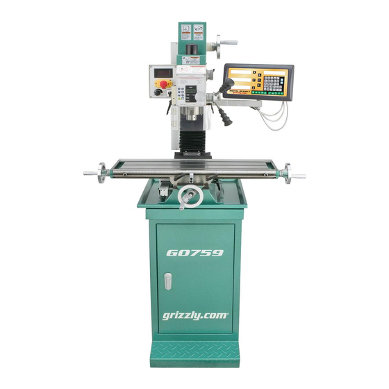
- Page 3 & DRO MANUAL INSERT The Model G0759 is the same machine as the Model G0704 except the Model G0759 has a 3-axis DRO. Besides the differences noted in this insert, all other content in the Model G0704 owner's manual applies to this machine.
- Page 4 MACHINE DATA SHEET Customer Service #: (570) 546-9663 · To Order Call: (800) 523-4777 · Fax #: (800) 438-5901 MODEL G0759 MILL/DRILL WITH STAND AND DRO Product Dimensions: Weight................................280 lbs. Width (side-to-side) x Depth (front-to-back) x Height................38 x 24 x 31 in.
- Page 5 The information contained herein is deemed accurate as of 11/29/2018 and represents our most recent product specifications. Model G0759 PAGE 2 OF 3 Due to our ongoing improvement efforts, this information may not accurately describe items previously purchased. Model G0759 (Mfd. Since 1/14)
- Page 6 Please Note: We do our best to stock replacement parts whenever possible, but we cannot guarantee that all parts shown here are available for purchase. Call (800) 523-4777 or visit our online parts store at www.grizzly.com to check for availability.
- Page 7 HANDWHEEL CURVED PLATE SPRING 412-1 P0759412-1 DRO DISPLAY P0759040 HEX NUT M8-1.25 412-2 P0759412-2 X-AXIS DRO SCALE P0759041 Z-AXIS HANDWHEEL HANDLE M6-1 X 10 412-3 P0759412-3 Y-AXIS DRO SCALE P0759042 BALL BEARING 6001ZZ 412-4 P0759412-4 Z-AXIS DRO SCALE Model G0759 (Mfd. Since 1/14)
- Page 8 CAP SCREW M4-.7 X 10 P0759094 STRAIN RELIEF M20 X 1.5 TYPE-3 P0759085 CONTROL PANEL PLATE P0759095 FWD/REV SWITCH KEDU EN61058 P0759086 CAP SCREW M4-.7 X 6 P0759096 FUSE 10A 250V FAST-ACTING, GLASS P0759087 RPM DIGITAL DISPLAY ZD-SX-THL Model G0759 (Mfd. Since 1/14)
- Page 9 Headstock 206-2 206-1 221-2 209-2 221-1 209-1 225-2 225-1 216 217 218 234-1 234-2 246-2 246-1 255-1 Model G0759 (Mfd. Since 1/14)
- Page 10 WRENCH 17 X 19MM OPEN-ENDS P0759240 CAP SCREW M4-.7 X 8 P0759408 SCREWDRIVER FLAT #2 P0759241 FINE FEED KNOB P0759409 SCREWDRIVER PHILLIPS #2 P0759242 HEADSTOCK FRONT COVER P0759410 BOTTLE FOR OIL P0759243 HANDWHEEL CURVED PLATE SPRING P0759411 TOOLBOX Model G0759 (Mfd. Since 1/14)
- Page 11 EXT RETAINING RING 12MM P0759287 CHIP GUARD POST P0759281 WAVY WASHER 20MM P0759288 CHIP GUARD P0759282 GUARD MOUNTING BLOCK P0759289 CAP SCREW M4-.7 X 18 P0759283 LIMIT SWITCH L-BRACKET, COPPER P0759297 CAP SCREW M3-.5 X 16 Model G0759 (Mfd. Since 1/14)
- Page 12 Safety labels help reduce the risk of serious injury caused by machine hazards. If any label comes off or becomes unreadable, the owner of this machine MUST replace it in the original location before resuming operations. For replacements, contact (800) 523-4777 or www.grizzly.com. -10-...
- Page 13 OWNER'S MANUAL (For models manufactured since 05/16) COPYRIGHT © FEBRUARY, 2010 BY GRIZZLY INDUSTRIAL, INC. REVISED JULY, 2018 (HE) WARNING: NO PORTION OF THIS MANUAL MAY BE REPRODUCED IN ANY SHAPE OR FORM WITHOUT THE WRITTEN APPROVAL OF GRIZZLY INDUSTRIAL, INC.
- Page 14 This manual provides critical safety instructions on the proper setup, operation, maintenance, and service of this machine/tool. Save this document, refer to it often, and use it to instruct other operators. Failure to read, understand and follow the instructions in this manual may result in fire or serious personal injury—including amputation, electrocution, or death.
-
Page 15: Table Of Contents
Table of Contents INTRODUCTION ..........2 SECTION 5: ACCESSORIES ......33 Manual Accuracy ........... 2 SECTION 6: MAINTENANCE ......36 Contact Info............ 2 Schedule ............36 Machine Description ........2 Lubrication ........... 36 Identification ........... 3 Electronic Controls Identification ....4 SECTION 7: SERVICE ........ -
Page 16: Introduction
In drilling operations, the workpiece is held sta- at www.grizzly.com. Any updates to your model tionary on the table while the cutting tool moves of machine will be reflected in these documents up-and-down with the movement of the spindle as soon as they are complete. -
Page 17: Identification
Identification Figure 1. G0704 Identification. N. Storage Access Door A. Drawbar Cap and Drawbar O. Cross (Y-Axis) Handwheel B. Vertical (Z-Axis) Handwheel P. Longitudinal Scalev C. Speed Range Selector Knob Q. Drill Chuck D. Vertical Travel Lock R. Headstock Tilt Scale E. -
Page 18: Electronic Controls Identification
Electronic Controls Identification Figure 2. G0704 electronic controls identification. G. IN/MM Unit Selection Button A. Spindle RPM Readout H. Spindle Depth Display B. Spindle Digital Readout Power Button Spindle Direction Selection Knob C. Digital Readout ZERO Button Variable Spindle Speed Knob D. -
Page 19: Machine Data Sheet
MACHINE DATA SHEET Customer Service #: (570) 546-9663 · To Order Call: (800) 523-4777 · Fax #: (800) 438-5901 MODEL G0704 MILL/DRILL WITH STAND Product Dimensions: Weight................................265 lbs. Width (side-to-side) x Depth (front-to-back) x Height................38 x 24 x 31 in. Footprint (Length x Width)....................... - Page 20 Main Specifications: Operation Info Spindle Travel.............................. 2 in. Max Distance Spindle to Column......................7-1/2 in. Max Distance Spindle to Table........................13 in. Longitudinal Table Travel (X-Axis)...................... 18-7/8 in. Cross Table Travel (Y-Axis)........................6-7/8 in. Vertical Head Travel (Z-Axis)........................11 in. Head Tilt (Left/Right)..........................
- Page 21 Accessories Included: Drill chuck 3–16mm with B16 taper Drill chuck arbor B16 x R8 Two T-bolts Two open-ended combo wrenches Chuck key Oil bottle Extra fuse Hex wrenches Standard and Phillips screwdrivers Tool box The information contained herein is deemed accurate as of 4/25/2019 and represents our most recent product specifications. Model G0704 PAGE 3 OF 3 Due to our ongoing improvement efforts, this information may not accurately describe items previously purchased.
-
Page 22: Section 1: Safety
SECTION 1: SAFETY For Your Own Safety, Read Instruction Manual Before Operating This Machine The purpose of safety symbols is to attract your attention to possible hazardous conditions. This manual uses a series of symbols and signal words intended to convey the level of impor- tance of the safety messages. - Page 23 INTENdEd usAGE. Only use machine for its machine in good working condition. A machine intendedpurposeandnevermakemodifications that is improperly maintained could malfunction, not approved by Grizzly. Modifying machine or leadingtoseriouspersonalinjuryordeath. using it differently than intended may result in ChECK dAMAGEd PARTs. Regularly inspect...
-
Page 24: Additional Safety For Mill/Drills
Additional Safety for Mill/Drills You can be seriously injured or killed by getting clothing, jewelry, or long hair entangled with rotating cutter/spindle. You can be severely cut or have fingers amputated from contact with rotating cutters. You can be blinded or struck by broken cutting tools, metal chips, workpieces, or adjustment tools thrown from the rotating spindle with great force. -
Page 25: Section 2: Power Supply
SECTION 2: POWER SUPPLY Availability Circuit Requirements Before installing the machine, consider the avail- This machine is prewired to operate on a 110V ability and proximity of the required power supply power supply circuit that has a verified ground and circuit. - Page 26 Grounding & Plug Requirements Improper connection of the equipment-grounding wire can result in a risk of electric shock. The This machine MUST be grounded. In the event wire with green insulation (with or without yellow of certain malfunctions or breakdowns, grounding stripes) is the equipment-grounding wire.
-
Page 27: Section 3: Setup
If you ects. Regardless of the content in this sec- discover any damage, please call us immediately tion, Grizzly Industrial will not be held liable at (570) 546-9663 for advice. for accidents caused by lack of training. -
Page 28: Inventory
Inventory The following is a list of items shipped with your machine. Before beginning setup, lay these items out and inventory them. If any non-proprietary parts are missing (e.g. a nut or a washer), we will gladly replace them; or for the sake of expediency, replacements can be obtained at your local hardware store. -
Page 29: Cleanup
Cleanup Gasoline or products with low flash points can The unpainted surfaces of your machine are explode or cause fire if coated with a heavy-duty rust preventative that used to clean machin- prevents corrosion during shipment and storage. ery. Avoid cleaning with This rust preventative works extremely well, but it these products. -
Page 30: Site Considerations
Site Considerations Weight Load Physical Environment Refer to the Machine Data Sheet for the weight The physical environment where the machine is of your machine. Make sure that the surface upon operated is important for safe operation and lon- which the machine is placed will bear the weight gevity of machine components. -
Page 31: Moving & Placing Machine
Moving & Placing Unbolt the machine from the pallet, then with an assistant steadying the machine to pre- Machine vent it from swinging, lift it slightly off of the pallet. Use the cross handwheel to move the table forward or backward as necessary to balance the machine so it hangs as close to level as possible. -
Page 32: Mounting To Shop Floor
Mounting to Shop Using Machine Mounts Using machine mounts, shown in Figure 11, gives Floor the advantage of fast leveling and vibration reduc- tion. The large size of the foot pads distributes the weight of the machine to reduce strain on the floor. -
Page 33: Assembly
Assembly Drill Chuck Arbor Assembly of the Model G0704 consists of attach- Your machine includes an B-16 drill chuck arbor ing the four handwheel handles to the machine. and drill chuck. Before use, the drill chuck must be installed onto the arbor. The This drill chuck To assemble your machine: installation is intended to be semi-permanent. -
Page 34: Test Run
Test Run Spindle RPM Readout Once assembly is complete, test run the machine Emergency to ensure it is properly connected to power and Stop Button safety components are functioning correctly. Spindle If you find an unusual problem during the test run, Direction immediately stop the machine, disconnect it from Knob... -
Page 35: Spindle Break-In
Spindle Break-In To perform spindle break-in process: Successfully complete Test Run procedure beginning on Page 20. The spindle break-in procedure distributes lubri- cation throughout the bearings to reduce the risk Open the Emergency Stop button cover and of early bearing failure if there are any "dry" spots press the green button to start the spindle. -
Page 36: Section 4: Operations
Regardless of the content in this section, 11. Turns the spindle direction knob to the "0" Grizzly Industrial will not be held liable for position to stop the spindle. accidents caused by lack of training. -
Page 37: Basic Controls
Basic Controls Vertical Handwheel Speed Range Selector Knob To reduce your risk of serious injury, read this Vertical Fine entire manual BEFORE Travel Feed using machine. Locks Knob Loose hair, clothing, or jewelry could get caught Fine in machinery and cause Feed serious personal injury. - Page 38 Cross Handwheel: Moves the table forward and Power Button: Turns display ON/OFF. backward (Y-Axis). ZERO Button: Resets the display to 0.000". Hold Longitudinal Handwheels: Move the table from down until "S" flashes on the readout to enable side to side (X-Axis). buttons.
-
Page 39: Digital Readout Unit
Digital Readout Unit To use the digital readout: Press the power button (see Figure 21). A reading should appear on the display. The digital readout unit gives a precise reading of the vertical positioning of the quill. It can be Press the IN/MM button to select whether zeroed at any position and manually increased or units will be displayed in inches or millime-... -
Page 40: Calculating Spindle Speed
Calculating Spindle Cutting Speeds for High Speed Steel (HSS) Cutting Tools Speed Workpiece Material Cutting Speed (sfm) Aluminum & Alloys Brass & Bronze Closely follow the proper spindle speed and Copper proper feed rate to produce good results, reduce Cast Iron, soft undue strain on all moving parts and increase Cast Iron, hard operator safety. -
Page 41: Spindle Speed And Direction
Spindle Speed and Note: It may be necessary to rotate the spindle by hand to get the gears to mesh Direction properly. Make sure the work area is clear and that all safety precautions are taken. Setting the speed on the Model G0704 is a two part process. -
Page 42: Spindle Height Controls
Spindle Height Changing Spindle Position Using Fine Feed Knob Controls Unlock the quill lock lever and tighten the fine feed lock knob. The spindle height is controlled by the quill feed Rotate the fine feed knob to lower or raise lever and the fine feed knob. -
Page 43: Drill Chuck
Drill Chuck NOTICE The Model G0704 drawbar will extract the arbor from the spindle. Once the arbor or To install the drill chuck and arbor: collet has broken free from the spindle taper, be sure to properly support it while DISCONNECT MILL/DRILL FROM POWER! continuing to loosen the drawbar. -
Page 44: Loading Tooling
Loading Tooling To remove the collet: DISCONNECT MILL/DRILL FROM POWER! Your Model G0704 features an R-8 spindle taper, Remove the drawbar cap. which gives the freedom to use standard R-8 cutting tools and collets. These optional collets Lock the quill in place with the quill lock come in many sizes, typically ranging from ⁄... -
Page 45: Headstock Travel (Z-Axis And Rotation)
Headstock Travel To tilt the headstock to the left or right: (Z-Axis and Rotation) DISCONNECT MILL/DRILL FROM POWER. Headstock height is adjustable in the vertical During the following steps, be aware that the Z-axis to accept large workpieces. For unique headstock is top-heavy and will swing if it is milling operations, the headstock can be tilted not well supported once the center bolt and... - Page 46 Table Travel X-Axis Handwheels The mill/drill table can be moved in the longitudi- nal (X-axis) and cross (Y-axis) directions. Longitudinal Feed The X-axis is moved by the handwheels shown in Figure 30 at the end of the table. These handwheels will move the table in both directions Y-Axis Handwheel side-to-side.
-
Page 47: Section 5: Accessories
To reduce this risk, only install accessories recommended for this machine by Grizzly. NOTICE Refer to our website or latest catalog for additional recommended accessories. H8179—Horizontal Milling Table Take advantage of the G0704 mill/drill 90°... - Page 48 600 lb. load capacity in one small package! T20451 H7194 Figure 39. Assortment of basic eye protection. Figure 37. Model D2260A Mini Shop Fox ® Mobile Base. www.grizzly.com 1-800-523-4777 order online at or call -34- Model G0704 (Mfd. Since 05/16)
- Page 49 Table size: 5" x 7". SB1365—South Bend Way Oil-ISO 68, 12 oz. T23964—Moly-D Multi-purpose NLGI#2 Grease Figure 43. Recommended products for machine lubrication. Figure 41. Model G5758 Tilt Table. www.grizzly.com 1-800-523-4777 order online at or call -35- Model G0704 (Mfd. Since 05/16)
-
Page 50: Section 6: Maintenance
SECTION 6: MAINTENANCE Always disconnect power to the machine before performing maintenance. Failure to do this may result in serious person- al injury. Schedule For optimum performance from your machine, Figure 44. Vertical way lube location (both follow this maintenance schedule and refer to any sides). - Page 51 Every six months, or more frequently under heavy Lift or remove the rubber way cover, then use, we recommend that you clean and lubricate use mineral spirits and a brush to clean as the leadscrews and vertical handwheel gears with much of the existing grease and debris as a light machine oil and multi-purpose grease.
- Page 52 To lubricate the vertical leadscrew bushing Remove the acorn nut and flat washer that and ring & pinion gears: secure the vertical handwheel, then remove the handwheel (Figure 52). DISCONNECT MILL/DRILL FROM POWER! Remove the bushing cap by unthreading the four cap screws that secure it (Figure 50).
-
Page 53: Section 7: Service
Troubleshooting SECTION 7: SERVICE Review the troubleshooting and procedures in this section if a problem develops with your machine. If you need replacement parts or additional help with a procedure, call our Technical Support at (570) 546-9663. Note: Please gather the serial number and manufacture date of your machine before calling. Troubleshooting Symptom Possible Cause... - Page 54 Symptom Possible Cause Possible Solution Tool slips in collet. 1. Collet is not fully drawn up into 1. Tighten drawbar. spindle taper. 2. Wrong size collet. 2. Measure tool shank diameter and match with appropriate diameter collet. 3. Debris on collet or in spindle taper. 3.
-
Page 55: Gibs
Gibs To adjust the headstock gibs: DISCONNECT MILL/DRILL FROM POWER! Gibs are wedge-shaped pieces of metal that Remove the two screws that secure the top fill the gap between the sliding surfaces of the end of the way cover, pull it down to expose machine. -
Page 56: Leadscrew Backlash
Leadscrew Backlash To adjust the Y-axis leadscrew nut: Locate the leadscrew nut underneath the table through the hole in the base under the When you turn the handwheels to adjust the posi- rubber way cover. tion of the table, you will notice slight play (back- lash) in the handwheel before the table begins to Tighten the adjustment screws on the move. -
Page 57: Motor Service
Motor Service Unscrew one of the brush caps to expose the brush assembly (Figure 59). The bearings inside the motor are shielded and lubricated for the life of the bearing and require no routine maintenance. This motor is equipped with long life carbon brushes. -
Page 58: Section 8: Wiring
Technical source. Support at (570) 546-9663. The photos and diagrams included in this section are best viewed in color. You can view these pages in color at www.grizzly.com. -44- Model G0704 (Mfd. Since 05/16) -
Page 59: Wiring Diagram
Wiring Diagram Neutral See Figure 61 Circuit Board 110 VAC JD-014 5WR02J 5-15 Plug Ground See Figure 62 Chip Guard Spindle Limit Switch Fuse Fuse RPM Sensor F10AL250V F15AL250V Circuit Board CESX 1101-28 Motor Brushes Figure 64 110V Motor RPM Display ZD-SX-THL On/Off Switch Kedu KJD-178/120V... -
Page 60: Electrical Components
Electrical Components Figure 61. Rear panel. Figure 63. Control panel wiring. Figure 62. Chip guard limit switch. Figure 64. Side panel. READ ELECTRICAL SAFETY -46- Model G0704 (Mfd. Since 05/16) ON PAGE 44! -
Page 61: Section 9: Parts
SECTION 9: PARTS Column Breakdown 31-1 34 35 36 37 39 14 15 100-1 100-2 100-3 -47- Model G0704 (Mfd. Since 05/16) -
Page 62: Column Parts List
Column Parts List REF PART # DESCRIPTION PART # DESCRIPTION P0704001 Z-AXIS SLIDE P0704041 Z-AXIS HANDWHEEL HANDLE M6-1 X 10 P0704002 SET SCREW M6-1 X 16 P0704042 BALL BEARING 6001ZZ P0704003 FLAT WASHER 8MM P0704043 Z-AXIS HANDWHEEL SHAFT P0704004 LOCK WASHER 8MM P0704044 KEY 4 X 4 X 12 P0704005... -
Page 63: Electrical Box Breakdown & Parts List
Electrical Box Breakdown & Parts List 92V2 79-1 80-1 REF PART # DESCRIPTION REF PART # DESCRIPTION P0704078 CIRCUIT BOARD P0704087 RPM DIGITIAL DISPLAY ZD-SX-THL P0704079 SPINDLE SPEED KNOB WX14-12 P0704088 ELECTRICAL BOX 79-1 P0704079-1 SPINDLE SPEED POTENTIOMETER P0704089 CAP SCREW M5-.8 X 8 P0704080 CAP SCREW M3-.5 X 16 P0704090... -
Page 64: Headstock Breakdown
Headstock Breakdown 206-2 220V2 206-1 221-2V2 209-2 221-1V2 209-1 221V2 225-2 225-1 216 217 218 234-1 234-2 238-1 272 271 238-2 246-2 246-1 246V2 255-1 -50- Model G0704 (Mfd. Since 05/16) -
Page 65: Headstock Parts List
Headstock Parts List PART # DESCRIPTION PART # DESCRIPTION P0704201 QUILL RETAINING CLIP 238-1 P0704238-1 ROUND INSPECTION COVER P0704202 BUSHING 238-2 P0704238-2 CAP SCREW M4-.7 X 8 P0704203 COMPRESSION SPRING P0704239 COVER PLATE P0704204 EXT RETAINING RING 45MM P0704240 CAP SCREW M4-.7 X 8 P0704205 BALL BEARING 6209ZZ P0704241... -
Page 66: Chip Guard Breakdown & Parts List
Chip Guard Breakdown & Parts List REF PART # DESCRIPTION REF PART # DESCRIPTION P0704277 FLAT WASHER 3MM P0704284 GUARD LIMIT SWITCH P0704278 HEX NUT M3-.5 P0704285 PROTECTIVE PAPER P0704279 CAP SCREW M4-.7 X 20 P0704286 SET SCREW M5-.8 X 10 P0704280 EXT RETAINING RING 12MM P0704287... -
Page 67: Labels Breakdown & Parts List
MUST maintain the original location and readability of the labels on the machine. If any label is removed or becomes unreadable, REPLACE that label before using the machine again. Contact Grizzly at (800) 523-4777 or www.grizzly.com to order new labels. -53-... - Page 68 NOTES -54- Model G0704 (Mfd. Since 05/16)
- Page 69 Would you recommend Grizzly Industrial to a friend? _____ Yes _____No Would you allow us to use your name as a reference for Grizzly customers in your area? Note: We never use names more than 3 times. _____ Yes _____No 10.
- Page 70 FOLD ALONG DOTTED LINE Place Stamp Here GRIZZLY INDUSTRIAL, INC. P.O. BOX 2069 BELLINGHAM, WA 98227-2069 FOLD ALONG DOTTED LINE Send a Grizzly Catalog to a friend: Name_______________________________ Street_______________________________ City______________State______Zip______ TAPE ALONG EDGES--PLEASE DO NOT STAPLE...
-
Page 71: Warranty And Returns
WARRANTY AND RETURNS Grizzly Industrial, Inc. warrants every product it sells for a period of 1 year to the original purchaser from the date of purchase. This warranty does not apply to defects due directly or indirectly to misuse, abuse, negligence, accidents, repairs or alterations or lack of maintenance.