Table of Contents
Advertisement
Quick Links
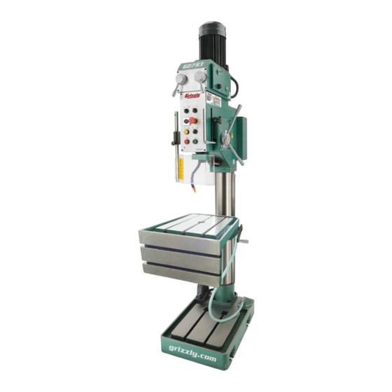
MODEL G0793
HEAVY-DUTY DRILL PRESS
w/AUTO-FEED & L-TABLE
OWNER'S MANUAL
(For models manufactured since 02/15)
COPYRIGHT © MAY, 2015 BY GRIZZLY INDUSTRIAL, INC. REVISED FEBRUARY, 2019 (MN)
WARNING: NO PORTION OF THIS MANUAL MAY BE REPRODUCED IN ANY SHAPE
OR FORM WITHOUT THE WRITTEN APPROVAL OF GRIZZLY INDUSTRIAL, INC.
#BB17384 PRINTED IN CHINA
V1.02.19
Advertisement
Table of Contents

Related Manuals for Grizzly G0793


Summary of Contents for Grizzly G0793
- Page 1 OWNER'S MANUAL (For models manufactured since 02/15) COPYRIGHT © MAY, 2015 BY GRIZZLY INDUSTRIAL, INC. REVISED FEBRUARY, 2019 (MN) WARNING: NO PORTION OF THIS MANUAL MAY BE REPRODUCED IN ANY SHAPE OR FORM WITHOUT THE WRITTEN APPROVAL OF GRIZZLY INDUSTRIAL, INC.
- Page 2 This manual provides critical safety instructions on the proper setup, operation, maintenance, and service of this machine/tool. Save this document, refer to it often, and use it to instruct other operators. Failure to read, understand and follow the instructions in this manual may result in fire or serious personal injury—including amputation, electrocution, or death.
-
Page 3: Table Of Contents
Table of Contents INTRODUCTION ..........2 SECTION 5: ACCESSORIES ......30 Contact Info............ 2 SECTION 6: MAINTENANCE ......32 Manual Accuracy ........... 2 Schedule ............32 Identification ........... 3 Cleaning and Protecting ......32 Controls & Components ......... 4 Lubrication ........... 33 Machine Data Sheet ........ -
Page 4: Introduction
ID label (see below). This information is required for us to provide proper tech support, and it helps us determine if updated documenta- tion is available for your machine. Manufacture Date Serial Number Model G0793 (Mfd. Since 02/15) -
Page 5: Identification
M. Coarse Downfeed Handles N. Table Lock Handles Chip Guard G. Coolant Pump O. Table Height Adjustment Crank H. Automatic Drift Knob To reduce your risk of serious injury, read this entire manual BEFORE using machine. Model G0793 (Mfd. Since 02/15) -
Page 6: Controls & Components
Understanding these items and how they work will help you understand the rest of the manual and stay safe when operating this machine. Figure 1. G0793 Headstock Controls and Components. A. Spindle Stop Button: Stops spindle rotation. -
Page 7: Machine Data Sheet
Machine Data Sheet MACHINE DATA SHEET Customer Service #: (570) 546-9663 · To Order Call: (800) 523-4777 · Fax #: (800) 438-5901 MODEL G0793 HEAVY‐DUTY DRILL PRESS WITH AUTO‐ FEED, TAPPING AND L‐TABLE Product Dimensions: Weight................................1026 lbs. Width (side-to-side) x Depth (front-to-back) x Height..............22 x 37 x 89-1/2 in. - Page 8 The information contained herein is deemed accurate as of 1/31/2019 and represents our most recent product specifications. Model G0793 PAGE 2 OF 2 Due to our ongoing improvement efforts, this information may not accurately describe items previously purchased. Model G0793 (Mfd. Since 02/15)
-
Page 9: Section 1: Safety
Never operate under the influence of drugs or injury or blindness from flying particles. Everyday alcohol, when tired, or when distracted. eyeglasses are NOT approved safety glasses. Model G0793 (Mfd. Since 02/15) - Page 10 Make sure they are properly installed, you experience difficulties performing the intend- undamaged, and working correctly BEFORE ed operation, stop using the machine! Contact our operating machine. Technical Support at (570) 546-9663. Model G0793 (Mfd. Since 02/15)
-
Page 11: Additional Safety For Drill Presses
Failure to do so could result in serious per- operator injury. If normal safety precautions sonal injury, damage to equipment, or poor are overlooked or ignored, serious personal work results. injury may occur. Model G0793 (Mfd. Since 02/15) -
Page 12: Section 2: Power Supply
To reduce the risk of these hazards, avoid over- loading the machine during operation and make sure it is connected to a power supply circuit that meets the specified circuit requirements. -10- Model G0793 (Mfd. Since 02/15) - Page 13 -11- Model G0793 (Mfd. Since 02/15)
-
Page 14: Section 3: Setup
Grizzly or the shipping agent. You MUST have the original pack- Inventory (Figure 3): aging to file a freight claim. - Page 15 Repeat Steps 2–3 as necessary until clean, then coat all unpainted surfaces with a quality metal protectant to prevent rust. -13- Model G0793 (Mfd. Since 02/15)
-
Page 16: Site Considerations
Only install in an Shadows, glare, or strobe effects that may distract access restricted location. or impede the operator must be eliminated. 37 " 30" minimum for 22" maintenance Figure 5. Minimum working clearances. -14- Model G0793 (Mfd. Since 02/15) -
Page 17: Lifting & Placing
With another person to help to steady machine, lift it just enough to clear pallet and any floor obstacles, then place it in its final Drilled Hole position. Figure 7. Popular method for anchoring machinery to a concrete floor. -15- Model G0793 (Mfd. Since 02/15) -
Page 18: Arbor/Chuck Assembly
Figure 8. Installing arbor into chuck. Attempt to separate drill chuck and arbor by hand —if they separate, repeat Steps 3–4. -16- Model G0793 (Mfd. Since 02/15) -
Page 19: Power Connection
Install NEMA 15-15 plug on other end of Incoming Power power cord per plug manufacturer's instruc- Strain Relief tions. Re-install main electrical panel cover. Figure 9. Electrical box with panel cover removed. -17- Model G0793 (Mfd. Since 02/15) -
Page 20: Test Run
L1 setting on spindle speed/direction switch. To test run machine: Make sure all tools and objects used during setup are cleared away from machine. Make sure machine is properly lubricated (see Page 33). -18- Model G0793 (Mfd. Since 02/15) - Page 21 Twist EMERGENCY STOP to reset, and press Spindle Stop Button. Open chip guard Congratulations! The test run is complete. Perform to activate safety switch, which should pre- the following Spindle Break-In procedure. vent the spindle from starting. -19- Model G0793 (Mfd. Since 02/15)
-
Page 22: Spindle Break-In
(refer to in that section. Lubrication on Page 33). -20- Model G0793 (Mfd. Since 02/15) -
Page 23: Section 4: Operations
ON. ects. Regardless of the content in this sec- tion, Grizzly Industrial will not be held liable Selects spindle RPM and direction with spin- for accidents caused by lack of training. -
Page 24: Installing/Removing Tooling
Use rubber or wooden mallet to seat tooling into spindle by firmly tapping from bottom. The Model G0793 includes the following spindle tools (see Figure 15): Note: If installing a drill chuck, make sure to retract jaws to prevent damage to chuck. -
Page 25: Depth Stop
18). rests on downfeed engagement lever, then tighten depth stop knob (see Figure 20). Depth Stop Knob Downfeed Engagement Lever Figure 18. Using drift key to remove arbor. Figure 20. Setting depth stop knob. -23- Model G0793 (Mfd. Since 02/15) -
Page 26: Positioning Table
Tighten lock handles. the internet. These sources will help you take into account the applicable variables in order to deter- mine the best spindle speed for the operation. -24- Model G0793 (Mfd. Since 02/15) - Page 27 130 RPM 150 RPM Figure 23. Spindle speed controls. 180 RPM 215 RPM 260 RPM 300 RPM 310 RPM 415 RPM 440 RPM 600 RPM 625 RPM 830 RPM 870 RPM 1220 RPM 1740 RPM -25- Model G0793 (Mfd. Since 02/15)
-
Page 28: Calculating Spindle Speed For Drilling
Always clamp the Often, when drilling materials other than wood, workpiece to the table to prevent injuries. some type of lubrication is necessary. Figure 24. Drilling speed chart. -26- Model G0793 (Mfd. Since 02/15) -
Page 29: Drilling Mode
Refer to Controls & Components on Page 4 to understand control functions. Ensure EMERGENCY STOP button is not pushed in. Master Power Press Spindle Start button and begin drilling Switch operation. Drilling/Tapping Switch Spindle Start Button Figure 25. Controls for drilling. -27- Model G0793 (Mfd. Since 02/15) -
Page 30: Auto-Feed
0.2 = 0.20mm of downfeed/rotation. Downfeed • 0.1 = 0.10mm of downfeed/rotation. Engagement • 0.0 disengages downfeed mechanism. Lever Figure 27. Location of downfeed engagement lever. Test on piece of scrap metal to verify repeatability. -28- Model G0793 (Mfd. Since 02/15) -
Page 31: Tapping Mode
11. Press Spindle Reverse button when spindle depth stop contacts downfeed engagement lever, and remove tap from workpiece. Figure 28. Location of coolant ball valve for regulating coolant flow. -29- Model G0793 (Mfd. Since 02/15) -
Page 32: Section 5: Accessories
Made for ⁄ " T-slots. To reduce this risk, only install accessories recommended for this machine by Grizzly. NOTICE Refer to our website or latest catalog for additional recommended accessories. G3658—TiN-Coated 115-Pc. Drill Bit Set Titanium nitride-coated bits last up to six times as Figure 31. - Page 33 Figure 36. Prescision Milling Vise. Figure 34. T23964 Armor Plate with Moly-D Multi-Purpose Grease. www.grizzly.com 1-800-523-4777 order online at or call -31- Model G0793 (Mfd. Since 02/15)
-
Page 34: Section 6: Maintenance
Gun Treatment, SLIPIT , or Boeshield T-9 (see ® ® starting the machine again. Figure 37 and the Grizzly catalog or website). • Clean debris and built up grime off of machine. • Any other unsafe condition. Every 8 Hours: •... -
Page 35: Lubrication
Headstock oil must be changed on an annual basis to ensure proper lubricity of oil. Tools Needed Open End Wrench 6mm ........1 Open End Wrench 8mm ........1 Drain Pan (2-Gallon or Larger) ......1 -33- Model G0793 (Mfd. Since 02/15) - Page 36 Replace and tighten drain plug. Fill headstock with oil to red mark on sight glass (see Figure 40). Do not fill gearbox with oil above red mark. This could damage the machine and create an overflow of oil. -34- Model G0793 (Mfd. Since 02/15)
- Page 37 Note: To help prevent rust, re-apply ISO 32 oil to Ball Oilers the column smooth surfaces that were removed during the cleaning process. Figure 41. Table support bracket ball oiler locations. Ball Oilers Figure 42. Headstock ball oiler locations -35- Model G0793 (Mfd. Since 02/15)
-
Page 38: Adding/Changing Coolant
Refill reservoir with fresh coolant. Replace reservoir lid and re-tighten cap screws. Tip: Place a couple of rare earth magnets in coolant reservoir under drain to attract small metallic pieces and prevent them from cycling through pump. -36- Model G0793 (Mfd. Since 02/15) -
Page 39: Section 7: Service
3. Trace and test wiring. Fix any errors. Tapping mode does 1. Machine is not in "Tapping Mode." 1. Rotate switch to "Tapping Mode." not work. 2. Shorted/disconnected wiring. 2. Inspect circuit boards, wiring connections. Replace/ repair as necessary. -37- Model G0793 (Mfd. Since 02/15) - Page 40 5. Adjust pilot hole size accordingly. Oil not flowing in oil- 1. Headstock oil low/out. 1. Replace headstock oil (Page 33). flow sight glass 2. Headstock oil pump at fault. 2. Replace headstock oil pump. -38- Model G0793 (Mfd. Since 02/15)
-
Page 41: Replacing Lamp Bulb
Insert new bulb and replace metal housing and work lamp cover. Figure 46. Torque limiter and set screw. Turn set screw less than a quarter of a turn. One small adjustment should compensate for any wear on limiter disc. -39- Model G0793 (Mfd. Since 02/15) -
Page 42: Section 8: Wiring
Technical Support at (570) 546-9663. The photos and diagrams included in this section are best viewed in color. You can view these pages in color at www.grizzly.com. -40- Model G0793 (Mfd. Since 02/15) -
Page 43: Wiring Overview
Control Panel Page 44 Master Power Switch Page 42 Elevation Limit Switches Electrical Page 42 Panel Page 42 Chip Guard Limit Switch Page 42 Coolant Pump Page 46 READ ELECTRICAL SAFETY -41- Model G0793 (Mfd. Since 02/15) ON PAGE 40! -
Page 44: Electrical Panel Wiring
Switch Control Panel Switch Direction Switch Coolant Pump Work Lamp Power Connection Page 47 Page 47 Page 47 Page 47 Page 47 Page 49 Page 44 Page 44 READ ELECTRICAL SAFETY -42- Model G0793 (Mfd. Since 02/15) ON PAGE 40! -
Page 45: Electrical Panel Photo
Electrical Panel Photo Figure 47. Electrical panel wiring. READ ELECTRICAL SAFETY -43- Model G0793 (Mfd. Since 02/15) ON PAGE 40! -
Page 46: Control Panel Wiring
Limit Switch LXW5-A11N CP1-10R-01 Spindle Spindle MCB-01 MCB-01 Chip Guard Start Button Stop Button Limit Switch Juche Control Panel Ground LXW/6-16 Lt/Bl (Viewed from Headstock Rear) (Viewed from Front) READ ELECTRICAL SAFETY -44- Model G0793 (Mfd. Since 02/15) ON PAGE 40! -
Page 47: Control Panel Photo
Control Panel Photo Figure 48. Control panel wiring. READ ELECTRICAL SAFETY -45- Model G0793 (Mfd. Since 02/15) ON PAGE 40! -
Page 48: Spindle Motor Wiring
To Control Panel Page 44 Ground Figure 49. Main motor wiring. Coolant Pump Wiring LAST DITCH OPTION Ground Figure 50. Coolant pump wiring. To Electrical Panel Page 42 READ ELECTRICAL SAFETY -46- Model G0793 (Mfd. Since 02/15) ON PAGE 40! -
Page 49: Section 9: Parts
Please Note: We do our best to stock replacement parts whenever possible, but we cannot guarantee that all parts shown here are available for purchase. Call (800) 523-4777 or visit our online parts store at www.grizzly.com to check for availability. -
Page 50: Gearbox
Gearbox 102-1 102-3 103 104 102-2 102-4 102-5 135 136 BUY PARTS ONLINE AT GRIZZLY.COM! -48- Model G0793 (Mfd. Since 02/15) Scan QR code to visit our Parts Store. - Page 51 O-RING 61.5 X 3.55 P0793185 KEY 6 X 4 X 28 P0793139 OIL SEAL 40 X 55 X 08MM P0793186 SHAFT BUY PARTS ONLINE AT GRIZZLY.COM! -49- Model G0793 (Mfd. Since 02/15) Scan QR code to visit our Parts Store.
-
Page 52: Downfeed Gearbox
P0793232 CAP SCREW M8-1.25 X 40 P0793212 BALL BEARING 6007-OPEN P0793233 SHAFT COVER P0793213 PLUG P0793234 PHLP HD SCR M6-1 X 12 P0793214 STEEL BALL 8MM BUY PARTS ONLINE AT GRIZZLY.COM! -50- Model G0793 (Mfd. Since 02/15) Scan QR code to visit our Parts Store. -
Page 53: Headstock
Headstock 316 317 320 321 324 325 327 328 341 342 BUY PARTS ONLINE AT GRIZZLY.COM! -51- Model G0793 (Mfd. Since 02/15) Scan QR code to visit our Parts Store. - Page 54 P0793338 ROLL PIN 3 X 25 P0793380 PLUNGER P0793339 QUILL COLLAR P0793381 SET SCREW M8-1.25 X 8 P0793340 QUILL COLLAR SHAFT BUY PARTS ONLINE AT GRIZZLY.COM! -52- Model G0793 (Mfd. Since 02/15) Scan QR code to visit our Parts Store.
-
Page 55: Electrical
ROTARY SWITCH CANSEN LW26GS-20 4P P0793419 HALOGEN WORK LAMP 24V 25W P0793410 SELECTOR SWITCH ABB C2SS2-10B-01 419-1 P0793419-1 HALOGEN BULB 50W 24V BI-PIN BUY PARTS ONLINE AT GRIZZLY.COM! -53- Model G0793 (Mfd. Since 02/15) Scan QR code to visit our Parts Store. -
Page 56: Labels & Cosmetics
Max. Distance Spindle to Table: 30-3/4" (12/05/14) • Labels must be made of WITHOUT WRITTEN APPROVAL! Grizzly will not accept labels changed without approval. 5. Avoid entanglement with spindle—tie back long hair, roll up long w/AUTO DOWNFEED & TAPPING WARNING! - Page 57 Would you recommend Grizzly Industrial to a friend? _____ Yes _____No Would you allow us to use your name as a reference for Grizzly customers in your area? Note: We never use names more than 3 times. _____ Yes _____No 10.
- Page 58 FOLD ALONG DOTTED LINE Place Stamp Here GRIZZLY INDUSTRIAL, INC. P.O. BOX 2069 BELLINGHAM, WA 98227-2069 FOLD ALONG DOTTED LINE Send a Grizzly Catalog to a friend: Name_______________________________ Street_______________________________ City______________State______Zip______ TAPE ALONG EDGES--PLEASE DO NOT STAPLE...
-
Page 59: Warranty & Returns
WARRANTY & RETURNS Grizzly Industrial, Inc. warrants every product it sells for a period of 1 year to the original purchaser from the date of purchase. This warranty does not apply to defects due directly or indirectly to misuse, abuse, negligence, accidents, repairs or alterations or lack of maintenance.