Garmin G500 Pilot's Manual
Avionics display system
Hide thumbs
Also See for G500:
- Pilot's manual (410 pages) ,
- Instructions manual (334 pages) ,
- Reference manual (104 pages)
Table of Contents
Advertisement
Quick Links
Advertisement
Table of Contents

Related Manuals for Garmin G500


Summary of Contents for Garmin G500
- Page 1 G500 Pilot’s Guide...
- Page 2 Garmin Ltd. or its subsidiaries. Garmin ® ® ® SVT™ is a trademark of Garmin Ltd. or its subsidiaries. These trademarks may not be used without the express permission of Garmin. NavData is a registered trademark of Jeppesen, Inc.; SkyWatch is a registered trademark of L-3 ®...
-
Page 3: Limited Warranty
Garmin retains the exclusive right to repair or replace the unit or software, or to offer a full refund of the purchase price, at its sole discretion. SUCH REMEDY SHALL BE YOUR SOLE AND EXCLUSIVE REMEDY FOR ANY BREACH OF WARRANTY. - Page 4 Although unlikely, it may be possible for erroneous operation to occur without a fault indication shown by the G500. It is thus the responsibility of the pilot to detect such an occurrence by means of cross-checking with all redundant or correlated information available in the cockpit.
- Page 5 ADC information provided to the G500. WARNING: Because of anomalies in the earth’s magnetic field, operating the G500 within the following areas could result in loss of reliable attitude and heading indications. North of 70° North latitude and south of 70°...
- Page 6 Unauthorized repairs or modifications could void both the warranty and the pilot’s authority to operate this device under FAA/FCC regulations. CAUTION: The G500 PFD and MFD displays use a lens coated with a special anti-reflective coating that is very sensitive to skin oils, waxes, and abrasive cleaners.
- Page 7 This notice is being provided in accordance with California’s Proposition 65. If you have any questions or would like additional information, please refer to our web site at www.garmin.com/ prop65. NOTE: Terrain-SVT is standard when the Garmin Synthetic Vision Technology™...
- Page 8 Record of Revisions Part Number Revision Date Description 190-01102-02 6/1/09 Production release 6/17/09 Formatting changes Garmin G500 Pilot’s Guide 190-01102-02 Rev. B...
-
Page 9: Table Of Contents
GDL 69/69A (Optional) ............1-6 1.1.9 GAD 43 (Optional) ..............1-6 1.1.10 GWX 68 Weather Radar ............1-7 1.1.11 Garmin Navigator Interface ............ 1-7 1.1.12 Attitude Heading Reference System (AHRS) ......1-7 1.1.13 Secure Data Cards ..............1-8 1.1.14 Pilot Controls ................ 1-9 1.1.14.1 PFD Knob ................ - Page 10 Changing the Navigation Map Range ........3-5 3.3.5 Decluttering Map Pages ............3-6 3.3.7 Selecting Items on the Map ........... 3-9 3.3.8 Measuring Distances ............3-10 3.3.9 Customizing Navigation Map Pages ........3-11 viii Garmin G500 Pilot’s Guide 190-01102-02 Rev. B...
- Page 11 4.1 Terrain Configurations ................4-1 4.2 Terrain Proximity ................... 4-3 4.2.1 Displaying Terrain Proximity ........... 4-4 4.2.1.1 Terrain Proximity Page 120° Arc or 360° Rings ....... 4-5 4.2.1.2 Terrain Proximity Page Aviation Data ........4-6 190-01102-02 Rev. B Garmin G500 Pilot’s Guide...
- Page 12 System Status ................ 4-8 4.3 External TAWS ..................4-9 4.4 Garmin Terrain-SVT™ (Optional) ............4-10 4.4.1.1 Garmin Terrain-SVT™ Page 120° Arc or 360° Rings ..... 4-11 4.4.1.2 Garmin Terrain-SVT™ Page Aviation Data ......4-12 4.4.1.3 Inhibiting/Enabling Garmin Terrain-SVT™ Alerting ....4-12 4.4.1.4...
- Page 13 Winds Aloft ................. 4-58 4.7.18 County Warnings ..............4-61 4.8 GWX Weather Radar (Optional) ............4-63 4.8.1 Garmin GWX 68 Radar Description ........4-63 4.8.1.1 Principles of Pulsed Airborne Weather Radar ......4-63 4.8.1.2 Antenna Beam Illumination ..........4-64 4.8.1.3 Radar Signal Attenuation .............
- Page 14 5.6.3.1 Autopilot Operation with GPSS Enabled Autopilots ....5-27 5.6.3.2 Autopilot Operation with the GDU 620 Emulating GPSS ..5-28 5.7 Garmin Synthetic Vision Technology (SVT™) (Optional) ......5-30 5.7.1 Garmin SVT™ Operation ............. 5-32 5.7.2 Activating and Deactivating Garmin SVT™ ......5-33 5.7.3...
- Page 15 7.8 Miscellaneous Symbols ................7-6 Glossary ....................8-1 Appendix A ....................A-1 SD Card Use and Databases ................A-1 Jeppesen Databases ................A-1 Updating the Jeppesen navigation database ...........A-1 Garmin Databases ..................A-2 Updating Garmin databases ..............A-3 Index ......................B-1 xiii 190-01102-02 Rev. B Garmin G500 Pilot’s Guide...
- Page 16 This page intentionally left blank Garmin G500 Pilot’s Guide 190-01102-02 Rev. B...
-
Page 17: System Overview
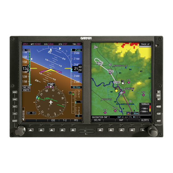
SyStem Overview System Description This section provides an overview of the G500 Avionics Display System. The G500 system is an integrated display system that presents primary flight instrumentation, navigation, and a moving map to the pilot through large- format displays. -
Page 18: Line Replaceable Units (Lru)
1.1.1 Line Replaceable Units (LRU) This guide covers the operation of the GDU 620 as integrated in the G500 system. The G500 Avionics Display System is an advanced technology avionics suite designed to replace the traditional flight instrument cluster. The system combines primary flight instrumentation, navigational information, and a moving map all displayed on dual 6.5 inch color screens. -
Page 19: Gdu 620
Outside Air Temperature (OAT) sensor. The GDC 74A provides pressure altitude, airspeed, vertical speed, and OAT information to the G500 system. The GDC 74A communicates with the GDU 620 and GRS 77 using an ARINC 429 digital interface. -
Page 20: Grs 77
77 and in the Navigation Database are compared, and if the IGRF model in the GRS 77 is out of date, the user is prompted to update the IGRF model in the GRS 77. The prompt will appear after the G500 splash screen is acknowledged on the MFD. -
Page 21: Gtx 330/330D (Optional)
1.1.7 GTP 59 A temperature probe provides Outside Air Temperature (OAT) data to the GDC 74A. The GTP 59 is an example of an appropriate temperature probe. Figure 1-7 GTP 59 Temperature Probe 190-01102-02 Rev. B Garmin G500 Pilot’s Guide... -
Page 22: Gdl 69/69A (Optional)
GAD 43 mimic those of spinning-mass gyros that provide attitude data to the autopilot and allow the gyro to be replaced by the AHRS and GAD 43 combination. Figure 1-9 GAD 43 AHRS Adapter Garmin G500 Pilot’s Guide 190-01102-02 Rev. B... -
Page 23: Gwx 68 Weather Radar
MFD. Figure 1-10 GWX 68 Weather Radar 1.1.11 Garmin Navigator Interface The G500 system requires connection to at least one external Garmin WAAS GPS navigator, such as the 400W/500W series or GNS 480. 1.1.12 Attitude Heading Reference System (AHRS) NOTE: Aggressive maneuvering while AHRS is not operating in normal mode may degrade AHRS accuracy. -
Page 24: Secure Data Cards
1.1.13 Secure Data Cards The G500 System uses Secure Digital (SD) cards to load and store various types of data. For basic flight operations, SD cards are required for Terrain, Obstacle, FliteChart, SafeTaxi, and ChartView database storage as well as Jeppesen aviation and ChartView database updates. -
Page 25: Pilot Controls
1. Press the desired PFD mode selection key (HDG, CRS, ALT, V/S, or BARO). A window will be displayed near the upper right corner of the HSI showing the current value for that mode. 2. Turn the PFD knob to select the desired value. 190-01102-02 Rev. B Garmin G500 Pilot’s Guide... -
Page 26: Pfd Bezel Keys
Altitude Select window. Set the Altitude Bug by turning the PFD knob after pressing the ALT key. Altitude Select Window Current Altitude Altitude Bug Barometric Setting Figure 1-13 Pressing PFD Knob Sets Altitude Select to Current Altitude 1-10 Garmin G500 Pilot’s Guide 190-01102-02 Rev. B... -
Page 27: Pfd Soft Keys
When a soft key function is disabled, the soft key label is subdued (dimmed). Soft keys revert to the previous level after 45 seconds of inactivity. 1-11 190-01102-02 Rev. B Garmin G500 Pilot’s Guide... - Page 28 GPS or VOR/LOC. SYN VIS The SYN VIS soft key is available if Synthetic Vision Technology™ is installed. It enables Synthetic Vision and displays the associated soft keys. 1-12 Garmin G500 Pilot’s Guide 190-01102-02 Rev. B...
-
Page 29: Mfd Knobs
Pressing the Range arrow keys changes the range on the Map pages. The Up arrow zooms out. The Down arrow zooms in. The keys also aid in scrolling up and down text pages. 1-13 190-01102-02 Rev. B Garmin G500 Pilot’s Guide... -
Page 30: Mfd Soft Keys
To select the function indicated on the soft key label, press the soft key directly below the label. Selected Soft Key Unselected Soft Keys Soft Key Labels Soft Keys Figure 1-16 MFD Soft Key Layout 1-14 Garmin G500 Pilot’s Guide 190-01102-02 Rev. B... -
Page 31: System Power Up
NOTE: Refer to Section 6 for system-specific annunciations and alerts. The G500 System is integrated with the aircraft electrical system and receives power directly from electrical busses. The GDU 620 and supporting sub-systems include both power-on and continuous built-in test features that exercise the processor, memory, external inputs, and outputs to ensure safe operation. -
Page 32: Autopilot Test
The optional GAD 43 Adapter provides attitude and heading information from the Garmin GRS 77 Attitude and Heading Reference System to the autopilot. The GAD 43 has the ability to disconnect the autopilot if an error in the GAD 43 output or GRS 77 is detected. -
Page 33: International Geomagnetic Reference Field
Navigation Database are compared, and if the IGRF model in the GRS 77 is out of date, the user is prompted to update the IGRF model in the GRS 77. The following prompt will appear after the G500 splash screen is acknowledged on the MFD. -
Page 34: Navigating Within A Menu
Bezel-Mounted Soft Key Soft Key Labels Soft Keys (Press) Names (Displayed) Figure 1-20 Soft Keys (MFD MAP Page Group) 1-18 Garmin G500 Pilot’s Guide 190-01102-02 Rev. B... -
Page 35: System Settings
1.3.3 System Settings G500 system settings are managed from the Aux Mode System Setup Page. The following settings can be changed: • Display Brightness (Mode and Level) • Airspeed References (Glide, Vr, Vx, and Vy) • PFD Options (Wind Vector) • Dual Unit Synchronization (CDI and Baro) - Dual installations only • Date/Time (Date, Time, Time Format, and Time Offset) - Page 36 Flight plan distances Map range (Traffic Map ranges Page, Terrain DIS, GS, TAS, XTK fields Proximity Page) (Navigation Status Box) CDI scaling All distances on MFD All speeds on MFD 1-20 Garmin G500 Pilot’s Guide 190-01102-02 Rev. B...
-
Page 37: Display Backlighting
1) From the first AUX page, press the small MFD knob to highlight the “DISPLAY BRIGHTNESS” “MODE” box. 2) Turn the small MFD knob to select the desired brightness Level and then press ENTER. 1-21 190-01102-02 Rev. B Garmin G500 Pilot’s Guide... -
Page 38: Dual Gdu 620 Installations
Crossfill Synchronization Settings: • Barometric Correction (default ON) • Selected CDI (default OFF) When Barometric Correction is synchronized, any changes to the Barometric Setting on either GDU will change it on both GDUs. 1-22 Garmin G500 Pilot’s Guide 190-01102-02 Rev. B... -
Page 39: Crossfill Selection
MFD knob to highlight “CDI” or “BARO” in the “Synchronization” box. Figure 1-22 Dual Unit Synchronization 2) Turn the small MFD knob to select “ON” or “OFF.” 3) Press ENT. 1-23 190-01102-02 Rev. B Garmin G500 Pilot’s Guide... - Page 40 This page intentionally left blank 1-24 Garmin G500 Pilot’s Guide 190-01102-02 Rev. B...
-
Page 41: Primary Flight Display (Pfd)
CDI is correct and is the primary means of navigation. This is because the GDU 620 applies magnetic variation corrections for the current aircraft location, but some navigators apply magnetic variation correction for the waypoint location. 190-01102-02 Rev. B Garmin G500 Pilot’s Guide... -
Page 42: Pfd Soft Key Map
The Airspeed Indicator provides Indicated Airspeed, True Airspeed, and Ground Speed. The Airspeed Trend Indicator shows what the airspeed will be in six seconds, if the current rate of acceleration is maintained. The actual airspeed is displayed inside the black pointer. Garmin G500 Pilot’s Guide 190-01102-02 Rev. B... -
Page 43: Markings
The trend vector is absent if the speed remains constant or if any data needed to calculate airspeed is not available due to a system failure. 190-01102-02 Rev. B Garmin G500 Pilot’s Guide... - Page 44 Figure 2-6 Typical Airspeed Tape Markings Figure 2-7 Additional Reference Markings Garmin G500 Pilot’s Guide 190-01102-02 Rev. B...
-
Page 45: Reference Speeds
The Attitude Indicator displays pitch, roll, and slip/ skid information. Roll Pointer Roll Scale Aircraft Symbol Horizon Line Land Representation Pitch Scale Slip/Skid Indicator Sky Representation Roll Scale Zero Figure 2-9 Attitude Indicator 190-01102-02 Rev. B Garmin G500 Pilot’s Guide... - Page 46 In an aircraft with an Attitude Indicator that has a Ground Pointer, the pointer above the Roll Scale shifts with the roll or bank angle of the aircraft to keep the Roll Scale Zero Pointer pointing towards the ground. Garmin G500 Pilot’s Guide 190-01102-02 Rev. B...
-
Page 47: Extreme Attitude
• PFD Knob Mode Annunciations • Ground Speed, True Airspeed, and Airspeed Units • Selected Altitude, Barometer Settings, and Selected Vertical Speed • Vertical Course Deviation Indicator • Traffic and Terrain Annunciations • Flight Director Command Bars 190-01102-02 Rev. B Garmin G500 Pilot’s Guide... - Page 48 Figure 2-13 Extreme Pitch Indication Figure 2-14 Extreme Pitch Indication Figure 2-15 Extreme Pitch Indication Nose Down Nose Up Figure 2-16 Extreme Roll Indication with Display Declutter Garmin G500 Pilot’s Guide 190-01102-02 Rev. B...
-
Page 49: Altimeter
3) Press the center of the PFD knob to set the selected altitude to the current altitude. Selected Altitude in the Selected Altitude Altitude Alerter window Altitude Trend Current Indicator Altitude Barometric Setting Figure 2-17 Altimeter 190-01102-02 Rev. B Garmin G500 Pilot’s Guide... -
Page 50: Altitude Alerting
PFD Knob Selected in Altimeter window Baro Setting Figure 2-19 Barometric Setting 3) Press the PFD knob while in Baro mode to toggle between Standard Pressure (29.92 in) and the currently selected barometric setting. 2-10 Garmin G500 Pilot’s Guide 190-01102-02 Rev. B... -
Page 51: Minimum Descent Altitude/Decision Height Alerting
50 feet above the set altitude minimum value. Yellow When Cyan Within 2500 ft White Within 100 ft Altitude Reached Barometric Minimums Barometric Minimums Figure 2-20 Barometric MDA/DH Alerting Visual Annunciations 2-11 190-01102-02 Rev. B Garmin G500 Pilot’s Guide... - Page 52 To set the descent altitude and enable the Altitude Minimums Bug, refer to Section 3, MFD, Flight Plan Pages. NOTE: If you highlight the minimums Altitude field on the FPL page and hit the CLR key, it will turn the minimums alerting functionality off. 2-12 Garmin G500 Pilot’s Guide 190-01102-02 Rev. B...
-
Page 53: Vertical Speed (V/S) Indicator
1) Press the V/S key to activate Vertical Speed mode. 2) Turn the PFD knob to change the Vertical Speed Bug. 3) Press the center of the PFD knob to set the Vertical Speed value to the current vertical speed. 2-13 190-01102-02 Rev. B Garmin G500 Pilot’s Guide... -
Page 54: Horizontal Situational Indicator
Current Track Indicator Aircraft Symbol Turn Rate/Heading Trend Vector Course Deviation Indicator Current Heading (CDI) Lubber Line Rotating Compass Card OBS Mode Active MSG (Message) on Navigator Figure 2-23 Horizontal Situation Indicator (HSI) 2-14 Garmin G500 Pilot’s Guide 190-01102-02 Rev. B... -
Page 55: Setting The Heading Bug
1) Press the HDG key to activate HDG mode. 2) Turn the PFD knob to change the Heading Bug. 3) Press the PFD knob in HDG mode to set the Heading Bug to the current heading. 2-15 190-01102-02 Rev. B Garmin G500 Pilot’s Guide... -
Page 56: Turn Rate Indicator
If the course deviation data is not valid, the CDI is not displayed. 360º HSI GPS Level of Service Navigation Source Scale Crosstrack Error Figure 2-26 Course Deviation Indicator 2-16 Garmin G500 Pilot’s Guide 190-01102-02 Rev. B... -
Page 57: Changing Cdi Sources
(two dots) while coupled to GPS, the crosstrack error (XTK) is displayed below the white aircraft symbol. VLOC Navigator 1 Navigator 1 VLOC Navigator 2 Navigator 2 Figure 2-27 CDI Navigation Sources 2-17 190-01102-02 Rev. B Garmin G500 Pilot’s Guide... -
Page 58: Changing Cdi Course
2) Turn the PFD knob to change the Course values. 3) Press the PFD knob to set a Course that will center the CDI to the VOR station or waypoint if in GPS OBS mode. 2-18 Garmin G500 Pilot’s Guide 190-01102-02 Rev. B... -
Page 59: Vertical Deviation Indicator (Vdi)
LNAV past the final approach fix (FAF), or the approach only supports LNAV service, “NO GP” is annunciated. Vertical Deviation Source Vertical Deviation Indicator Figure 2-30 Vertical Deviation Indicator (GPS Source) 2-19 190-01102-02 Rev. B Garmin G500 Pilot’s Guide... -
Page 60: Auto-Slewing
GNS navigator and the appropriate frequency is in the active window in the navigator. The G500 will Auto-Slew the HSI course pointer for an ILS, LOC, LOC BC, LDA, or SDF approach when the steps below are completed... - Page 61 5) The CDI and course pointer will change from magenta to green and the pointer will move, or slew, to the final approach course (or 180° from the final approach course for LOC BC approaches). 2-21 190-01102-02 Rev. B Garmin G500 Pilot’s Guide...
-
Page 62: Supplemental Flight Data
The Bearing Information windows are displayed to the lower sides of the HSI and show: • Bearing source (GPS, NAV, or ADF) • Pointer icon (BRG1 = single line, BRG2 = double line) The Bearing Pointer is removed from the HSI if: • The NAV radio is not receiving the tuned VOR station • The NAV radio is tuned to a Localizer frequency 2-22 Garmin G500 Pilot’s Guide 190-01102-02 Rev. B... - Page 63 (such as: GPS, NAV, or ADF). NOTE: The Bearing Line for navigation source 1 (BRG1) will be a single line. The Bearing Line for navigation source 2 (BRG2) will be a double line. 2-23 190-01102-02 Rev. B Garmin G500 Pilot’s Guide...
-
Page 64: Temperature Display
System Setup page. While on the ground, the Wind Vector window will indicate “No Wind Data.” Figure 2-36 Wind Vector with No Wind Data Four styles are available as shown below. Style 1 Style 2 Style 3 Style 4 Figure 2-37 Wind Vector Style 2-24 Garmin G500 Pilot’s Guide 190-01102-02 Rev. B... -
Page 65: Multi-Function Display (Mfd)
GPS navigator. The leg of the active flight plan currently being flown is shown as a magenta line on the navigation map. The other legs are shown in white. 190-01102-02 Rev. B Garmin G500 Pilot’s Guide... -
Page 66: Functional Display Map
Wx Data Link Map 2 XM Info (opt) Wpt Info Traffic (opt) Wx Data Link Map 3 XM Radio (opt) Charts (opt) Terrain (-SVT opt) Weather Radar (opt) System Status Figure 3-2 MFD Page Groups Garmin G500 Pilot’s Guide 190-01102-02 Rev. B... -
Page 67: Mfd Soft Key Map
Vol - Wind Up Standby Vol + Operate Wx Radar Presets Alt Mode Mode Below Normal Control Above PS15 Horizon Unrest Vertical System Status Terrain Back DBASE Inhibit Figure 3-3 MFD Soft Keys 190-01102-02 Rev. B Garmin G500 Pilot’s Guide... -
Page 68: Navigation Map
Traffic Icons Plan Leg with Relative Aircraft Symbol Altitude and Trend (Present Position) Indicator Terrain Symbol Terrain Data Scale Indicates Terrain is Displayed Map Range Page Location Page Name Figure 3-4 MFD Map Description Garmin G500 Pilot’s Guide 190-01102-02 Rev. B... -
Page 69: Default Navigation Map Page
500 feet to 2000 NM. When the map range is decreased to a point that exceeds the capability of the GDU 620 to accurately represent the map, a magnifying glass icon is shown to the left of the map range. 190-01102-02 Rev. B Garmin G500 Pilot’s Guide... -
Page 70: Decluttering Map Pages
DCLTR soft key will toggle through the declutter levels. Features marked with a “•” are shown at the indicated Declutter Level. NOTE: Traffic is automatically decluttered from Nav Map 1 and 2 when the map scale is above 150 NM. Garmin G500 Pilot’s Guide 190-01102-02 Rev. B... - Page 71 • • Class B Airspace • • Water Detail • • • • Class C Airspace • • Active FPL Legs • • • • Table 3-1 Features Shown at Each Decluttering Level 190-01102-02 Rev. B Garmin G500 Pilot’s Guide...
- Page 72 2) Turn the large MFD knob to move the cursor horizontally. Turn the small MFD knob to move the cursor vertically. 3) Press the small MFD knob again to cancel panning. The display will return to the previous map view. Garmin G500 Pilot’s Guide 190-01102-02 Rev. B...
-
Page 73: Selecting Items On The Map
3) Press the INFO soft key (if available) to view more information about the highlighted feature. 4) Press the WX soft key (if available) to view TAF and METAR information. 5) Press the small MFD knob again to return to panning. 190-01102-02 Rev. B Garmin G500 Pilot’s Guide... -
Page 74: Measuring Distances
Distance and Bearing Between Start and End Points Ending Reference Point position Ending Reference Point Starting Reference Point Figure 3-12 Bearing/Distance Measurement 5) Press the small MFD knob to stop measuring. 3-10 Garmin G500 Pilot’s Guide 190-01102-02 Rev. B... -
Page 75: Customizing Navigation Map
Figure 3-14 Navigation Map Page Menu Map Group Selection 4) Press the small MFD knob to return to the Navigation Map Page. 3-11 190-01102-02 Rev. B Garmin G500 Pilot’s Guide... - Page 76 Lat/Lon Off/Range Viewing Range Field of On/Off View** * - shown if the Aviation database is current. ** - shown if Synthetic Vision is available. Table 3-2 Navigation Map Page Menu Selections 3-12 Garmin G500 Pilot’s Guide 190-01102-02 Rev. B...
-
Page 77: Map Feature Options
4) Press the small MFD knob to cancel selection or to end editing and return to the Navigation Map page or turn the large MFD knob to the next option. Map Orientation The Orientation option sets the orientation of the Navigation Map. Figure 3-17 Navigation Map Orientation 3-13 190-01102-02 Rev. B Garmin G500 Pilot’s Guide... - Page 78 North Up. For example, with the 500 NM value selected in the figure below, when the map range of the MFD is 500 NM or more, the map orientation will automatically become North Up. Figure 3-18 Navigation Map “North Up At” Orientation Range Selection 3-14 Garmin G500 Pilot’s Guide 190-01102-02 Rev. B...
- Page 79 3) a point is reached where the Auto Zoom range matches the manual override range (known as auto-sync), 4) Auto Zoom is toggled of and back on in the Navigation Map Setup page, 5) OBS mode is turned off. Figure 3-19 Navigation Map Auto Zoom 3-15 190-01102-02 Rev. B Garmin G500 Pilot’s Guide...
- Page 80 Track and the distance the aircraft will travel in the selected time. Track Vector Aircraft Present Position Figure 3-21 Navigation Map Track Vector 3-16 Garmin G500 Pilot’s Guide 190-01102-02 Rev. B...
- Page 81 The Wind Vector option when turned on will show a box in the top right corner of the MFD indicating the wind direction and speed. Wind Direction Wind Speed Figure 3-23 Navigation Map Wind Vector Display Figure 3-24 Navigation Map Wind Vector Selection 3-17 190-01102-02 Rev. B Garmin G500 Pilot’s Guide...
- Page 82 (25% of the map range). Range Ring Radius Range Ring with Compass Rose Figure 3-25 Navigation Map Range Ring Figure 3-26 Navigation Map Range Ring Selection 3-18 Garmin G500 Pilot’s Guide 190-01102-02 Rev. B...
- Page 83 Traffic, Land Data, Terrain, and Obstacles will still be displayed even with Topo Data turned off. Topo Data Off Topo Data On Figure 3-27 Navigation Map Topo Data Figure 3-28 Navigation Map Topo Data Selection 3-19 190-01102-02 Rev. B Garmin G500 Pilot’s Guide...
- Page 84 Displayed on the Map Sky Indication Range of Topography Current Aircraft Altitude Displayed on the Map Current Ground Level Indication Figure 3-29 Navigation Map Topo Scale Figure 3-30 Navigation Map Topo Scale Selection 3-20 Garmin G500 Pilot’s Guide 190-01102-02 Rev. B...
- Page 85 Terrain has been selected. Terrain Data On Terrain Data Off Terrain Data Terrain Elevation Scale Terrain Data Icon Figure 3-31 Navigation Map Terrain Data Figure 3-32 Navigation Map Terrain Data Selection 3-21 190-01102-02 Rev. B Garmin G500 Pilot’s Guide...
- Page 86 The Terrain Scale option selects whether the Terrain Scale is shown on the Navigation Map. The Terrain scale will be located on the right side of the display. Figure 3-33 Navigation Map Terrain Scale Selection 3-22 Garmin G500 Pilot’s Guide 190-01102-02 Rev. B...
- Page 87 Terrain more than 1000 ft below the aircraft altitude (Black) Figure 3-35 TERRAIN Altitude/Color Correlation Obstacles Within 1000 feet of Aircraft Obstacles Within 100 feet of Aircraft or Above Figure 3-36 Navigation Map Obstacle Data 3-23 190-01102-02 Rev. B Garmin G500 Pilot’s Guide...
- Page 88 Figure 3-37 Navigation Map Obstacle Data Selection 3-24 Garmin G500 Pilot’s Guide 190-01102-02 Rev. B...
- Page 89 Lat/Lon lines will not be shown. In the figure below where 200 NM is selected, Lat/Lon lines will be shown at map ranges of 200 NM and lower. Figure 3-38 Navigation Map Lat/Lon Selection Lat/Lon Reference Information Figure 3-39 Navigation Map Lat/Lon Information 3-25 190-01102-02 Rev. B Garmin G500 Pilot’s Guide...
- Page 90 Field of View The PFD Field of View used for the Garmin Synthetic Vision Technology (SVT™) option (when enabled) can be represented on the MFD Navigation Map Page lateral image. Two dashed lines forming a V-shape in front of the aircraft symbol on the MFD, represent the forward viewing area shown on the PFD.
-
Page 91: Weather Feature Options (Optional)
Viewing range. Weather is an optional feature that requires a GDL 69/69A and an XM Weather subscription. Figure 3-42 Navigation Map Page Menu Figure 3-43 Navigation Map Page Menu Weather Group Selection 3-27 190-01102-02 Rev. B Garmin G500 Pilot’s Guide... - Page 92 In the example below where 150 NM is selected, the NEXRAD Cell Movement will be shown at map ranges of 150 NM and lower. Figure 3-45 NEXRAD Cell Movement Selection 3-28 Garmin G500 Pilot’s Guide 190-01102-02 Rev. B...
- Page 93 In the figure below where 200 NM is selected, Lightning symbols will be shown at map ranges of 200 NM and lower. Figure 3-47 Lightning Viewing Range Selection 3-29 190-01102-02 Rev. B Garmin G500 Pilot’s Guide...
-
Page 94: Traffic Feature Options (Optional)
Figure 3-48 Navigation Map Page Menu Traffic Group Selection 1) While viewing the Navigation Map Setup page and the Traffic Group active, turn the large MFD knob to highlight the “Traffic” options. 3-30 Garmin G500 Pilot’s Guide 190-01102-02 Rev. B... -
Page 95: Aviation Feature Options
The Aviation group selection from the Map Setup Page Menu allows you to customize the display of SafeTaxi information, Runway Extensions, Intersection/ NDB locations, VOR locations, and TFR icons on the Navigation Map. Figure 3-50 Navigation Map Page Menu Aviation Group Selection 3-31 190-01102-02 Rev. B Garmin G500 Pilot’s Guide... - Page 96 Runway Extensions will be shown at and below the selected map range. When Off is selected, Runway Extensions will be shown. Figure 3-52 Navigation Map Runway Extension Selection 3-32 Garmin G500 Pilot’s Guide 190-01102-02 Rev. B...
- Page 97 When Off is selected, the information will not be shown. In the example below where 150 NM is selected, VOR information will be shown at map ranges of 150 NM and lower. Figure 3-54 Navigation Map VOR Viewing Range Selection 3-33 190-01102-02 Rev. B Garmin G500 Pilot’s Guide...
- Page 98 In the example below where 200 NM is selected, Class B/TMA airspace information will be shown at map ranges of 200 NM and lower. Figure 3-55 Navigation Map Class B/TMA Viewing Range Selection 3-34 Garmin G500 Pilot’s Guide 190-01102-02 Rev. B...
- Page 99 In the example below where 200 NM is selected, Class C/TCA airspace information will be shown at map ranges of 200 NM and lower. Figure 3-56 Navigation Map Class C/TCA Viewing Range Selection 3-35 190-01102-02 Rev. B Garmin G500 Pilot’s Guide...
- Page 100 In the example below where 150 NM is selected, Class D airspace information will be shown at map ranges of 150 NM and lower. Figure 3-57 Navigation Map Class D Viewing Range Selection 3-36 Garmin G500 Pilot’s Guide 190-01102-02 Rev. B...
- Page 101 In the example below where 200 NM is selected, Restricted airspace information will be shown at map ranges of 200 NM and lower. Figure 3-58 Navigation Map Restricted Airspace Viewing Range Selection 3-37 190-01102-02 Rev. B Garmin G500 Pilot’s Guide...
- Page 102 In the example below where 200 NM is selected, MOA airspace information will be shown at map ranges of 200 NM and lower. Figure 3-59 Navigation Map MOA (Military) Viewing Range Selection 3-38 Garmin G500 Pilot’s Guide 190-01102-02 Rev. B...
- Page 103 In the example below where 200 NM is selected, Other/ADIZ airspace information will be shown at map ranges of 200 NM and lower. Figure 3-60 Navigation Map Other/ADIZ Viewing Range Selection 3-39 190-01102-02 Rev. B Garmin G500 Pilot’s Guide...
- Page 104 In the example below where 500 NM is selected, TFR information will be shown at map ranges of 500 NM and lower. Figure 3-61 Navigation Map TFR Viewing Range Selection 3-40 Garmin G500 Pilot’s Guide 190-01102-02 Rev. B...
- Page 105 The Airways option allows you to select the airways that are shown on the Navigation Map. All, Low only, and Hi only Airways may be selected. When Off is selected, airways will not be shown. Figure 3-62 Airways Selection 3-41 190-01102-02 Rev. B Garmin G500 Pilot’s Guide...
-
Page 106: Aux Mode Pages
The Aux mode provides pages for System Setup, XM Information (if installed), and system Status. 3.4.1 System Settings G500 system settings are managed from the Aux Mode System Setup Page. The following settings can be changed: • Display Brightness (Mode and Level) • Airspeeds (Glide, V , and V • PFD Options (Wind Vector) -
Page 107: Display Brightness
If you press ENT the Mode setting will be highlighted. 4) With the Mode value highlighted, turn the small MFD knob to select Auto or Manual and then press ENT Figure 3-66 Aux Mode Display Brightness Mode Selection 3-43 190-01102-02 Rev. B Garmin G500 Pilot’s Guide... -
Page 108: Airspeed Reference Marks
2) Turn the small MFD knob to select the value and press ENT Turn the small MFD knob to select 3) The On/Off setting will now be highlighted. On or Off and press ENT . The next value will be highlighted. 3-44 Garmin G500 Pilot’s Guide 190-01102-02 Rev. B... -
Page 109: Pfd Options - Wind Vector
3) When a Wind Vector style is selected, a Wind Vector box with the chosen style will be displayed to the left of the HSI on the PFD. When OFF is selected, the Wind Vector box will not be displayed. 3-45 190-01102-02 Rev. B Garmin G500 Pilot’s Guide... -
Page 110: Synchronization (Dual Installations Only)
MFD knob to highlight “CDI” or “BARO” in the “Synchronization” box in both units. Figure 3-69 Dual Unit Synchronization 2) Turn the small MFD knob to select “ON” or “OFF.” 3) Press ENT. 3-46 Garmin G500 Pilot’s Guide 190-01102-02 Rev. B... -
Page 111: Date And Time
ENT. When Local 12 or 24 hr mode is selected, the Time Offset value will then be highlighted. 3) Turn the small MFD knob to select the desired offset and then press ENT. 3-47 190-01102-02 Rev. B Garmin G500 Pilot’s Guide... -
Page 112: Mfd Display Units
2) Turn the small MFD knob to select Imperial, Metric, or Nautical and then press ENT. The Altitude and Vertical Speed units selection will now be highlighted. 3) Turn the small MFD knob to select Feet or Meters and then press ENT. 3-48 Garmin G500 Pilot’s Guide 190-01102-02 Rev. B... -
Page 113: System Display Units
The Barometric Pressure Setting value will now be highlighted. When True is selected, a "T" will appear to the right of the heading value on the PFD. Figure 3-75 Barometric Setting System Display Units 3-49 190-01102-02 Rev. B Garmin G500 Pilot’s Guide... -
Page 114: Xm Information (Optional)
The Aux mode XM Information page displays information about the XM radios, service, and products when the GDL 69/69A is installed and the XM Radio service is activated. Figure 3-77 XM Information 3-50 Garmin G500 Pilot’s Guide 190-01102-02 Rev. B... -
Page 115: Xm Entertainment Radio (Optional)
1) Turn the large MFD knob to the AUX page group. 2) Turn the small MFD knob to the XM Radio page. Figure 3-78 XM Entertainment Radio A description of XM Entertainment Radio is provided in Section 5 - Additional Features. 3-51 190-01102-02 Rev. B Garmin G500 Pilot’s Guide... -
Page 116: System Status
LRUs. Pertinent information on all system databases is also displayed. Active LRUs are indicated by green check marks; failed LRUs by red “X’ s .” Failed LRUs should be noted and a service center or Garmin-authorized dealer informed. LRU Info Window Database Window... -
Page 117: Flight Plan
Route ESA are shown. DTK, Distance, and ETA from the Previous Leg Current Leg Flight Plan Legs Chart Availability Baro Minimums Window Active Leg Window Figure 3-80 Flight Page 1 (Active Flight Plan) 3-53 190-01102-02 Rev. B Garmin G500 Pilot’s Guide... -
Page 118: Active Flight Plan Detail
Figure 3-81 Active Flight Plan Page Menu Option Selection 3) Turn the large MFD knob to highlight the field you wish to change. Figure 3-82 Active Flight Plan Page Menu Change Fields Option Selection 3-54 Garmin G500 Pilot’s Guide 190-01102-02 Rev. B... -
Page 119: Setting The Altitude Minimums Alerter
GDU 620 and will be synchronized on both units. NOTE: If you highlight the Minimums Altitude field on the FPL page and press the CLR key, it will turn the minimums functionality off. 3-55 190-01102-02 Rev. B Garmin G500 Pilot’s Guide... -
Page 120: Waypoint Information Page
MFD knob and use the large and small MFD knobs to select the identifier for the waypoint. 2) Press the ENT key to select the waypoint. 3) Use the RNG (Range) keys to zoom in or out on the map view. 3-56 Garmin G500 Pilot’s Guide 190-01102-02 Rev. B... -
Page 121: Waypoint Information Detail
In the Frequency window, a scroll bar is shown on the right side of the window when more frequencies are available. Facility Information Window Runway Information Window Airport Frequency Window Figure 3-86 Flight Plan Waypoint Info Detail 3-57 190-01102-02 Rev. B Garmin G500 Pilot’s Guide... - Page 122 MFD knob to activate the cursor. 2) Use the large MFD knob to highlight the Runway and use the small MFD knob to display the available runways. 3) Press the small MFD knob to cancel editing. 3-58 Garmin G500 Pilot’s Guide 190-01102-02 Rev. B...
-
Page 123: Waypoint Weather Information (Optional)
TAF information is displayed only in its raw form. TAF (Terminal Aerodrome Forecast) is the standard format for 24-hour weather forecasts. A TAF typically forecasts significant weather changes, temporary changes, probable changes, and expected changes in weather conditions. 3-59 190-01102-02 Rev. B Garmin G500 Pilot’s Guide... - Page 124 WX soft key to view weather information for the waypoint. 2) Use the small MFD knob or the large MFD knob to scroll through the available information. 3) Press the small MFD knob to return to the main Flight Plan page. 3-60 Garmin G500 Pilot’s Guide 190-01102-02 Rev. B...
-
Page 125: Charts Page (Optional)
Charting Office (NACO). ChartView displays charts published by Jeppesen. ChartView charts are geo-referenced, which allows a pink ownship icon to be overlayed on the chart indicating the aircraft location. Figure 3-91 Flight Page 3 (Charts) 3-61 190-01102-02 Rev. B Garmin G500 Pilot’s Guide... -
Page 126: Viewing Charts
NOTE: When Panning mode is active, scroll bars will be shown on the right side and bottom of the display. 3) Press the small MFD knob to cancel the scroll bars and exit panning. Scroll Bars Figure 3-92 Chart Scroll Bars (Charts) 3-62 Garmin G500 Pilot’s Guide 190-01102-02 Rev. B... -
Page 127: Selecting A New Chart By Airport
3) Use the small MFD knob to change the character. 4) Press ENT to accept the selected airport. 5) Use the large and small MFD knobs to select the desired chart. 6) Press ENT to display the desired chart. 3-63 190-01102-02 Rev. B Garmin G500 Pilot’s Guide... -
Page 128: Selecting A New Chart By Fpl, Nrst, Or Recent
6) If “Auto” is selected, turn the large MFD knob to highlight the Display Level Brightness value. Turn the small MFD knob to change the value and then the ENT key to save the selected value. 3-64 Garmin G500 Pilot’s Guide 190-01102-02 Rev. B... -
Page 129: Hazard Avoidance
The G500 hazard avoidance features are designed to provide advisory information of potential hazards to flight safety associated with weather, terrain, and air traffic. This section is divided into the following groups: Terrain Avoidance • Terrain Proximity • Garmin Terrain-SVT™ (Optional) Traffic Avoidance • Traffic Advisory System (Optional) - Page 130 TAWS Unit. Annunciations are generated from the G500. Table 4-1 G500 Terrain Annunciations NOTE: Obstacles are removed from the Terrain and TAWS pages at ranges greater than 10 NM. Each of the terrain awareness configurations are detailed in the following sub-sections.
-
Page 131: Terrain Proximity
Proximity Garmin TERRAIN is a non-TSO-C151b-certified terrain awareness system provided as a standard feature of GDU 620 to increase situational awareness and help reduce controlled flight into terrain (CFIT). Terrain may be displayed on the Map page group Navigation Map and Terrain pages. -
Page 132: Displaying Terrain Proximity
North Indication Altitude Information Range Rings Ownship Symbol at Present Position Terrain Altitude Legend Page Name 120° 360° Range Ring Selection Selection Figure 4-1 Terrain Page with Aviation Data Displayed and 360° View Garmin G500 Pilot’s Guide 190-01102-02 Rev. B... -
Page 133: Terrain Proximity Page 120° Arc Or 360° Rings
360/Arc soft keys or from the Page Menu. Press the 360 or Arc soft key. Press MENU and the with the View Arc or View 360° selection highlighted press ENT. Figure 4-3 Terrain Page Menu Viewing Selections 190-01102-02 Rev. B Garmin G500 Pilot’s Guide... -
Page 134: Terrain Proximity Page Aviation Data
Terrain or the Map Setup options for the Navigation Map pages. Figure 4-6 Show/Hide Aviation Data on the Terrain Page 2) Press ENT to save the highlighted value. Garmin G500 Pilot’s Guide 190-01102-02 Rev. B... - Page 135 Figure 4-7 Terrain Page with Aviation Data Displayed and 120° Arc View Figure 4-8 Navigation Map Page with Terrain Data Displayed 190-01102-02 Rev. B Garmin G500 Pilot’s Guide...
-
Page 136: Terrain Proximity Limitations
The displayed information should never be understood as being all- inclusive. NOTE: The data contained in the TERRAIN databases comes from government agencies. Garmin accurately processes and cross-validates the data but cannot guarantee the accuracy and completeness of the data. 4.2.3... -
Page 137: External Taws
A TAWS warning received from the GNS 500W Series TAWS unit will be displayed to the left and aligned with the top of the Altitude Tape on the G500 PFD. A new warning will flash for approximately five seconds. Two "R's" in the "TERR N/A"... -
Page 138: Garmin Terrain-Svt™ (Optional)
(Optional) Garmin TERRAIN-SVT™ refers to a subset of Class B TAWS that meets the terrain alerting requirements outlined in Section 7.b of AC 23-26. TERRAIN-SVT is a subset of Class B TAWS that provides a Class B TAWS FLTA functionality with visual alerting and aural alerting. -
Page 139: Garmin Terrain-Svt™ Page 120° Arc Or 360° Rings
4.4.1.1 Garmin Terrain-SVT™ Page 120° Arc or 360° Rings Select the 120º Arc or 360º rings overlay for the Terrain page with either the 360/Arc soft keys or from the Page Menu. Figure 4-10 Terrain-SVT 360 and Arc Views 1. Press the 360 or Arc soft key. -
Page 140: Garmin Terrain-Svt™ Page Aviation Data
4.4.1.2 Garmin Terrain-SVT™ Page Aviation Data Select the display of Aviation data on the Garmin Terrain-SVT page. The Page Menu selections allow you to hide or show aviation data overlay on the Terrain or the Map Setup options for the Navigation Map pages. -
Page 141: Synthetic Vision Alerts And Annunciations
MFD. To acknowledge the pop-up alert: Press the CLR key (returns to the currently viewed page) Press the ENT key (accesses the TERRAIN-SVT Page) Figure 4-14 Terrain-SVT Advisory Pop-Up on the MFD 4-13 190-01102-02 Rev. B Garmin G500 Pilot’s Guide... - Page 142 “Caution, Terrain, Terrain” (RTC-C, ITI-C) FLTA Terrain Warning “Warning, Terrain, Terrain” (RTC-W, ITI-W) FLTA Obstacle Caution “Caution, Obstacle, Obstacle” (ROC-C, IOI-C) FLTA Obstacle Warning “Warning, Obstacle, Obstacle” (ROC-W, IOI-W) Table 4-3 Terrain-SVT Alerts Summary 4-14 Garmin G500 Pilot’s Guide 190-01102-02 Rev. B...
-
Page 143: Tas Traffic (Optional)
4) Select the STANDBY soft key to place the system in the Standby mode. STANDBY is displayed in the Traffic mode field. NOTE: Not all TAS systems can be set to “Standby” mode while in the air. 4-15 190-01102-02 Rev. B Garmin G500 Pilot’s Guide... -
Page 144: Range Ring
Honeywell KTA 810 TAS, KTA 910 2 NM, 6 NM, 12 NM, 24 NM, 40 NM TAS, KMH 820 IHAS, KMH 920 IHAS, and Avidyne TAS 620 (Ryan 9900BX) Table 4-4 Available Traffic Range Ring Steps 4-16 Garmin G500 Pilot’s Guide 190-01102-02 Rev. B... -
Page 145: Altitude Display
3) Press the STANDBY soft key to place the system in the Standby mode. 1) Press the MENU key. 2) Turn the small MFD knob to select one of the following: • BELOW • NORMAL • ABOVE • UNREST (unrestricted) 3) Select the ENT key. 4-17 190-01102-02 Rev. B Garmin G500 Pilot’s Guide... -
Page 146: Tas Symbology
Closing rate, distance, and vertical separation meet TA criteria. A Traffic Advisory that is beyond the selected display range is indicated by a half TA symbol at the edge of the screen at the relative bearing of the intruder. 4-18 Garmin G500 Pilot’s Guide 190-01102-02 Rev. B... -
Page 147: Traffic System Status
Data is not being received from the TAS unit Data is being received from the TAS unit, but the DATA FAILED unit is self-reporting a failure FAILED Incorrect data format received from the TAS unit Table 4-8 TAS Failure Annunciations 4-19 190-01102-02 Rev. B Garmin G500 Pilot’s Guide... - Page 148 NO TRFC DATA Data is not being received from the TAS unit *Shown as symbol on Traffic Map Page **Shown in center of Traffic Map Page Table 4-9 TAS Traffic Status Annunciations 4-20 Garmin G500 Pilot’s Guide 190-01102-02 Rev. B...
-
Page 149: Traffic Pop-Up
NOTE: The traffic pop-up will not appear when your aircraft is on the ground. Press ENT to go directly to the Traffic page. Press CLR to return to the previously viewed page. Traffic Pop-Up Figure 4-16 Traffic Pop-Up 4-21 190-01102-02 Rev. B Garmin G500 Pilot’s Guide... -
Page 150: Tis Traffic (Optional)
Page. When the aircraft is on the ground, TIS automatically enters Standby Mode. Once the aircraft is airborne, TIS switches from Standby to Operating Mode and the GDU 620 begins to display traffic information. 4-22 Garmin G500 Pilot’s Guide 190-01102-02 Rev. B... - Page 151 2) Select Operate Mode (shown if TIS is in Standby Mode) and then press the ENT key. Operating Mode Traffic Advisory, Aircraft is 800 feet above, climbing, and moving away Traffic Advisory, Aircraft is 1000 feet below and moving away Figure 4-17 Traffic Map Page - TIS 4-23 190-01102-02 Rev. B Garmin G500 Pilot’s Guide...
-
Page 152: Tis Symbology
(for speeds greater than 500 fpm in either direction) to the right of the target symbol. Traffic symbols for aircraft without altitude reporting capability appear without altitude separation or climb/descent information. 4-24 Garmin G500 Pilot’s Guide 190-01102-02 Rev. B... -
Page 153: Tis Limitations
4.6.3 TIS Limitations NOTE: This section on TIS Limitations is not comprehensive. Garmin recommends the user review the TIS Limitations section of the Aeronautical Information Manual, Section 1-3-5. TIS is NOT intended to be used as a collision avoidance system and does not relieve the pilot of responsibility to “see and avoid”... - Page 154 Garmin is not responsible for Mode S geographical coverage. Operation of the ground stations is the responsibility of the FAA. Refer to the Aeronautical Information Manual for a Terminal Mode S Radar Site Map covering the U.S. NOTE: TIS will be unavailable at low altitudes in many areas of the U.S., particularly in mountainous regions.
-
Page 155: Tis Alerts
• Traffic or requesting aircraft is below radar coverage. In flat terrain, the coverage extends from about 3000 feet upward at 55 miles. Terrain and obstacles around the radar site can further decrease radar coverage in all directions. • Traffic does not have an operating transponder. 4-27 190-01102-02 Rev. B Garmin G500 Pilot’s Guide... -
Page 156: Traffic Pop-Up
TIS passes the test, TIS enters Standby Mode on the ground or Operating Mode in the air. If TIS fails the power up test, an annunciation is shown in the center of the Traffic Map Page. 4-28 Garmin G500 Pilot’s Guide 190-01102-02 Rev. B... - Page 157 The transponder has failed UNAVAILABLE TIS is unavailable or out of range * Contact a service center or Garmin dealer for corrective action Table 4-11 TIS Failure Annunciations The traffic mode is annunciated in the upper left corner of the Traffic Map Page.
- Page 158 Traffic has not been detected TRFC UNAVAIL The traffic service is unavailable or out of range *Shown as symbol on Traffic Map Page **Shown in center of Traffic Map Page Table 4-13 TIS Traffic Status Annunciations 4-30 Garmin G500 Pilot’s Guide 190-01102-02 Rev. B...
-
Page 159: Xm Weather (Optional)
“Weather Setup” option. Press ENT Figure 4-19 Weather Page Menu Options 2) With the Data Link Setup Menu displayed, turn the Large MFD knob to select the desired item and press ENT. 4-31 190-01102-02 Rev. B Garmin G500 Pilot’s Guide... - Page 160 4) Press ENT to save a selection. 5) Turn the large MFD knob to the next desired option press the small MFD knob to cancel and return to the XM Weather Data Link Map Page. 4-32 Garmin G500 Pilot’s Guide 190-01102-02 Rev. B...
- Page 161 Surface, 3000 feet to 42000 feet County Data Viewing Range Off, 50 NM to 2000 NM Cyclone Data Viewing Range Off, 50 NM to 2000 NM Table 4-14 Weather Page Menu Setup Options 4-33 190-01102-02 Rev. B Garmin G500 Pilot’s Guide...
-
Page 162: Xm Weather Symbols And Product Age
Cloud Top (Cloud Top and Echo Top Mutually Exclusive) XM Lightning Cell Movement 1.25 SIGMETs / AIRMETs METARs City Forecast Surface Analysis Freezing Levels Winds Aloft County Warnings Cyclone Warnings Table 4-15 Weather Product Symbols and Aging Times 4-34 Garmin G500 Pilot’s Guide 190-01102-02 Rev. B... - Page 163 Symbol Description Flood Severe Thunderstorm Tornado Sunny Part Sun Cloudy Rainy T-Storm Snow Windy Foggy Haze High/Low Temp Table 4-16 Weather Symbols 4-35 190-01102-02 Rev. B Garmin G500 Pilot’s Guide...
-
Page 164: Weather Legends
XM Weather Map Menu or pressing the LEGEND soft key on the Weather Map Page. The legend displayed will match the selected weather products. Turn the large or small MFD knobs to scroll through the legend, if necessary. Figure 4-22 Weather Legends 4-36 Garmin G500 Pilot’s Guide 190-01102-02 Rev. B... -
Page 165: Nexrad
This data is composed of the maximum reflectivity from the individual radar sweeps. The display of the information is color-coded to indicate the weather severity level. All weather product legends can be viewed on the Weather Data 4-37 190-01102-02 Rev. B Garmin G500 Pilot’s Guide... -
Page 166: Reflectivity
(Z). NEXRAD measures the radar reflectivity ratio, or the energy reflected back to the radar receiver (designated by the letter Z). The value of Z increases as the returned signal strength increases. 4-38 Garmin G500 Pilot’s Guide 190-01102-02 Rev. B... -
Page 167: Nexrad Limitations
NEXRAD data sampled within the area. The following may cause abnormalities in displayed NEXRAD radar images: • Ground clutter • Strobes and spurious radar data • Sun strobes (when the radar antenna points directly at the sun) • Interference from buildings or mountains, which may cause shadows • Metallic dust from military aircraft, which can cause alterations in radar scans 4-39 190-01102-02 Rev. B Garmin G500 Pilot’s Guide... -
Page 168: Weather Page Map Orientation
1) While viewing a WX Data Link Map page of the WX page group, press the MENU key to display the Page Menu Options . The cursor flashes on the “Weather Setup” option. Press ENT 4-40 Garmin G500 Pilot’s Guide 190-01102-02 Rev. B... -
Page 169: Nexrad Legend
The next option will be highlighted. 4) Press the small MFD knob to cancel selection or to end editing and return to the Navigation Map page or turn the large MFD knob to the next option. 4-41 190-01102-02 Rev. B Garmin G500 Pilot’s Guide... -
Page 170: Echo Tops
ECHO TOPS is selected. Areas where NEXRAD radar coverage and Echo Tops information is not currently available or is not being collected are indicated in grayish-purple. Radar capability exists in these areas, but it is not active or is off-line. 4-42 Garmin G500 Pilot’s Guide 190-01102-02 Rev. B... -
Page 171: Echo Top
The next option will be highlighted. 4) Press the small MFD knob to cancel selection or to end editing and return to the Navigation Map page or turn the large MFD knob to the next option. 4-43 190-01102-02 Rev. B Garmin G500 Pilot’s Guide... -
Page 172: Cloud Tops
Tops is selected for display. Since Cloud Tops and Echo Tops use the same color scaling to represent altitude, display of these weather products is mutually exclusive. When Cloud Tops is activated, Echo Tops or NEXRAD data is not shown. 4-44 Garmin G500 Pilot’s Guide 190-01102-02 Rev. B... - Page 173 Cloud Tops will not be shown. In the figure below where 150 NM is selected, Cloud Top data will be shown at map ranges of 150 NM and lower. Figure 4-31 Cloud Top Viewing Range Selection 4-45 190-01102-02 Rev. B Garmin G500 Pilot’s Guide...
-
Page 174: Xm Lightning
Wx Data Link Map page (1, 2, or 3). When Off is selected, Lightning will not be shown. In the figure above where 300 NM is selected, NEXRAD data will be shown at map ranges of 300 NM and lower. 4-46 Garmin G500 Pilot’s Guide 190-01102-02 Rev. B... -
Page 175: Cell Movement
Figure 4-34 XM Weather - Cell Movement On most applicable maps, Cell Movement data is selected for display along with NEXRAD. On the Weather Data Link Page, Cell Movement data can be selected independently. 4-47 190-01102-02 Rev. B Garmin G500 Pilot’s Guide... - Page 176 Movement will not be shown. In the figure below where 300 NM is selected, Cell Movement data will be shown at map ranges of 300 NM and lower. Figure 4-35 Cell Movement Viewing Range Selection 4-48 Garmin G500 Pilot’s Guide 190-01102-02 Rev. B...
-
Page 177: Sigmets And Airmets
Weather Service. The update rate is every 12 minutes. Figure 4-36 XM Weather - AIRMETs When enabled, the following AIRMETs are available for display: • Icing • Turbulence • IFR conditions • Mountain obscuration • Surface winds 4-49 190-01102-02 Rev. B Garmin G500 Pilot’s Guide... - Page 178 SIGMET/AIRMET will not be shown. In the figure below where 300 NM is selected, SIGMET/AIRMET data will be shown at map ranges of 300 NM and lower. Figure 4-37 SIGMET/AIRMET Viewing Range Selection 4-50 Garmin G500 Pilot’s Guide 190-01102-02 Rev. B...
-
Page 179: Metars
They can also contain information on precipitation amounts, lightning, and other critical data. METARs are shown as colored flags at airports that provide them. Figure 4-38 XM Weather - Graphic METARs 4-51 190-01102-02 Rev. B Garmin G500 Pilot’s Guide... - Page 180 MFD Wx Data Link Map page (1, 2, or 3). When Off is selected, METARs will not be shown. In the figure below where 150 NM is selected, METAR data will be shown at map ranges of 150 NM and lower. Figure 4-39 METAR Viewing Range Selection 4-52 Garmin G500 Pilot’s Guide 190-01102-02 Rev. B...
-
Page 181: Surface Analysis And City Forecast
A Warm Front is where warm air replaces cold air. An orange line with orange half moons that point in the direction of the warm air flow. Figure 4-42 XM Weather - Warm Front 4-53 190-01102-02 Rev. B Garmin G500 Pilot’s Guide... - Page 182 Surface Data will not be shown. In the figure below where 150 NM is selected, Surface data will be shown at map ranges of 150 NM and lower. Figure 4-45 Surface data Viewing Range Selection 4-54 Garmin G500 Pilot’s Guide 190-01102-02 Rev. B...
- Page 183 12, 24, 36, and 48 hours. You may also select an interval by pressing the SRFC TIME soft key on the Wx Data Link Map page. Figure 4-46 Surface Data Time Selection 4-55 190-01102-02 Rev. B Garmin G500 Pilot’s Guide...
-
Page 184: Freezing Level
New data appears at the next update. Figure 4-47 XM Weather - Freezing Levels 4-56 Garmin G500 Pilot’s Guide 190-01102-02 Rev. B... - Page 185 Freezing Level Data will not be shown. In the figure below where 200 NM is selected, Freezing Level data will be shown at map ranges of 200 NM and lower. Figure 4-48 Freezing Level Viewing Range Selection 4-57 190-01102-02 Rev. B Garmin G500 Pilot’s Guide...
-
Page 186: Winds Aloft
42,000 feet MSL. Pressing the WIND DOWN or WIND UP soft keys steps down or up in 3,000 foot increments. Figure 4-49 XM Weather - Winds Aloft Figure 4-50 XM Weather - Winds Aloft Legend 4-58 Garmin G500 Pilot’s Guide 190-01102-02 Rev. B... - Page 187 Winds Aloft will not be shown. In the figure below where 150 NM is selected, Winds Aloft data will be shown at map ranges of 150 NM and lower. Figure 4-51 Winds Aloft Data Viewing Range Selection 4-59 190-01102-02 Rev. B Garmin G500 Pilot’s Guide...
- Page 188 Pressing the WIND DOWN or WIND UP soft keys steps down or up in the 3,000 foot increments. In the figure below where 6000 feet is selected, Winds Aloft data will be shown at 6000 feet and lower. Figure 4-52 Winds Aloft Altitude Selection 4-60 Garmin G500 Pilot’s Guide 190-01102-02 Rev. B...
-
Page 189: County Warnings
County data provides specific public awareness and protection weather warnings from the National Weather Service (NWS). This can include information on fires, tornadoes, severe thunderstorms, flood conditions, and other natural disasters. Figure 4-53 XM Weather - County Warnings 4-61 190-01102-02 Rev. B Garmin G500 Pilot’s Guide... - Page 190 Data will not be shown. In the figure below where 100 NM is selected, County data will be shown at map ranges of 100 NM and lower. Figure 4-54 County Data Viewing Range Selection 4-62 Garmin G500 Pilot’s Guide 190-01102-02 Rev. B...
-
Page 191: Gwx Weather Radar (Optional)
4.8.1 Garmin GWX 68 Radar Description The Garmin GWX 68 Airborne Color Weather Radar is a four color digital pulsed radar with 6.5 kilowatts of power. It combines excellent range and adjustable scanning profiles with a high-definition target display. The pulse width is four microseconds on all ranges except the 2.5 NM range. -
Page 192: Antenna Beam Illumination
15 NM. The curvature of the earth can also be a factor, especially at range settings of 150 NM or more. 4-64 Garmin G500 Pilot’s Guide 190-01102-02 Rev. B... -
Page 193: Radar Signal Attenuation
Radar system can help in identifying these shadowed areas. Areas in question will appear as “shadowed” or gray area on the radar display. Proper use of the antenna tilt control can also help detect radar shadows. 4-65 190-01102-02 Rev. B Garmin G500 Pilot’s Guide... -
Page 194: Radar Signal Reflectivity
A cloud that contains only small raindrops, such as fog or drizzle, will not reflect enough radar energy to produce a measurable target return. Figure 4-57 Precipitation Type and Reflectivity 4-66 Garmin G500 Pilot’s Guide 190-01102-02 Rev. B... -
Page 195: Ground Returns
A large incident angle gives the radar system a smaller detect- able range and lower display intensity due to minimized reflection of the radar energy. 4-67 190-01102-02 Rev. B Garmin G500 Pilot’s Guide... -
Page 196: Operating Distance
All personnel must remain outside of this zone. With a scanning or rotating beam, the averaged power density at the MPEL boundary is significantly reduced. 4-68 Garmin G500 Pilot’s Guide 190-01102-02 Rev. B... -
Page 197: Basic Antenna Tilt Setup
This will place the bottom of the radar beam level with the ground. Return the antenna tilt to the previous setting after a few sweeps. If the aircraft is above 29,000 feet, be cautious of any target return that gets 4-69 190-01102-02 Rev. B Garmin G500 Pilot’s Guide... -
Page 198: Weather Mapping And Interpretation
Weather Mapping and Interpretation 4.8.5.1 Weather display Interpretation When evaluating various target returns on the weather radar display, the colors denote approximate rainfall intensity and rates as shown in the table below. 4-70 Garmin G500 Pilot’s Guide 190-01102-02 Rev. B... -
Page 199: Thunderstorms
“hooks,” “fingers,” or “scalloped” edges. These irregularities may be present in green areas with no yellow, red, or magenta areas and should be treated as highly dangerous areas. Avoid these areas as if they were red or magenta areas. 4-71 190-01102-02 Rev. B Garmin G500 Pilot’s Guide... - Page 200 In areas of multiple heavy cells, use the Vertical Scan feature along with antenna tilt management to examine the areas. Remember to avoid shadowed areas behind targets. Figure 4-63 The “Blind Alley” Vertical Scan 4-72 Garmin G500 Pilot’s Guide 190-01102-02 Rev. B...
-
Page 201: Tornadoes
“dry” (no liquid coating), target returns are less intense. Hail shafts are associated with the same radar target return characteristics as tornados. U-shaped cloud edges 3 to 7 miles across can also indicate hail. 4-73 190-01102-02 Rev. B Garmin G500 Pilot’s Guide... -
Page 202: Radar Operation In Weather Mode
When the weather radar system is in the Weather or Ground Map mode, the system automatically switches to Standby mode on landing. Antenna Operating Stabilization Mode Weather Alert Bearing Line Precipitation Scale Control Window Figure 4-64 Horizontal Scan Display 4-74 Garmin G500 Pilot’s Guide 190-01102-02 Rev. B... -
Page 203: Displaying Weather On The Weather Radar Page
7) Press the RNG keys to select the desired range. 8) The horizontal scan is initially displayed. If vertical scan desired, press the MENU key. Select the VERTICAL menu item and press ENT to change to vertical scanning. 4-75 190-01102-02 Rev. B Garmin G500 Pilot’s Guide... -
Page 204: Vertically Scanning A Storm Cell
Turn the Large MFD knob to highlight the Bearing value. 3) Turn the small MFD knob to place the Bearing Line on the desired storm cell or other area to be vertically scanned. 4-76 Garmin G500 Pilot’s Guide 190-01102-02 Rev. B... -
Page 205: Adjusting The Antenna Tilt Angle
1) While viewing the Weather Radar page of the Wx page group, press the HORIZON soft key. 2) Press the MFD knob. With the Tilt value highlighted in the Control window, turn the small MFD knob to adjust the Tilt and the press ENT. 4-77 190-01102-02 Rev. B Garmin G500 Pilot’s Guide... -
Page 206: Adjusting Gain
2) Turn the large MFD knob to highlight “Manual Gain” and press ENT. This will highlight the Gain value in the Control window. 3) Turn the small MFD knob to adjust the Gain. 4-78 Garmin G500 Pilot’s Guide 190-01102-02 Rev. B... - Page 207 1) While viewing the Weather Radar page of the Wx page group, press the MENU key. 2) Turn the large MFD knob to highlight “Restore Calibrated Gain” and press ENT. Figure 4-71 Restore Calibrated Gain 4-79 190-01102-02 Rev. B Garmin G500 Pilot’s Guide...
-
Page 208: Sector Scan
Figure 4-73 Sector Scan - 40° 6) If desired, readjust the Bearing Line as discussed previously to change the center of the Sector Scan. 7) Remove Sector Scanning by returning the SECTOR SCAN value to FULL. 4-80 Garmin G500 Pilot’s Guide 190-01102-02 Rev. B... -
Page 209: Antenna Stabilization
1) While viewing the Weather Radar page of the Wx page group, press the CONTROL soft key. 2) To activate or deactivate the WATCH™ feature, press the WATCH soft key. 4-81 190-01102-02 Rev. B Garmin G500 Pilot’s Guide... -
Page 210: Weather Alert
If the antenna tilt is adjusted too low, a weather alert can be generated by ground returns. To avoid this issue, set the display range to less than 80 NM in the terminal area. Weather alerts can also be deactivated in the terminal area. 4-82 Garmin G500 Pilot’s Guide 190-01102-02 Rev. B... -
Page 211: Ground Mapping And Interpretation
> 0 dB to < 9 dB YELLOW 9 dB to < 18 dB MAGENTA 18 dB to < 27 dB BLUE 27 dB and greater Table 4-18 Ground Target Return Intensity Levels 4-83 190-01102-02 Rev. B Garmin G500 Pilot’s Guide... - Page 212 5) Turn the large MFD knob to place the cursor in the TILT field. 6) Adjust the antenna tilt angle by turning the small MFD knob to display ground returns at the desired distance. 7) Press the MFD knob to remove the cursor. 4-84 Garmin G500 Pilot’s Guide 190-01102-02 Rev. B...
-
Page 213: Additional Features (Optional)
The optional Garmin Synthetic Vision Technology (SVT™) is a visual enhancement to the G500. SVT is displayed as a forward-looking display of the topography immediately in front of the aircraft. SVT information is shown on the primary flight display (PFD). -
Page 214: Viewing Charts
Figure 5-1 ChartView Chart Page Figure 5-2 FliteChart Chart Page 1) Turn the large MFD knob to the Flight Plan (FPL) page group. 2) Turn the small MFD knob to the Charts page. Garmin G500 Pilot’s Guide 190-01102-02 Rev. B... -
Page 215: Chart Panning
Pan mode and activate scroll bars on the edges of the chart. Turn the large and small MFD knobs to move around the chart. 3) Press the small MFD knob to cancel the scroll bars and exit panning. 190-01102-02 Rev. B Garmin G500 Pilot’s Guide... -
Page 216: Choosing A Chart For The Current Airport
Figure 5-4 Activate Chart Selection for the Current Airport 3) Turn the small MFD knob to highlight the desired chart. Figure 5-5 Choose Chart for the Current Airport 4) Press ENT to accept and view the selected chart. Garmin G500 Pilot’s Guide 190-01102-02 Rev. B... -
Page 217: Selecting A Chart By Identifier
2) Use the large MFD knob to move the cursor to highlight a character. 3) Use the small MFD knob to change the character. 4) Press ENT to accept the selected airport. 190-01102-02 Rev. B Garmin G500 Pilot’s Guide... -
Page 218: Selecting A New Chart By Fpl, Nrst, Or Recent
2) Turn the small MFD knob counterclockwise. 3) Turn the small MFD knob counterclockwise to show FPL, NRST, or RECENT. 4) Turn the large MFD knob to select the desired identifier and then press ENT. Garmin G500 Pilot’s Guide 190-01102-02 Rev. B... -
Page 219: Viewing Chart Notams
4) Turn the small MFD knob to select Day - Auto - Night. 5) Press the small MFD knob or the ENT key to save the selected value and return to the Charts page. 190-01102-02 Rev. B Garmin G500 Pilot’s Guide... -
Page 220: Chartview
See the table below for the various ChartView Power-up Page displays and the definition of each. Power-up Page Display Definition Blank Line. GDU 620 system is not configured for ChartView. Contact a Garmin-authorized service center for configuration. Garmin G500 Pilot’s Guide 190-01102-02 Rev. B... - Page 221 System is verifying chart database when new cycle is installed for the first time. After verifying, chart database is found to be corrupt. ChartView will not be available. Table 5-1 Power-up Page Annunciations and Definitions 190-01102-02 Rev. B Garmin G500 Pilot’s Guide...
- Page 222 Scroll through the database with the MFD knob or ENT key. The ChartView database is provided directly from Jeppesen. Refer to Jeppesen Databases in Appendix A for instructions on revising the ChartView database. 5-10 Garmin G500 Pilot’s Guide 190-01102-02 Rev. B...
-
Page 223: Updating Garmin Databases
National Aeronautical Charting Office (NACO) terminal procedures charts. The charts are displayed with high- resolution and in color for applicable charts. FliteCharts database subscription is available from Garmin. Available data includes: • Arrivals (STAR) • Departure Procedures (DP) • Approaches... - Page 224 180 day viewing period. FliteCharts database has timed out. Database is beyond 180 days after expiration date. FliteCharts database is no longer available for viewing. Table 5-2 FliteCharts Power-up Page Annunciations and Definitions 5-12 Garmin G500 Pilot’s Guide 190-01102-02 Rev. B...
-
Page 225: Safetaxi
Taxiway Identification Hot Spot Outline Aircraft position DCLTR Soft Key Removes Taxiway Markings Figure 5-9 SafeTaxi Depiction on the Navigation Map Page 5-13 190-01102-02 Rev. B Garmin G500 Pilot’s Guide... -
Page 226: Using Safetaxi
MFD knob to activate the cursor. 2. Turn the MFD knobs to move the cursor on the Hot Spot border or into the Hot Spot area and then press the ENT key. 5-14 Garmin G500 Pilot’s Guide 190-01102-02 Rev. B... -
Page 227: Safetaxi ® Cycle Number And Revision
Expires” date is shown in white. When the SafeTaxi cycle has expired, the “SafeTaxi Expires” date appears in yellow. The message “SafeTaxi: N/A” appears in white if no SafeTaxi data is available on the database card. 5-15 190-01102-02 Rev. B Garmin G500 Pilot’s Guide... - Page 228 The EXPIRES date appears in white when data is current and in yellow when expired. SafeTaxi REGION NOT AVAILABLE appears in white if SafeTaxi data is not available on the database card. Expired SafeTaxi data is never disabled. 5-16 Garmin G500 Pilot’s Guide 190-01102-02 Rev. B...
-
Page 229: Xm ® Radio Entertainment
ID or the Data Radio ID, or both, must be provided to XM Satellite Radio to activate the entertainment subscription. The XM Satellite Radio Activation Instructions are included with the unit (also available at www.garmin.com, P/N 190-00355-04). It is not required to activate both the entertainment and weather service subscriptions with the GDL 69A. - Page 230 XM Information Page and a yellow Activation Required message is displayed in the center of the Weather Data Link Page (Map Page Group). The Service Class refers to the groupings of weather products available for subscription. 5-18 Garmin G500 Pilot’s Guide 190-01102-02 Rev. B...
-
Page 231: Xm ® Information
1) In the AUX page group, turn the small MFD knob to display XM Information. 2) The LOCK soft key is used to “lock” your XM subscription activation. This is only used for the initial subscription or to make a change. 5-19 190-01102-02 Rev. B Garmin G500 Pilot’s Guide... -
Page 232: Xm ® Entertainment Radio
2) Turn the small MFD knob to the XM Radio page. Active Channel Window Available Channel Window Channel Scroll Bar Selected Channel Category Window Volume Bar Graph Page Name Soft Keys Figure 5-13 XM Radio 5-20 Garmin G500 Pilot’s Guide 190-01102-02 Rev. B... -
Page 233: Channel Categories
2) Press ALL to show the channels for all categories. Use the large and small MFD knobs to select desired channel. 3) Press ENT to save the selection or press the small MFD knob to cancel selection. 5-21 190-01102-02 Rev. B Garmin G500 Pilot’s Guide... -
Page 234: Selecting An Xm ® Radio Channel
5) Press CHNL and then the DIR CH soft key to directly select a channel in the active category. Use the large and small MFD knobs to select desired channel. 5-22 Garmin G500 Pilot’s Guide 190-01102-02 Rev. B... -
Page 235: Xm ® Radio Volume
Figure 5-18 XM Radio Volume Controls 3) Press MUTE to mute the radio volume. 4) Press MUTE again or the VOL + or VOL – soft keys to unmute the radio volume. 5-23 190-01102-02 Rev. B Garmin G500 Pilot’s Guide... -
Page 236: Xm ® Radio Channel Presets
1) While viewing the XM Radio page of the AUX page group, press the PRESETS soft key. 2) Press the preset soft key for the desired stored channel, such as PS1. 3) Press the MORE soft key to display the next series of presets. 5-24 Garmin G500 Pilot’s Guide 190-01102-02 Rev. B... -
Page 237: Gdl 69/69A Data Link Receiver Troubleshooting
2) Turn the small MFD knob to select the System Status Page (the last page in the AUX Page Group). GDL 69 Status OK LRU Info Window Database Window Scroll Bar for More Items LRU or DBASE Selection Figure 5-20 LRU Status Window 5-25 190-01102-02 Rev. B Garmin G500 Pilot’s Guide... -
Page 238: Autopilot Operation
Operation The G500 is able to interface to certain autopilot systems to provide heading, course, and navigation information in much the same was as a typical HSI. Please refer to your particular autopilot manual for specific information and operation instructions. -
Page 239: Autopilot Navigation
3) Control your autopilot navigation through the navigation source and HSI. Wpt 2 Flight Plan Leg 2 Flight Plan Leg 1 Turn Anticipation Wpt 3 Curve Aircraft Present Position Wpt 1 Figure 5-22 GPSS Turn Anticipation 5-27 190-01102-02 Rev. B Garmin G500 Pilot’s Guide... -
Page 240: Autopilot Operation With The Gdu 620 Emulating Gpss
GDU 620 processes heading information and sends it to the autopilot to emulate what GPSS would normally do. The GPSS/Heading bug inactive annunciation in the lower left corner of the PFD reminds the pilot that the heading bug is not controlling the autopilot. 5-28 Garmin G500 Pilot’s Guide 190-01102-02 Rev. B... - Page 241 This is annunciated next to the HSI by the GPSS annunciation. The Heading bug may still be used for reference, but the autopilot will not control the aircraft via the heading bug. 5-29 190-01102-02 Rev. B Garmin G500 Pilot’s Guide...
-
Page 242: Garmin Synthetic Vision Technology (Svt™) (Optional)
(Optional) The optional Garmin Synthetic Vision Technology (SVT™) is a visual enhancement to the G500. SVT is displayed as a forward-looking display of the topography immediately in front of the aircraft. SVT information is shown on the primary flight display (PFD). The depicted imagery is derived from the aircraft attitude, heading, GPS three-dimensional position, and a database of terrain, obstacles, and other relevant features. - Page 243 GPS data is unavailable. SVT may be restored once the fail conditions are removed by reactivating SVT as explained in the SVT Operation section. Figure 5-24 Synthetic Vision Imagery - PFD 5-31 190-01102-02 Rev. B Garmin G500 Pilot’s Guide...
-
Page 244: Garmin Svt™ Operation
5.7.1 Garmin SVT™ Operation Garmin SVT™ is activated from the PFD using the soft keys located along the bottom edge of the display. Pressing the soft keys turn the related function on or off. SVT functions are displayed on three levels of soft keys. The PFD soft key leads into the PFD function soft keys, including synthetic vision. -
Page 245: Activating And Deactivating Garmin Svt
5.7.2 Activating and Deactivating Garmin SVT™ NOTE: In some instances, such as temporary loss of GPS signal, the SVT functionality will be disabled. To enable SVT: 1) Press the PFD soft key. 2) Press the SYN VIS soft key. 3) Press the SYN TERR soft key to view the SVT display. -
Page 246: Garmin Svt™ Features
The Zero-Pitch Line is drawn completely across the display and represents the aircraft attitude with respect to the horizon. It is not necessarily aligned with the terrain horizon, particularly when the terrain is sloped or mountainous. 5-34 Garmin G500 Pilot’s Guide 190-01102-02 Rev. B... -
Page 247: Horizon Heading
APT SIGNS soft key. Airport Sign without Identifier Airport Sign with Identifier (Between 9 NM and 15 NM) (Between 4.5 NM and 9.0 NM) Figure 5-30 Airport Signs 5-35 190-01102-02 Rev. B Garmin G500 Pilot’s Guide... -
Page 248: Runway Depiction
A runway that is associated with an approach in the loaded flightplan is outlined with a white rectangle, with the actual runway, in that rectangle. See Figure 5-33. Runway Figure 5-33 Depiction of Runway with Loaded Approach 5-36 Garmin G500 Pilot’s Guide 190-01102-02 Rev. B... -
Page 249: Traffic
Traffic symbol coloring and shaping is the same as that used for traffic displayed in the inset moving map or MFD traffic page. Traffic on PFD Traffic on MFD Figure 5-34 Traffic Depiction on PFD and MFD 5-37 190-01102-02 Rev. B Garmin G500 Pilot’s Guide... -
Page 250: Obstacles
FLTA alert. Obstacles greater than 1000 feet below the aircraft’ s altitude are not shown. Obstacles are shown behind the airspeed and altitude displays. 5-38 Garmin G500 Pilot’s Guide 190-01102-02 Rev. B... -
Page 251: Field Of View
MFD with an angle of approximately 50º represent the forward horizontal field of view shown on the PFD. V-Shaped Lines Depict PFD Field of View (angle is approx. 50°) Figure 5-36 MFD and PFD Field of View Comparison 5-39 190-01102-02 Rev. B Garmin G500 Pilot’s Guide... - Page 252 4) Turn the small MFD knob to select On or Off. Press the ENT key to confirm your selection. 5) Press the small MFD knob to return to the Navigation Map Page. 5-40 Garmin G500 Pilot’s Guide 190-01102-02 Rev. B...
-
Page 253: Unusual Attitudes
Two conditions that inhibit SVT and generate alerts on the PFD: • The position of the aircraft exceeds the range of the terrain database. • The terrain database is out of date using an older terrain database card. Blue Band - Sky Representation Figure 5-39 Unusual Attitude Display - Blue Band 5-41 190-01102-02 Rev. B Garmin G500 Pilot’s Guide... - Page 254 Brown Band - Ground Representation Figure 5-40 Unusual Attitude Display - Brown Band Blue Band - Sky Representation Terrain Fills Display Figure 5-41 Blue Sky Bar with Full Display Terrain 5-42 Garmin G500 Pilot’s Guide 190-01102-02 Rev. B...
-
Page 255: Annunciations And Alerts
GPS signal and is not in self-test information. mode. • Heading and • Check AFMS for limitations. attitude data, if • Contact your Garmin dealer for displayed, is still service. valid. • Loss of ADC will cause altitude failure. AHRS1/2 GPS •... - Page 256 • Contact your Garmin dealer for service. AHRS1/2 SRVC • AHRS1 magnetic- • G500 requires service to update field model needs the magnetic field model. update. • Contact your Garmin dealer for service. AHRS1/2 TAS •...
- Page 257 DATA LOST • Pilot stored data • Reset your settings. was lost. Recheck • G500 pilot configurable items have settings. been returned to default settings. DIAG MODE • System is in Diagnostic Mode. EXTERNAL TAWS • External TAWS •...
- Page 258 Alert Message Description Action GAD 43 FAIL • GAD 43 • Contact your Garmin dealer for communication lost. service. GAD 43 • Gyro Emulation Type • Contact your Garmin dealer for Mismatch Fault service. GAD 43 • Yaw Rate Scale •...
- Page 259 GPS1/2 is • Use an alternate navigation inoperative. source. GPS(1/2) PPS • PPS has failed from • Contact your Garmin dealer for FAIL GPS 1/2. service. • The PPS signal has not been received in more than 5 seconds. •...
- Page 260 Action HDG LOST • HDG features disabled or defaulted to GPS1 <LRU> CONFIG • <LRU> config • Contact your Garmin dealer for error. Config service service. required. • <LRU> is not configured correctly. • <LRU> may not function properly. <LRU>...
- Page 261 PFD soft keys. • Terrain DB resolution too low. SW MISMATCH • GDU software • Contact your Garmin dealer for version mismatch. service. Xtalk is off. TERRAIN DSP • Terrain awareness • Error present in <specific display unavailable.
-
Page 262: System Status
Description Action WX RADAR FAIL • Weather radar has • Contact your Garmin dealer for failed. service. Table 6-1 Alert Messages System Status The System Status page of Aux mode shows the status, serial number, and software version of LRUs and the date of databases. There are no menu pages. -
Page 263: Symbols
Soft Surface, Serviced Airport Soft Surface, Non-serviced Airport Private Airport Heliport Intersection LOM (compass locator at outer marker) NDB (Non-directional Radio Beacon) VOR/DME ILS/DME or DME-only VORTAC TACAN Table 7-1 Map Page Symbols 190-01102-02 Rev. B Garmin G500 Pilot’s Guide... -
Page 264: Safetaxi ™ Symbols
Symbols Description Symbol (Highest to Lowest Priority) Traffic Advisory (TA), In Range Traffic Advisory (TA), Out of Range Proximate Advisory (PA) Other Traffic On-Ground Aircraft Ground Non-Aircraft Vehicle Table 7-3 Traffic Symbols Garmin G500 Pilot’s Guide 190-01102-02 Rev. B... -
Page 265: Terrain Obstacle Symbols
Unlighted Obstacle altitude (Red) 1000 ft Terrain between 100 ft and 1000 ft below the aircraft altitude (Yellow) Terrain more than 1000 ft below the aircraft altitude (Black) Figure 7-2 TERRAIN Altitude/Color Correlation 190-01102-02 Rev. B Garmin G500 Pilot’s Guide... -
Page 266: Basemap Symbols
Description Overzoom Indicator Terrain Proximity Enabled and Available Indicator Terrain Proximity Enabled and Not Available Indicator Traffic Enabled and Available Indicator Traffic Enabled and Not Available Indicator Table 7-5 Map Tool Bar Symbols Garmin G500 Pilot’s Guide 190-01102-02 Rev. B... -
Page 267: Xm Weather Tool Bar Symbols
Echo Top (Cloud Top and Echo Top Mutually Exclusive) XM Lightning Cell Movement SIGMETs / AIRMETs METARs City Forecast Surface Analysis Freezing Levels Winds Aloft County Warnings Cyclone Warnings Table 7-6 XM Weather Tool Bar Symbols 190-01102-02 Rev. B Garmin G500 Pilot’s Guide... -
Page 268: Miscellaneous Symbols
MFD Wind Vector (w/ valid GPS solution) PFD Wind Vector styles Parallel Track Waypoint Restricted/Prohibited/Warning/Alert TFR (Temporary Flight Restrictions) Class B Airspace Class C Airspace Class D Airspace User Waypoint Table 7-7 Miscellaneous Symbols Garmin G500 Pilot’s Guide 190-01102-02 Rev. B... -
Page 269: Glossary
The compass direction from the present position to a destination waypoint bearing center runway ºC degrees Celsius Course Deviation Indicator CHNL channel cloud clear CONFIG configuration Course The line between two points to be followed by the aircraft 190-01102-02 Rev. B Garmin G500 Pilot’s Guide... - Page 270 The recommended minimum altitude within ten miles left or right of the desired course on an active flight plan or direct-to enter error En route Safe Altitude Estimated Time of Arrival Estimated Time En Route ºF degrees Fahrenheit Garmin G500 Pilot’s Guide 190-01102-02 Rev. B...
- Page 271 The direction an aircraft is pointed, based upon indications from a magnetic compass or a properly set directional gyro HFOM Horizontal Figure of Merit mercury hectopascal Horizontal Protection Level HSDB High-Speed Data Bus Horizontal Situation Indicator 190-01102-02 Rev. B Garmin G500 Pilot’s Guide...
- Page 272 Magnetic Variation MapMX A proprietary data format used to forward navigation information from the GNS units to the GDU 620 maximum MAXSPD maximum speed (overspeed) barometric minimum descent altitude METAR Aviation Routine Weather Report Garmin G500 Pilot’s Guide 190-01102-02 Rev. B...
- Page 273 Outside Air Temperature Omni Bearing Selector Proximity Advisory personal computer Premature Descent Alert Primary Flight Display P. POS Present Position parallel track quantity right, right runway RAIM Receiver Autonomous Integrity Monitoring random access memory 190-01102-02 Rev. B Garmin G500 Pilot’s Guide...
- Page 274 Synthetic Vision software system true Traffic Advisory TACAN Tactical Air Navigation System Terminal Aerodrome Forecast True Airspeed Traffic Advisory System Total Air Temperature TAWS Terrain Awareness and Warning System Terminal Control Area Garmin G500 Pilot’s Guide 190-01102-02 Rev. B...
- Page 275 VHF Omni-directional Range VORTAC very high frequency omnidirectional range station and tactical air navigation Vertical speed Vertical Speed Indicator WAAS Wide Area Augmentation System WGS-84 World Geodetic System - 1984 waypoint(s) weather XPDR transponder cross-track 190-01102-02 Rev. B Garmin G500 Pilot’s Guide...
- Page 276 This page intentionally left blank Garmin G500 Pilot’s Guide 190-01102-02 Rev. B...
-
Page 277: Sd Card Use And Databases
SD Card Use and Databases The G500 System uses Secure Digital (SD) cards to load and store various types of data. For basic flight operations, SD cards are required for database storage as well as database updates. Jeppesen Databases The navigation database is updated on a 28 day cycle. -
Page 278: Garmin Databases
Garmin Databases NOTE: The data contained in the terrain and obstacle databases comes from government agencies. Garmin accurately processes and cross-validates the data, but cannot guarantee the accuracy and completeness of the data. The following GDU 620 databases are stored on Supplemental Data Cards provided by Garmin: • Terrain – The terrain database contains terrain mapping data. -
Page 279: Updating Garmin Databases
(except for the Jeppesen Navigation Database) is typically inserted into the lower slot on the GDU 620. 3) Apply power to the G500 System. View the MFD power-up splash screen. Check that the databases are initialized and displayed on the splash screen. When updating the terrain and FliteCharts databases, an “in progress”... - Page 280 7) Turn the small MFD knob to scroll through the list and check that all databases are current and there are no errors. If a database is highlighted in yellow, it is either expired or the G500 can not determine the date. 8) Power down the GDU 620.
-
Page 281: Index
BRG 1-2 1-12 Altitude Display Mode 4-16, 4-17 Brightness 1-19, 1-20, 1-21, 3-42, 3-43, Altitude trend vector 2-9 3-64 Angle of incidence 4-67 Annunciations 1-15, 2-10, 2-11, 4-13, 4-19, 4-20, 4-29, 4-30, 5-9, 5-12, 190-01102-02 Rev. B Garmin G500 Pilot’s Guide... - Page 282 Exposure level 4-68 2-19 External TAWS 4-9 Current track indicator 2-14, 2-16 Extreme attitude 2-7 Cursor 1-13, 3-8, 3-9, 3-10, 3-11, 3-43, Extreme Pitch 2-8, 5-41 3-44, 3-45, 7-6 Extreme Roll 2-8 Customizing maps 3-11 Garmin G500 Pilot’s Guide 190-01102-02 Rev. B...
- Page 283 GTX 33 1-2, 1-5, 4-1 Land data 3-4, 3-12, 3-16, 3-19 GTX 330/330D 1-2, 1-5 Lateral deviation scale 2-14, 2-16 GWX 68 1-1, 1-2, 1-7, 3-1, 4-1, 4-63 Lat/Lon 3-7, 3-8, 3-11, 3-12, 3-25, 3-56 190-01102-02 Rev. B Garmin G500 Pilot’s Guide...
- Page 284 Minimum Descent Altitude (MDA) 2-11, 2-12 4-27, 5-38, 7-3, A-2 Miscellaneous symbols 7-6 Obstructions 4-8 Occluded front 4-54 MOA 3-7, 3-12, 3-38, 7-6 On ground aircraft 7-2 Moving map 1-1, 1-3, 1-13, 1-14, 1-18, Garmin G500 Pilot’s Guide 190-01102-02 Rev. B...
- Page 285 Software version 3-52, 5-25, 6-8 4-82 Speed 1-3, 1-19, 1-20, 2-2, 2-3, 2-5, 2-7, RECENT 3-64, 5-6 2-13, 3-17, 3-42, 3-44, 3-48, 4-24 Record of Revisions vi Speed range 2-3 Reference speed 2-5 STAB 4-81 190-01102-02 Rev. B Garmin G500 Pilot’s Guide...
- Page 286 Terrain scale 3-12, 3-22, 4-5 Vertical Speed Indicator (VSI) 1-21, 2-13 Terrain-SVT iv, 4-1, 4-2, 4-10 VNAV 2-19, 2-23 VNV 8-7 TFR 3-4, 3-12, 3-31, 3-40, 7-6 Voice alert 4-27 Thunderstorms iii, 4-35, 4-61, 4-66, 4-70, Garmin G500 Pilot’s Guide 190-01102-02 Rev. B...
- Page 287 WX soft key 3-9, 3-54 XM 3-50, 3-51, 4-31, 5-17 XM channel categories 5-21 XM entertainment radio 5-17 XM radio activation 5-17 XM radio channel presets 5-24 XM radio channels 5-22 XM radio volume 5-23 190-01102-02 Rev. B Garmin G500 Pilot’s Guide...
- Page 288 This page intentionally left blank Garmin G500 Pilot’s Guide 190-01102-02 Rev. B...
- Page 290 © 2009 GARMIN Corporation GARMIN International, Inc. 1200 East 151 Street, Olathe, Kansas 66062, U.S.A. Tel. 913/397.8200 or 800/800.1020 Fax 913/397.8282 Garmin AT, Inc. 2345 Turner Rd., S.E., Salem, Oregon 97302, U.S.A. Tel. 503/581.8101 or 800/525.6726 Fax. 503/364.2138 Garmin (Europe) Ltd.