Garmin G500 Reference Manual
Avionics display systems
Hide thumbs
Also See for G500:
- Pilot's manual (410 pages) ,
- Instructions manual (334 pages) ,
- Reference manual (90 pages)
Table of Contents
Advertisement
Quick Links
Advertisement
Table of Contents

Related Manuals for Garmin G500


Summary of Contents for Garmin G500
- Page 1 G500/G600 Cockpit Reference Guide...
- Page 2 ® ® ® SVT™, G500, and G600 are trademarks of Garmin Ltd. or its subsidiaries. These trademarks may not be used without the express permission of Garmin. NavData is a registered trademark of Jeppesen, Inc., ChartView™ is a trademark of Jeppesen, Inc.: ®...
-
Page 3: Aviation Limited Warranty
Garmin in lieu of repair. Within the applicable period, Garmin will, at its sole option, repair or replace any components that fail in normal use. Such repairs or replacement will be made at no charge to the customer for parts or labor, provided that the customer shall be responsible for any transportation cost. - Page 4 Although unlikely, it may be possible for erroneous operation to occur without a fault indication shown by the G500/G600. It is thus the responsibility of the pilot to detect such an occurrence by means of cross-checking with all redundant or correlated information available in the cockpit.
- Page 5 WARNING: To reduce the risk of unsafe operation, carefully review and understand all aspects of the G500/G600 Pilot’s Guide. Thoroughly practice basic operation prior to actual use. During flight operations, carefully compare indications from the G500/G600 to all available navigation sources, including the information from other NAVAIDs, visual sightings, charts, etc.
- Page 6 GDU 620. WARNING: Because of anomalies in the earth’s magnetic field, operating the G500/G600 within the following areas could result in loss of reliable attitude and heading indications. North of 72° North latitude and south of 70° South Latitude. An area north of 65° North latitude and between longitude 75°...
- Page 7 NOTE: All visual depictions contained within this document, including screen images of the GDU 620 bezel and displays, are subject to change and may not reflect the most current G500/G600 system. Depictions of equipment may differ slightly from the actual equipment.
- Page 8 This notice is being provided in accordance with California’s Proposition 65. If you have any questions or would like additional information, please refer to our website at www.garmin.com/ prop65. NOTE: Terrain data is not displayed when the aircraft latitude is greater than 75°...
- Page 9 Revision Date Description 10/13/16 Update reflects software v7.12 upgrade. 04/10/15 Update reflects software v7.00 upgrade. Combined G500 and G600 CRGs. 10/23/12 Update reflects software v6.11 upgrade. 08/23/11 Update reflects software v6.00 upgrade. 11/30/10 Upgrade reflects software v4.00 and v5.00 upgrade.
- Page 10 Updated V Speed References on Airspeed Tape image. Updated the synchronization note and option image Added User Waypoint and VRP (Visual Reporting Point) symbols to the Map Page Symbols table. Updated Terrain/Obstacle Altitude section. G500/G600 Cockpit Reference Guide viii 190-00601-03 Rev H...
-
Page 11: Table Of Contents
MFD Soft Key Map ............................28 Map Group ..................... 29 Navigation Map 1 and Navigation Map 2 Pages ..................29 Decluttering (DCLTR) the Map Pages ......................30 Split Screen Page (Optional) ........................34 Traffic Map Page (Optional) ........................35 Terrain/TAWS-B Page ..........................41 G500/G600 Cockpit Reference Guide 190-00601-03 Rev H... - Page 12 XM Weather Map Pages ..........................44 Customizing the Weather Map ........................44 Changing Forecast Time ..........................46 Changing Weather Altitude .........................46 Garmin Flight Data Services (GFDS) Map Pages ...................47 FIS-B Weather Map Pages ...........................49 Customizing the Weather Map ........................49 Weather Radar (Optional) ................51 Weather Radar Map Page ...........................51...
-
Page 13: Introduction
Each LRU has a particular function, or set of functions, that contributes to the system’ s operation. For more details on the G500 and G600 systems, refer to the latest revision of the G500/G600 Pilot’ s Guide, P/N 190-00601-02. -
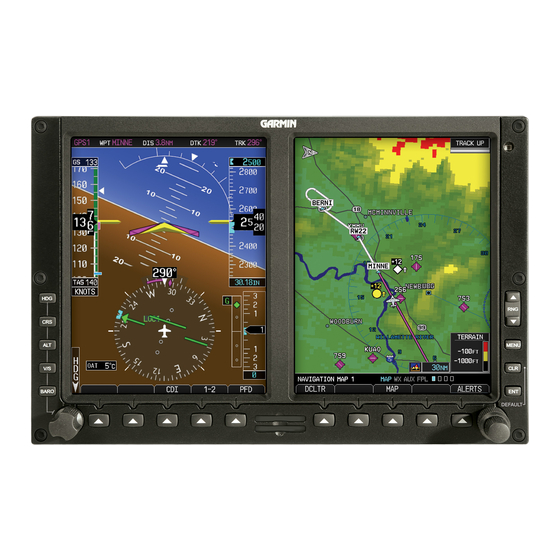
Page 14: Primary Flight Display (Pfd)
Altitude Select Key: Press ALT and turn PFD knob to set altimeter bug. V/S (Vertical Speed) Select Key: Press V/S and turn PFD knob to set V/S bug. Barometer Select Key: Press BARO and turn PFD knob to change barometric setting. G500/G600 Cockpit Reference Guide 190-00601-03 Rev H... - Page 15 (slip/skid). Altitude Tape: Displays Current Altitude, Altitude Trend, Altitude Bug, Altitude or Radar Altimeter Minimums Bug, and BARO setting. Marker Beacon: Marker Beacon Indicator. Clock or Timer window. G500/G600 Cockpit Reference Guide 190-00601-03 Rev H...
-
Page 16: Airspeed Tape
Groundspeed Trend Indicator Current Airspeed True Airspeed Airspeed Tape White triangle Typical Airspeed Tape Markings (Refer to AFM/POH) Overspeed Maximum speed with landing gear extended. Overspeed Indication Additional Reference Markings Reference Speeds G500/G600 Cockpit Reference Guide 190-00601-03 Rev H... - Page 17 Glide Reference Marker Reference Marker Reference Marker Reference Marker Reference Speeds The labels for the reference markers may vary as configured during installation. Reference Marker Reference Marker Reference Marker Reference Marker Alternate Reference Speeds G500/G600 Cockpit Reference Guide 190-00601-03 Rev H...
-
Page 18: Altitude Tape
To change the BARO setting, press the BARO key and turn the PFD knob to the desired pressure. To select standard pressure (29.92in, 1013 mb), press the PFD knob. To return to the previous setting, press the PFD knob again. G500/G600 Cockpit Reference Guide 190-00601-03 Rev H... -
Page 19: Minimum Descent Altitude/Decision Height Alerting
150 feet above the setting for the alert. NOTE: If you highlight the minimums Altitude field and press the CLR key, it will turn the minimums alerting functionality off. G500/G600 Cockpit Reference Guide 190-00601-03 Rev H... - Page 20 2) Turn the small MFD knob to select Off, BARO, or RAD ALT. 3) Press the ENT key to move to enter altitude. Turn the small MFD knob to enter the desired altitude. Press the ENT key to confirm selection. G500/G600 Cockpit Reference Guide 190-00601-03 Rev H...
-
Page 21: Altitude Bug
The Fast/Slow indication from an external system may be optionally displayed on the left side of the PFD. Refer to the Airplane Flight Manual for instructions on using the Fast/Slow indications. Pointer Fast/Slow Scale Fast/Slow Scale and Pointer G500/G600 Cockpit Reference Guide 190-00601-03 Rev H... -
Page 22: Wind Vectors
Vertical Speed Maximum and Minimum ranges will be shown on the left side of the Vertical Speed tape. Max Vertical Speed Vertical Speed Bug Current Vertical Speed Min Vertical Speed Vertical Speed Bug Setting Vertical Speed (V/S) Tape and Window G500/G600 Cockpit Reference Guide 190-00601-03 Rev H... -
Page 23: Vertical Deviation Indicator (Vdi)
• Difference from International Standard Atmosphere (ISA) – This is the difference between SAT and standard (ISA) temperature at the current altitude. This provides an indication of how much warmer/colder the temperature is from a “standard” atmosphere. G500/G600 Cockpit Reference Guide 190-00601-03 Rev H... -
Page 24: Dme Indication
Roll Scale Zero Pointer pointing towards the ground. Roll Scale Zero Pointer Roll Pointer Roll Scale Attitude Indicator with a Ground Pointer Configuration in a Left Turn G500/G600 Cockpit Reference Guide 190-00601-03 Rev H... -
Page 25: Horizontal Situation Indicator (Hsi): Aircraft Heading
The top of the HSI displays current heading, current GPS track (magenta diamond), heading trend, and turn rate markings. The heading trend indicates the rate of turn. Marking for rate of turn are provided at half-standard (1.5°/sec) and standard (3°/sec) rate. G500/G600 Cockpit Reference Guide 190-00601-03 Rev H... -
Page 26: Adjusting The Course Pointer
ADF source is installed. The BRG2 soft key cycles through modes, NAV2 and GPS2 if a second NAV or GPS source is available. Additionally, ADF is available if an ADF source is installed. G500/G600 Cockpit Reference Guide 190-00601-03 Rev H... - Page 27 BRG 2 bearing pointer Bearing Pointers on the HSI GPS1 GPS2 TERM VOR1 CDI Source GPS Mode VOR2 LNAV LOC1 LNAV+V LOC2 L/VNAV GPS Advisory Suspend LP +V 1.00nm 0.30nm SUSP PFD HSI Annunciations G500/G600 Cockpit Reference Guide 190-00601-03 Rev H...
-
Page 28: Marker Beacon Annunciations
SUSP: Displays when automatic waypoint sequencing on the interfaced GPS unit is suspended. Marker Beacon Annunciations Marker Beacon Location Marker Beacon Location Marker Beacons Current Icon (Standard) Icon (Blink) Beacon Inner Marker Middle Marker Outer Marker G500/G600 Cockpit Reference Guide 190-00601-03 Rev H... -
Page 29: Miscompare Annunciations
PRIMARY FLIGHT DISPLAY (PFD) Miscompare Annunciations For complete description and conditions of miscompare annunciations, refer to the G500/G600 Pilot’ s Guide, P/N 190-00601-02. Pitch and Roll Miscompare Pitch Miscompare Roll Miscompare Miscompare Annunciations G500/G600 Cockpit Reference Guide 190-00601-03 Rev H... - Page 30 NOTE: Verify the navigation source by the indication on the HSI. NOTE: The selected navigator is the source for all PFD and MFD functions, except for bearing pointers and external TAWS PFD annunciations. G500/G600 Cockpit Reference Guide 190-00601-03 Rev H...
-
Page 31: Autopilot (Ap)
PRIMARY FLIGHT DISPLAY (PFD) Autopilot (AP) The G500/G600 is able to interface to certain autopilot systems to provide the functions described in this section. Please refer to your particular Airplane Flight Manual and autopilot documentation for specific information and operating instructions. -
Page 32: Heading
1) Set your navigation source and HSI to the desired course. 2) Engage your autopilot in navigation mode. 3) Control your autopilot navigation through the navigation source and the HSI. G500/G600 Cockpit Reference Guide 190-00601-03 Rev H... -
Page 33: Gpss
PFD. The GPSS mode annunciation depends on the location of the NAV STATUS information, as shown in the following figure. NAV Status Style 2 NAV Status Style 1 GPSS Mode Annunciations G500/G600 Cockpit Reference Guide 190-00601-03 Rev H... -
Page 34: Flight Director Display
VS key on the PFD. The vertical speed mode may be alternately engaged or disengaged by pressing and holding the VS key on the PFD bezel. Engage/Disengage VS Bug G500/G600 Cockpit Reference Guide 190-00601-03 Rev H... -
Page 35: Autopilot Mode Annunciations
When autopilot annunciations are displayed at the top of the PFD, the Nav Status information will be located to the left of the HSI (NAV STATUS Style 2). Autopilot Status Roll Modes Pitch Modes Active Mode Active Mode Armed Mode Armed Mode Autopilot Annunciations G500/G600 Cockpit Reference Guide 190-00601-03 Rev H... -
Page 36: Additional Features
Synthetic Vision Technology ™ Synthetic Vision Technology (SVT) is offered as a feature to the G500/G600. SVT is primarily comprised of a computer-generated forward-looking, attitude aligned view of the topography immediately in front of the aircraft from the pilot’ s perspective. -
Page 37: Displaying Svt ™ Terrain
PRIMARY FLIGHT DISPLAY (PFD) The following features are part of the Synthetic Vision Technology. For more details refer to the G500/G600 Pilot’ s Guide, Rev. G or later. • Flight Path Marker • Airport Signs • Horizon Heading Marks • Runway Display •... -
Page 38: Multi-Function Display (Mfd)
Menu: Displays configuration items for each page of the page groups. Range Select: Changes the range on the map pages. Up arrow zooms out, down arrow zooms in. Also aids in scrolling up and down text pages. G500/G600 Cockpit Reference Guide 190-00601-03 Rev H... -
Page 39: Page Navigation - Moving Between Pages
5) Press ENT to accept displayed value or press the small MFD knob to cancel selection or exit the editing mode. Default Map Page Press and hold the CLR key to return to the first page of the MAP group. G500/G600 Cockpit Reference Guide 190-00601-03 Rev H... -
Page 40: Mfd Soft Key Map
DB ACTV Send Answer Hang Up DB SYNC Keys 1234 5678 90*# Active Fpl Wpt Info Charts ALERTS INFO/MAP Header Info NOTAM Plan Rwy/Freq TRND/ACK Detail Profile APT DIR CAPTURE Minimums Select WX/NOTAM BACK G500/G600 Cockpit Reference Guide 190-00601-03 Rev H... -
Page 41: Map Group
3) Press the INFO soft key (if available) to view more information about the highlighted waypoint. 4) Press the WX soft key (if available) to view TAF and METAR information. Press the small MFD knob again to return to the map. G500/G600 Cockpit Reference Guide 190-00601-03 Rev H... -
Page 42: Decluttering (Dcltr) The Map Pages
Distance, Bearing and Coordinates Display Measuring Map Pointer 4) Press ENT to reset the distance and bearing values. 5) Press the small MFD knob to stop measuring. G500/G600 Cockpit Reference Guide 190-00601-03 Rev H... - Page 43 8) Repeat the above steps to set preferences for the remaining groups. NOTE: In the Map Options Setup section, the selected range is defined as the map range below which the display feature will be visible. G500/G600 Cockpit Reference Guide 190-00601-03 Rev H...
- Page 44 WEATHER • NEXRAD Source (CONUS, REGIONAL, or Combined) • Stormscope Viewing Range (Off to 500 NM) STORMSCOPE • Strke/Cell Mode (Cell or Strike) TRAFFIC • Traffic Mode (Off, All Traffic, TA/PA, TA Only) G500/G600 Cockpit Reference Guide 190-00601-03 Rev H...
- Page 45 Airport Moving Map Display (AMMD). SafeTaxi and ChartView are intended to improve pilot situational awareness during ground operations and should only be used by the flight crew to orient themselves on the airport surface. G500/G600 Cockpit Reference Guide 190-00601-03 Rev H...
-
Page 46: Split Screen Page (Optional)
Display of External Video Source Map Display External Video 2) The External Video page will show the external video on the top half of the MFD and a Navigation Map will be shown on the lower half. G500/G600 Cockpit Reference Guide 190-00601-03 Rev H... -
Page 47: Traffic Map Page (Optional)
CLR key. Press the ENT key to go to the traffic page. The traffic pop-up window will be removed when the traffic alert is no longer active. Traffic Traffic Annunciation Traffic Pop-Up PFD Traffic Display MFD Traffic Pop-Up Window G500/G600 Cockpit Reference Guide 190-00601-03 Rev H... - Page 48 NOTE: Depending on your traffic configuration, the OPERATE and STANDBY soft keys may not be available. Traffic Mode Field Altitude Mode Field NOTE: Some traffic systems will not enter standby mode while airborne. G500/G600 Cockpit Reference Guide 190-00601-03 Rev H...
- Page 49 2) Verify that a traffic message is shown next to the altitude tape on the PFD and that the traffic pop-up is displayed on the MFD. After a few seconds, test mode is exited automatically by the traffic system. Traffic Annunciation Traffic Annunciation on PFD G500/G600 Cockpit Reference Guide 190-00601-03 Rev H...
- Page 50 Mode Traffic Advisory, Aircraft is 1200 feet above, climbing, and moving in the direction of the line Other Traffic, Aircraft is 3000 feet above, climbing, and moving in the direction of the line G500/G600 Cockpit Reference Guide 190-00601-03 Rev H...
- Page 51 Target Duration NOTE: ADS-B targets will be shown as the filled-in icon when they are within 6NM laterally and 1200 ft vertically of the ownship; otherwise, they are shown as the hollow icons. G500/G600 Cockpit Reference Guide 190-00601-03 Rev H...
- Page 52 Relative motion vectors are yellow for TAs and otherwise are green. The annunciation on the bottom of the dedicated traffic page indicates which vector type is selected and their length. NOTE: Relative motion vectors are not available on the ground. G500/G600 Cockpit Reference Guide 190-00601-03 Rev H...
-
Page 53: Terrain/Taws-B Page
Terrain/TAWS-B Page (Optional) Soft Keys Found on Terrain/TAWS-B Page VIEW INHIBIT Garmin provides the following Terrain/TAWS selections, based upon your system configuration. WARNING: Do not use Terrain-SVT information for primary terrain avoidance. Terrain-SVT is intended only to enhance situational awareness. - Page 54 Class B TAWS FLTA functionality, including visual alerting and aural alerting. Terrain-SVT is provided with the Synthetic Vision functionality and not marketed separately. Garmin Terrain-SVT is available in GDU 620 v3.00 or later, with SVT enabled. • TAWS-B - is an optional feature developed that meets the terrain alerting and ground proximity requirements for Class B TAWS system as defined in TSO-C151b.
-
Page 55: Terrain Pop-Up Alerts
MFD. To acknowledge the pop-up alert and return to the currently viewed page, press the CLR key. To acknowledge the pop-up alert and go to the TAWS-B page, press the ENT key. G500/G600 Cockpit Reference Guide 190-00601-03 Rev H... -
Page 56: Wx Group
3) Turn the large MFD knob to select desired item to change. Turn the small MFD knob to set the preference of the weather feature option. 4) Press ENT to confirm your selection. 5) To return to the XM Weather Map page, press the small MFD knob. G500/G600 Cockpit Reference Guide 190-00601-03 Rev H... - Page 57 NEXRAD Data and Echo Top Data at the same time. NOTE: Due to similarities in color schemes, it is not possible to display Echo Top Data and Cloud Top Data at the same time. G500/G600 Cockpit Reference Guide 190-00601-03 Rev H...
-
Page 58: Changing Forecast Time
WX Alt Up/Dn soft keys. Press the WX Alt Dn or WX Alt Up soft keys to cycle through the available forecast periods as shown on the right side of the weather page. G500/G600 Cockpit Reference Guide 190-00601-03 Rev H... -
Page 59: Garmin Flight Data Services (Gfds) Map Pages
Prior to requesting GFDS information, an access code and system ID will need to be assigned. For more information on GFDS and how to register, refer to the latest revision of the G500/G600 Pilot’ s Guide, P/N 190-00601-02. After registering you are able to display GFDS data: 1) While viewing any one of the three pages of the WX Group, press the MENU button. - Page 60 3) Turn the large MFD knob to the Manual Request box and press ENT to either send request or cancel current request. 4) Press the small MFD knob to return to the GFDS page. G500/G600 Cockpit Reference Guide 190-00601-03 Rev H...
-
Page 61: Fis-B Weather Map Pages
3) Turn the large MFD knob to select the desired item to change. Turn the small MFD knob to set the preference of the weather feature option. 4) Press ENT to confirm your selection. 5) To return to the FIS-B Weather Map page, press the small MFD knob. G500/G600 Cockpit Reference Guide 190-00601-03 Rev H... - Page 62 Off, 10 NM to 500 NM METAR Data Viewing Range Off, 10 NM to 500 NM Wnds Aloft Data Viewing Range Off, 10 NM to 500 NM TFR Data Viewing Range Off, 10 NM to 500 NM G500/G600 Cockpit Reference Guide 190-00601-03 Rev H...
-
Page 63: Weather Radar (Optional)
WX GROUP Weather Radar (Optional) Weather Radar Map Page Soft Keys Found on Weather Radar Map Page Operating Operating Mode Mode Weather Alert (GWX only) Control Precipitation Window Scale Weather Radar Display G500/G600 Cockpit Reference Guide 190-00601-03 Rev H... -
Page 64: Airborne Color Weather Radar
WARNING: Begin transmitting only when it is safe to do so. If transmitting on the ground is necessary, ensure that no personnel or objects are within the minimum safe distance from the radar antenna. For Garmin GWX radars, the minimum safe distance may be up to 14 feet. For 3rd-party radars, refer to the radar pilot’s guide or other manufacturer documentation to... -
Page 65: Adjusting Gain
MFD knob to adjust the line. Adjusting Gain WARNING: Changing the gain in Weather Mode (Garmin GWX units only) causes precipitation intensity to be displayed as a color not representative of the true intensity. Remember to return the gain setting to “Calibrated”... -
Page 66: Antenna Stabilization
Ground Clutter Suppression reduces the amount of returns as a result of highly reflective objects on the ground, such as buildings or cities, while maintaining the intensity and size of weather returns. his optional feature requires a separate enablement. Contact your dealer for details. G500/G600 Cockpit Reference Guide 190-00601-03 Rev H... -
Page 67: Aux Group
2) Press the RNG (Range) keys to zoom in and out. The range of the zoom feature is 1x up to 10x. 3) Press the small MFD knob to exit. Setup Soft Key Full Soft Key Video Soft Keys G500/G600 Cockpit Reference Guide 190-00601-03 Rev H... -
Page 68: System Setup Page
V Speed References on Airspeed Tape Airspeed References NOTE: At any time during the setting of your airspeed references, pressing the DFLT SPD soft key will restore the unit to its initial configuration. G500/G600 Cockpit Reference Guide 190-00601-03 Rev H... - Page 69 1) While viewing the System Setup page of the AUX page group, press the small MFD knob to activate the cursor. 2) Turn the large MFD knob to highlight the desired NAV Status value. 3) Turn the small MFD knob to select the style and press ENT G500/G600 Cockpit Reference Guide 190-00601-03 Rev H...
- Page 70 ON or OFF. Turn the small MFD knob to turn the synchronization of databases ON or OFF. 3) Press ENT to move to the DATE/TIME box or press the small MFD knob to exit the editing mode. Synchronization Option G500/G600 Cockpit Reference Guide 190-00601-03 Rev H...
- Page 71 -4 hours -3 hours Eastern -5 hours -4 hours Central -6 hours -5 hours Mountain -7 hours -6 hours Pacific -8 hours -7 hours Alaskan -9 hours -8 hours Hawaiian -10 hours -9 hours G500/G600 Cockpit Reference Guide 190-00601-03 Rev H...
- Page 72 1) While viewing the System Setup Page of the Aux Page Group, press the small MFD knob and turn the large MFD knob to move to the desired field of the SYSTEM DISPLAY UNITS box. G500/G600 Cockpit Reference Guide 190-00601-03 Rev H...
- Page 73 Press the RA TEST soft key (if available) to activate the radar altimeter test. An RA TEST annunciation will be displayed on the PFD. For more information on the Radar Altimeter and its settings, refer to the latest revision of the G500/ G600 Pilot’ s Guide, P/N 190-00601-02.
-
Page 74: Xm ® Information Page (Optional)
Information screen. This page contains the Data Radio and Audio Radio IDs. The only option on this page is to LOCK in your information once your subscription has been activated. XM Information Page G500/G600 Cockpit Reference Guide 190-00601-03 Rev H... -
Page 75: Xm ® Radio Page (Optional)
MFD knob to the category and press ENT. 3) Turn the small MFD knob to move to the desired channel. 4) Press ENT to make that channel the active channel. 5) Press the small MFD to end editing. G500/G600 Cockpit Reference Guide 190-00601-03 Rev H... - Page 76 While viewing the XM Radio page, press the PRESETS soft key and press the preset soft key for the desired stored channel, such as PS1. To move to the next group of presets, press the MORE soft key. G500/G600 Cockpit Reference Guide 190-00601-03 Rev H...
-
Page 77: Position Reporting Page
Settings Window 1) While viewing the Position Reporting page, press the small MFD knob. 2) Turn the large MFD knob to change the report type to either AFF (Automatic Flight Following) or Standard. G500/G600 Cockpit Reference Guide 190-00601-03 Rev H... -
Page 78: Iridium® Phone Page (Optional)
Volume Level Iridium Phone Page For detailed use of the Iridium Phone system, refer to the latest revision of the G500/G600 Pilot’ s Guide, P/N 190-00601-02. Call Suppression 1) While viewing the Iridium Phone page, press the small MFD knob. -
Page 79: Making A Phone Call
1) While viewing the Iridium Phone page, enter a phone number using the KEYS soft key, rotary knobs, or select one from the Phone Book catalog. 2) Press the DIAL key. 3) After completing the call, press the HANG UP key. G500/G600 Cockpit Reference Guide 190-00601-03 Rev H... -
Page 80: System Status Page
Press the small MFD knob to exit. 3) Press the LRU soft key and turn the small MFD knob to scroll through the status, serial number, and version of each LRU. Press the small MFD knob to exit. G500/G600 Cockpit Reference Guide 190-00601-03 Rev H... -
Page 81: Flight Plan Group
MFD knob and then turn the large MFD knob to highlight waypoints in the flight plan. 2) Press the INFO soft key to view information about the highlighted waypoint. 3) Press the small MFD knob to return to the Active Flight Plan page. G500/G600 Cockpit Reference Guide 190-00601-03 Rev H... -
Page 82: Waypoint Information Page
Press the small MFD knob and turn to scroll down the page (if available). 4) Press the WX or WX/NOTAM soft key (if available) to view METARs, TAFs, or NOTAMs for the waypoint. G500/G600 Cockpit Reference Guide 190-00601-03 Rev H... -
Page 83: Charts Page (Optional)
4) Press ENT to display the desired chart. NOTE: The chart for the selected destination airport or approach is automatically loaded. If no flight plan is entered, the chart page will default to the nearest airport. G500/G600 Cockpit Reference Guide 190-00601-03 Rev H... -
Page 84: Selecting Other Charts
3) Turn the large MFD knob to move around the chart horizontally and turn the small MFD knob to move vertically. 4) Press the small MFD knob to cancel the scroll bars and exit panning. G500/G600 Cockpit Reference Guide 190-00601-03 Rev H... -
Page 85: Viewing Details Of Chartview™ Charts
Brightness value. Turn the small MFD knob to change the display level value for which the display will automatically switch from Day/Night brightness. 5) Press the MFD knob to save the selected value. G500/G600 Cockpit Reference Guide 190-00601-03 Rev H... -
Page 86: Viewing Notams (Chartview Only)
In the event there is an active NOTAM (Notice to Airmen) for a particular chart, the NOTAM soft key will be available. To view the information press the NOTAM soft key. Charts Page G500/G600 Cockpit Reference Guide 190-00601-03 Rev H... -
Page 87: Alerts
• No data from one or more altitude sensors. ARINC 429 CONFIG • ARINC 429 configuration error. ARINC 708 CONFIG • ARINC 708 configuration error. AUD NOT AVAIL • Audio system is not available. G500/G600 Cockpit Reference Guide 190-00601-03 Rev H... - Page 88 • GDL 88 external traffic system in standby for more than 60 seconds. • Pilot stored data is lost. All pilot configurable items return to DATA LOST their default settings. DB ERR • Database found on top card. G500/G600 Cockpit Reference Guide 190-00601-03 Rev H...
- Page 89 • Extended operation at high temperatures is not recommended as FAN 1/2 FAIL damage to the GDU may occur. • PFD/MFD coloration may be incorrect. • Backlight may dim to reduce power and heat. G500/G600 Cockpit Reference Guide 190-00601-03 Rev H...
- Page 90 GPS(1/2) FAIL • Communication with GPS1 or GPS2 data is lost. GPS(1/2) PPS FAIL • Timing data from GPS 1 or GPS 2 is lost. GSR FAIL • The GSR 56 has failed. G500/G600 Cockpit Reference Guide 190-00601-03 Rev H...
- Page 91 • ADAS+ engine trend monitor is reporting a previous exceedence. RADAR CONTROLS • Data does not match for a duration of 15 seconds or longer. DISAGREE REGISTER GFDS • Data services are inoperative. GFDS is not registered. G500/G600 Cockpit Reference Guide 190-00601-03 Rev H...
- Page 92 WXR INPUT FAULT • Weather radar is not receiving one or more inputs. • GTX1 or GTX 2 requires service. XPDR1/2 • GTX1 or GTX 2 is inoperative or connection to GDU is lost. G500/G600 Cockpit Reference Guide 190-00601-03 Rev H...
-
Page 93: Taws-B Alerts
Caution (EDR-C) Negative Climb Rate “Don’t Sink”* Caution (NCR-C) “Too Low, Terrain” * Alerts with multiple messages are configurable at installation and are installation- dependent. Alerts for the default configuration are indicated with asterisks. G500/G600 Cockpit Reference Guide 190-00601-03 Rev H... -
Page 94: Terrain-Svt ™ Alerts
(RLC-C, ILI-C) FLTA Terrain Warning “Warning, Terrain, Terrain” (RTC-W, ITI-W) FLTA Terrain Warning “Warning, Wire, Wire” (RLC-W, ILI-W) FLTA Obstacle Caution “Caution, Obstacle, Obstacle” (ROC-C, IOI-C) FLTA Obstacle Warning “Warning, Obstacle, Obstacle” (ROC-W, IOI-W) G500/G600 Cockpit Reference Guide 190-00601-03 Rev H... -
Page 95: Symbols
Soft Surface, Serviced Airport Soft Surface, Non-serviced Airport Private Airport Heliport Intersection LOM (compass locator at outer marker) NDB (Non-directional Radio Beacon) VOR/DME ILS/DME or DME-only VORTAC TACAN User Waypoint VRP (Visual Reporting Point) G500/G600 Cockpit Reference Guide 190-00601-03 Rev H... -
Page 96: Safetaxi ® Symbols
Other Traffic Proximity Advisory (PA) Traffic Advisory (TA) Traffic Advisory Off Scale TAS/TCAS Traffic Symbols TIS Symbol Description Proximate Traffic (other than TA traffic) Traffic Advisory (TA) Traffic Advisory Off Scale TIS Traffic Symbols G500/G600 Cockpit Reference Guide 190-00601-03 Rev H... - Page 97 Proximate Non-Directional Traffic Proximate Directional Traffic Proximate Off-scale Selected Traffic Non-Directional Alerted Traffic Off-Scale Non-Directional Alerted Traffic Directional Alerted Traffic Off-Scale Directional Alerted Traffic Non-Directional Surface Vehicle Directional Surface Vehicle ADS-B Traffic Symbols G500/G600 Cockpit Reference Guide 190-00601-03 Rev H...
-
Page 98: Terrain/Obstacle Altitude Legend
Terrain between 100 ft and 1000 ft below the aircraft altitude (Yellow) Terrain more than 1000 ft below the aircraft altitude (Black) Terrain Altitude Colors NOTE: Obstacles will be removed from the Terrain/TAWS page when (RNG) range exceeds 10 G500/G600 Cockpit Reference Guide 190-00601-03 Rev H... -
Page 99: Obstacle Icons
Obstacle is at or within 100 ft below current aircraft altitude Yellow Obstacle is between 100 ft and 1,000 ft below current aircraft altitude White Obstacle is between 1,000 ft and 2,000 ft below current aircraft altitude Obstacle Altitude Color Descriptions G500/G600 Cockpit Reference Guide 190-00601-03 Rev H... -
Page 100: Map Toolbar Symbols
Point Obstacle Enabled and Not Available Indicator Wire Obstacles Enabled and Available Indicator Wire Obstacles Enabled and Not Available Indicator StormScope StormScope Enabled and Not Available Indicator Traffic Enabled and Available Indicator Traffic Enabled and Not Available Indicator G500/G600 Cockpit Reference Guide 190-00601-03 Rev H... -
Page 101: Xm ® Wx Weather Symbols And Product Age
NOTE: Product age is not displayed for individual reports of AIRMETs, SIGMETs, City Forecasts, County Warnings, Cell Movement and TFRs. Product generation time is displayed for Freezing Level and Winds Aloft instead of valid time. G500/G600 Cockpit Reference Guide 190-00601-03 Rev H... -
Page 102: Miscellaneous Symbols
MFD Wind Vector (w/ valid GPS solution) Parallel Track Waypoint Restricted/Prohibited/Warning/Alert TFR (Temporary Flight Restrictions) Class B Airspace (De-Emphasized Smart Airspace) Class C Airspace (De-Emphasized Smart Airspace) Class D Airspace (De-Emphasized Smart Airspace) Airspace Altitude Label (Upper/Lower Limits) G500/G600 Cockpit Reference Guide 190-00601-03 Rev H... - Page 104 © 2008-2016 Garmin Corporation Garmin International, Inc. 1200 East 151 Street, Olathe, Kansas 66062, U.S.A. Tel. 913.397.8200 or 866.739.5687 Fax 913.397.8282 Garmin AT, Inc. 2345 Turner Road SE, Salem, Oregon 97302, U.S.A. Tel. 503.581.8101 Fax. 503.364.2138 Garmin (Europe) Ltd. Liberty House, Bulls Copse Road, Hounsdown Business Park, Southampton, SO40 9RB, U.K.