Garmin G500 Cockpit Reference Manual
Garmin avionics display system cockpit reference guide
Hide thumbs
Also See for G500:
- Pilot's manual (410 pages) ,
- Instructions manual (334 pages) ,
- Reference manual (104 pages)
Table of Contents
Advertisement
Quick Links
Advertisement
Table of Contents

Related Manuals for Garmin G500


Summary of Contents for Garmin G500
- Page 1 G500 Cockpit Reference Guide...
- Page 2 Garmin. Garmin hereby grants permission to download a single copy of this manual and of any revision to this manual onto a hard drive or other electronic storage medium to be viewed for personal...
-
Page 3: Limited Warranty
Garmin retains the exclusive right to repair or replace the unit or software, or to offer a full refund of the purchase price, at its sole discretion. SUCH REMEDY SHALL BE YOUR SOLE AND EXCLUSIVE REMEDY FOR ANY BREACH OF WARRANTY. - Page 4 GDU 620 PFD or other pressure altimeters in aircraft. Do not use outdated database information. Databases used WARNING: in the G500 system must be updated regularly in order to ensure that the information remains current. Pilots using an outdated database do so entirely at their own risk.
- Page 5 For safety purposes, always resolve any discrepancies before continuing navigation. WARNING: Never use the G500 to attempt to penetrate a thunderstorm. Both the FAA Advisory Circular, Subject: Thunderstorms, and the Airman’s Information Manual (AIM) recommend avoiding “by at least 20 miles any thunderstorm identifi...
- Page 6 WARNINGS, CAUTIONS, AND NOTES WARNING: Because of anomalies in the earth’s magnetic fi eld, operating the G500 within the following areas could result in loss of reliable attitude and heading indications. North of 70° North latitude and south of 70°...
- Page 7 NOTE: All visual depictions contained within this document, including screen images of the GDU 620 bezel displays, are subject to change and may not refl ect the most current G500 system. Depictions of equipment may differ slightly from the actual equipment.
- Page 8 Record of Revisions Part Number Revision 190-01102-03 190-01102-03 190-01102-03 10/26/09 G500 Cockpit Reference Guide Page Date Description Range 5/28/09 Production Release 6/18/09 Cover Updated logo to meet guidelines and added Garmin to SVT™. Updated subscription information for FliteCharts and ChartView.
-
Page 9: Table Of Contents
Traffi c Map Page (Optional) ... 27 Terrain Page ... 31 Terrain Pop-Up Alerts ... 33 WX Group ... 34 WX Data Link Map Pages ... 34 190-01102-03 Rev C TABLE OF CONTENTS Contents ™ (Optional) ... 18 G500 Cockpit Reference Guide... - Page 10 Map Page Symbols ... 59 SafeTaxi ® Symbols ... 60 Traffi c Symbols ... 60 Terrain Obstacle Symbols ... 61 Map Toolbar Symbols ... 61 ® Weather Toolbar Symbols ... 62 Miscellaneous Symbols ... 63 viii G500 Cockpit Reference Guide 190-01102-03 Rev C...
-
Page 11: Introduction
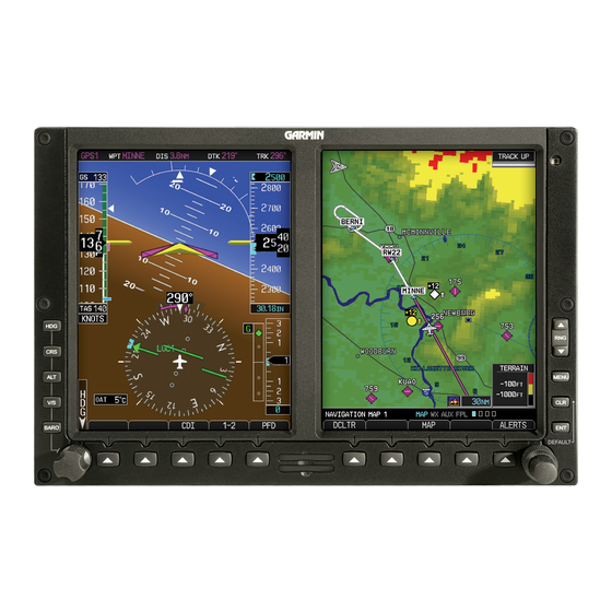
fl ight instrument cluster. The system combines primary fl ight instrumentation, navigational information, and a moving map all displayed on dual 6.5 inch color screens. The G500 system is composed of sub-units or Line Replaceable Units (LRUs). LRUs have a modular design and can be installed directly behind the instrument panel or in a separate avionics bay if desired. -
Page 12: Primary Flight Display (Pfd)
PRIMARY FLIGHT DISPLAY (PFD) Primary Flight Display (PFD) Primary Flight Display (PFD) G500 Cockpit Reference Guide 190-01102-03 Rev C... - Page 13 The indicator moves with the roll pointer and laterally away from the pointer to indicate lateral acceleration (slip/skid). Altitude Tape: Displays Current Altitude, Altitude Trend, Altitude Bug, Altitude Minimums Bug, and BARO setting. 190-01102-03 Rev C PRIMARY FLIGHT DISPLAY (PFD) G500 Cockpit Reference Guide...
-
Page 14: Airspeed Tape
If the current airspeed exceeds , the pointer changes to red with white text. Typical Airspeed Tape Markings Overspeed Overspeed Indication G500 Cockpit Reference Guide Current Airspeed Airspeed Tape Additional Reference Markings... -
Page 15: Altitude Tape
To change the BARO setting, press the BARO key and turn the PFD knob to the desired pressure. To select standard pressure (29.92 the PFD knob. 190-01102-03 Rev C PRIMARY FLIGHT DISPLAY (PFD) Altitude Bug Setting Current Altitude Altitude Tape G500 Cockpit Reference Guide ), press... -
Page 16: Barometric Minimums Bug
Alerting is inhibited while the aircraft is on the ground and also, if a value has been set for altitude alerting, until the aircraft reaches 150 feet above the setting for the alert. G500 Cockpit Reference Guide Bug and text Bug and text are... -
Page 17: Altitude Bug
200 feet of the Altitude Bug setting or when deviating beyond 200 feet of the bug. Within 1000 ft 190-01102-03 Rev C PRIMARY FLIGHT DISPLAY (PFD) MFD knob to exit the MINIMUMS box. Setting Altitude Bug Deviation of Within 200 ft +/- 200ft Altitude Bug Indications G500 Cockpit Reference Guide... -
Page 18: Wind Vectors
Field Vertical Speed (V/S) The Vertical Speed Tape and Vertical Speed Bug are displayed below the Altitude Tape. Vertical Speed Bug G500 Cockpit Reference Guide Wind Vector Display Current Vertical Speed Vertical Speed Bug Setting Vertical Speed 190-01102-03 Rev C... -
Page 19: Vertical Deviation Indicator (Vdi)
The Outside Air Temperature, as sensed from the temperature probe on the aircraft, is displayed to the left of the HSI. This temperature is used in calculating the true airspeed. 190-01102-03 Rev C PRIMARY FLIGHT DISPLAY (PFD) ILS Approach G500 Cockpit Reference Guide... -
Page 20: Attitude Indicator
Roll Scale Zero Pointer pointing towards the ground. Roll Pointer G500 Attitude Indicator with a Ground Pointer Confi guration in a Left Turn In an aircraft with an Attitude Indicator that has a Sky Pointer, the pointer below the roll scale shifts with the roll or bank angle of the aircraft to keep the Roll Pointer pointing towards the sky. -
Page 21: Horizontal Situation Indicator (Hsi): Aircraft Heading
If magnetic heading and GPS ground track are lost, a red “X” will appear in place of heading. 190-01102-03 Rev C PRIMARY FLIGHT DISPLAY (PFD) Roll Pointer Slip/Skid Indicator Slip/Skid Indicator Turn Rate Markings Heading Trend HSI Heading Markings G500 Cockpit Reference Guide... -
Page 22: Adjusting The Course Pointer
GPS source is available. Additionally, ADF is available if an ADF source is installed. NAV2 Bearing Pointer Selected source for BRG 1 bearing pointer Bearing Pointers on the HSI G500 Cockpit Reference Guide NAV1 Bearing Pointer Selected source for BRG 2 bearing pointer 190-01102-03 Rev C... -
Page 23: Gps Mode
OBS: Displays when OBS mode is activated. SUSP: Displays when automatic waypoint sequencing on the interfaced GPS unit is suspended. 190-01102-03 Rev C PRIMARY FLIGHT DISPLAY (PFD) GPS Mode Suspend SUSP PFD HSI Annunciations G500 Cockpit Reference Guide TERM LNAV LNAV+V LNAV/VNAV... - Page 24 NOTE: Verify the navigation source by the indication on the HSI. NOTE: The selected navigator is the active navigator for all the PFD and MFD operations, except for the supplemental bearing pointers. G500 Cockpit Reference Guide VLOC NAVIGATOR 1 VLOC...
-
Page 25: Autopilot (Ap)
Autopilot (AP) The G500 is able to interface to certain autopilot systems to provide heading, course, and navigation information in much the same way as a typical HSI indicator. Please refer to your particular autopilot manual for specifi c information and operation instructions. -
Page 26: Altitude Capture (Optional Interface)
Autopilot Navigation Set your navigation source and HSI to the desired course. Engage your autopilot in navigation mode. Control your autopilot navigation through the navigation source and the HSI. G500 Cockpit Reference Guide ALT key and 190-01102-03 Rev C... -
Page 27: Autopilot Operation With The Gdu 620 Emulating Gpss
HSI by the GPSS annunciation. The heading bug may still be used for reference but the autopilot will not control the aircraft on the heading bug. 190-01102-03 Rev C PRIMARY FLIGHT DISPLAY (PFD) GPSS Emulation Indication G500 Cockpit Reference Guide... -
Page 28: Additional Features
SVT are unavailable (generating a GDU DB ERR or SVT DISABLED alert) or AHRS or GPS data is unavailable. SVT may be restored once the fail conditions are removed by following the steps in “Displaying SVT Terrain”. G500 Cockpit Reference Guide ™ (Optional) Horizon... -
Page 29: Displaying Garmin Svt Terrain
The following features are part of the Synthetic Vision Technology. For more details refer to the G500 Pilot’ s Guide, Rev. C or later. • Flight Path Marker • Horizon Heading Marks • Terrain/Obstacle Display and Alerting • Three-dimensional Traffi c •... -
Page 30: Multi-Function Display (Mfd)
Menu: Displays confi guration items for each page of the page groups. Range Select: Changes the range on the map pages. Up arrow zooms out, down arrow zooms in. Also aids in scrolling up and down text pages. G500 Cockpit Reference Guide 190-01102-03 Rev C... -
Page 31: Page Navigation - Moving Between Pages
Default Map Page Press and hold the CLR key to return to the fi rst page of the MAP group. 190-01102-03 Rev C MULTI-FUNCTION DISPLAY (MFD) Turn Small MFD knob G500 Cockpit Reference Guide Page... -
Page 32: Mfd Soft Key Map
(Optional) TRAFFIC TOPO MODE TERRAIN TRAFFIC STANDBY OPERATE CONTROL ALT MODE TERRAIN PROXIMITY TERRAIN VERTICAL G500 Cockpit Reference Guide SYSTEM SETUP DFLT UNIT DFLT SPD XM INFO LOCK XM RADIO CHNL CH - CH + DIR CH BACK CATGRY STANDBY... -
Page 33: Map Group
INFO soft key (if available) to view more information about the highlighted waypoint. Press the WX soft key (if available) to view TAF and METAR information. Press the small MFD knob again to return to the map. 190-01102-03 Rev C Map Group G500 Cockpit Reference Guide MAP GROUP Map Pointer... -
Page 34: Decluttering (Dcltr) The Map Pages
Distance, Bearing and Coordinates Display Press ENT to reset the distance and bearing values. Press the small MFD knob to stop measuring. G500 Cockpit Reference Guide Measuring Map Pointer 190-01102-03 Rev C... - Page 35 NOTE: In the Map Options Setup section, the selected range is defi ned as the map range below which the display feature will be visible. 190-01102-03 Rev C Map Setup Option Menu Available Groups G500 Cockpit Reference Guide MAP GROUP MFD knob to...
- Page 36 Restricted (Range: Off to 500 • MOA (Military) (Range: Off to 500 • Other/Adiz (Range: Off to 500 • TFR (Range: Off to 2500 • Airways (Off, All, LO Only, HI Only) G500 Cockpit Reference Guide Selections 190-01102-03 Rev C...
-
Page 37: Traffi C Map Page (Optional)
The traffi c pop-up window will be removed when the traffi c alert is no longer active. Traffi c Traffi c Annunciation Traffi c Pop-Up PFD Traffi c Display MFD Traffi c Pop-Up Window G500 Cockpit Reference Guide 190-01102-03 Rev C... - Page 38 “TAS OPERATING” is displayed in the Traffi c mode fi eld located in the upper left hand corner of the MFD. Traffi c Mode Field G500 Cockpit Reference Guide Traffi c Map - TAS Altitude Mode Field...
- Page 39 MFD. After a few seconds, test mode is exited automatically by the traffi c system. Traffi c Annunciation on PFD 190-01102-03 Rev C Description Traffi c Annunciation G500 Cockpit Reference Guide MAP GROUP MENU...
- Page 40 NOTE: TIS is disabled when a Traffi c Advisory System (TAS) is installed. Operating Mode Traffi c Advisory, aircraft is 800 feet above, climbing, and moving away G500 Cockpit Reference Guide Traffi c Map - TIS 190-01102-03 Rev C Traffi c Advisory, aircraft is 1000 feet below and moving away...
-
Page 41: Terrain Page
Soft Keys Found on Terrain Page Garmin provides the following G500 TERRAIN selections, based upon your system confi guration. WARNING: Do not use TERRAIN-SVT information for primary terrain avoidance. TERRAIN-SVT is intended only to enhance situational awareness. NOTE: Terrain data is not displayed when the aircraft latitude is greater than 75°... - Page 42 While viewing the Terrain page of the Map Page Group, press the 360 or ARC soft keys to select the desired view. Press MENU for selections to hide or show Aviation Data Overlay on the Terrain page. G500 Cockpit Reference Guide 360 or ARC Soft Keys Aviation Data Overlay 190-01102-03 Rev C...
-
Page 43: Terrain Pop-Up Alerts
MFD. To acknowledge the pop-up alert and return to the currently viewed page, press the CLR key. To acknowledge the pop-up alert and go to the TERRAIN-SVT page, press the ENT key. G500 Cockpit Reference Guide 190-01102-03 Rev C... -
Page 44: Wx Group
MFD knob to set the preference of the weather feature option. Press ENT to confi rm your selection. To return to the WX Data Link Map page, press the small G500 Cockpit Reference Guide WX Group MFD knob. 190-01102-03 Rev C... - Page 45 Range: Off, 10 Range: Current, 12 HR to 48 HR Range: Off, 10 Range: Off, 10 Range: Surface, 3000 Range: Off, 10 On, Off G500 Cockpit Reference Guide WX GROUP to 2000 to 2000 to 2000 to 2000 to 2000...
-
Page 46: Displaying Surface Data And Winds Aloft
WINDS ALOFT DATA VIEWING RANGE, the WIND DOWN and WIND UP soft keys will be available. To view winds aloft, press the WIND DOWN or WIND UP soft keys to cycle through (up or down) the winds aloft altitudes. G500 Cockpit Reference Guide Mini-Legend 190-01102-03 Rev C... -
Page 47: Weather Radar (Optional)
WX GROUP Weather Radar (Optional) Weather Radar Map Page Soft Keys Found on Weather Radar Map Page Weather Radar G500 Cockpit Reference Guide 190-01102-03 Rev C... -
Page 48: Airborne Color Weather Radar
Monitor the displayed tilt value in the TILT fi eld. The range of tilting the antenna is DN 15° to UP 15°. Press the small MFD knob to confi rm selection. G500 Cockpit Reference Guide STANDBY soft key to initiate the 190-01102-03 Rev C... -
Page 49: Adjusting Gain
The line pointer is a reference depicting the calibrated position. Press the ENT key to remove the cursor. To restore the gain to the calibrated position, press the 190-01102-03 Rev C GAIN CAL soft key. G500 Cockpit Reference Guide WX GROUP... -
Page 50: Antenna Stabilization
Press the WATCH soft key again to deactivate. Automatic Standby When the weather radar system is in the Weather or Ground Map Mode, upon landing the system automatically switches to Standby Mode. G500 Cockpit Reference Guide CONTROL soft ™ 190-01102-03 Rev C... -
Page 51: Aux Group
V Speed References on Airspeed Tape NOTE: At any time during the setting of your airspeed references, pressing the DFLT SPD soft key will restore the unit to its initial confi guration. 190-01102-03 Rev C Aux Group Airspeed References G500 Cockpit Reference Guide AUX GROUP... - Page 52 ON or OFF. Press ENT to move to the DATE/TIME box or press the small MFD knob to exit the editing mode. G500 Cockpit Reference Guide Style 3 Synchronization Option Style 4 190-01102-03 Rev C...
-
Page 53: Setting Time Format
-5 hours Central -6 hours Mountain -7 hours Pacifi c -8 hours Alaskan -9 hours Hawaiian -10 hours 190-01102-03 Rev C -3 hours -4 hours -5 hours -6 hours -7 hours -8 hours -9 hours G500 Cockpit Reference Guide AUX GROUP... -
Page 54: Mfd Display Units
While viewing the System Setup Page of the Aux Page Group, press the small MFD knob and turn the large MFD knob to move to the desired fi eld of the SYSTEM DISPLAY UNITS box. G500 Cockpit Reference Guide 190-01102-03 Rev C... - Page 55 MFD knob to display your choices of CELSIUS(°C) or FAHRENHEIT(°F) for the temperature. Press ENT to confi rm your selection and press the small MFD knob to exit editing mode. 190-01102-03 Rev C G500 Cockpit Reference Guide AUX GROUP ) or...
-
Page 56: Xm ® Information Page (Optional)
MFD knob to display the XM Information screen. This page contains the Data Radio and Audio Radio IDs. The only option on this page is to LOCK in your information once your subscription has been activated. XM Information Page G500 Cockpit Reference Guide 190-01102-03 Rev C... -
Page 57: Xm ® Radio Page (Optional)
MFD knob to the category and press ENT. Turn the small MFD knob to move to the desired channel. Press ENT to make that channel the active channel. Press the small MFD to end editing. 190-01102-03 Rev C G500 Cockpit Reference Guide AUX GROUP... - Page 58 While viewing the XM Radio page, press the PRESETS soft key and press the preset soft key for the desired stored channel, such as PS1. To move to the next group of presets, press the MORE soft key. G500 Cockpit Reference Guide 190-01102-03 Rev C...
-
Page 59: System Status Page
DBASE soft key and turn the small MFD knob to view the list of the databases loaded into the GDU 620. Press the small MFD knob to exit. 190-01102-03 Rev C System Status Page G500 Cockpit Reference Guide AUX GROUP... -
Page 60: Flight Plan Group
fl ight plan. Press the INFO soft key to view information about the highlighted waypoint. Press the small MFD knob to return to the Active Flight Plan page. G500 Cockpit Reference Guide Active Flight Plan Page 190-01102-03 Rev C... -
Page 61: Waypoint Information Page
FPL, Nearest, and Recent. Press the INFO soft key to view information about the waypoint. Press the WX soft key (if available) to view weather information for the waypoint. 190-01102-03 Rev C G500 Cockpit Reference Guide FPL GROUP... -
Page 62: Charts Page (Optional)
MFD knob to move vertically. Press the small MFD knob to cancel the scroll bars and exit panning. NOTE: Panning mode is available when scroll bars are present. G500 Cockpit Reference Guide MENU key MFD knob to highlight the Display Level RNG (Range) -
Page 63: Viewing Notams
NOTE: The chart for the selected destination airport or approach is automatically loaded. If the destination airport is in the fl ight plan, the chart page will default to the nearest airport. 190-01102-03 Rev C Charts Page G500 Cockpit Reference Guide FPL GROUP SELECT soft... -
Page 64: Selecting Other Charts
MFD knob to show FPL, NRST, or RECENT. Turn the large MFD knob to highlight the desired airport, then press ENT. Display Charts From Flight Plan G500 Cockpit Reference Guide Display Charts Of Display Charts From Nearest Airport Recent Choices... -
Page 65: Chart Information
The ChartView database is updated on a 14-day cycle. ChartView is disabled 70 days after the expiration date and is no longer available for viewing upon reaching the disable date. 190-01102-03 Rev C G500 Cockpit Reference Guide FPL GROUP... -
Page 66: Alerts
ALERTS NOTE: Contact your Garmin dealer for service if any of the following alerts appear. On Screen Alerts Alert AHRS 1 not receiving any GPS information. AHRS1 GPS AHRS 1 is operating exclusively in no-GPS mode. AHRS 1 is using the backup GPS information. - Page 67 GDU has received product data for an LRU that should MANIFEST have a manifest entry, but is not in the manifest. NAV1/2 FAIL No navigation receiver #1 or #2 data. SIMULATOR Sim Mode is active. Do not use for navigation. 190-01102-03 Rev C Description G500 Cockpit Reference Guide ALERTS...
-
Page 68: Terrain-Svt ™ Alerts
FLTA Obstacle Caution FLTA Obstacle Warning * Alerts with multiple messages can be confi gured at installation and are installation- dependent. Alerts for the default confi guration are indicated with asterisks. G500 Cockpit Reference Guide Description “Terrain System Failure” “Caution, Terrain, Terrain”... -
Page 69: Symbols
Non-towered, Serviced Airport Towered, Serviced Airport Soft Surface, Serviced Airport Soft Surface, Non-serviced Airport Private Airport Heliport Intersection LOM (compass locator at outer marker) NDB (Non-directional Radio Beacon) VOR/DME ILS/DME or DME-only VORTAC TACAN G500 Cockpit Reference Guide 190-01102-03 Rev C... -
Page 70: Safetaxi ® Symbols
Traffi c Symbols Symbol Traffi c Advisory (TA), In Range Traffi c Advisory (TA), Out of Range Proximity Advisory (PA) Other Traffi c On-Ground Aircraft Ground Non-Aircraft Vehicle G500 Cockpit Reference Guide Description Description (Highest to Lowest Priority) 190-01102-03 Rev C... -
Page 71: Terrain Obstacle Symbols
Unlighted Obstacle Terrain between 100 ft and 1000 ft below the aircraft altitude (Yellow) Terrain more than 1000 ft below the aircraft altitude (Black) Description G500 Cockpit Reference Guide SYMBOLS Terrain above or within 100 ft below the aircraft altitude (Red) -
Page 72: Xm ® Weather Toolbar Symbols
SYMBOLS ® Weather Toolbar Symbols Symbol NEXRAD Echo Top Cloud Top XM Lightning Cell movement SIGMETs / AIRMETs METARs City Forecast Surface Analysis Freezing Levels Winds Aloft County Warnings Cyclone Warnings G500 Cockpit Reference Guide Description 190-01102-03 Rev C... -
Page 73: Miscellaneous Symbols
Default Aircraft (Ownship) High Wing Aircraft Jet Aircraft Default Map Pointer Elevation Map Pointer User Waypoint Parallel Track Waypoint TFR (Temporary Flight Restrictions) Restricted/Prohibited/Warning/Alert Class B Airspace Class C Airspace Class D Airspace G500 Cockpit Reference Guide 190-01102-03 Rev C... - Page 74 This page intentionally left blank G500 Cockpit Reference Guide 190-01102-03 Rev C...
- Page 76 © 2009 GARMIN Corporation GARMIN International, Inc. 1200 East 151 Street, Olathe, Kansas 66062, U.S.A. Tel. 913/397.8200 or 800/800.1020 Fax 913/397.8282 Garmin AT, Inc. 2345 Turner Rd., SE, Salem, Oregon 97302, U.S.A. Tel. 503/581.8101 or 800/525.6726 Fax. 503/364.2138 Garmin (Europe) Ltd.