Table of Contents
Advertisement
Save This Manual
For Future Reference
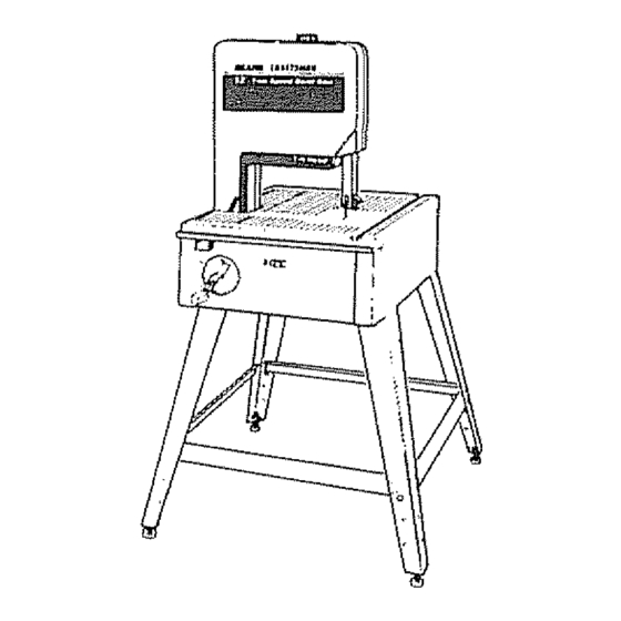
Model No.
1t 3,248212
Single
Speed
Band
Saw
with
Leg Set
Nlodel No.
113.248322
Two Speed
Band
Saw
with
Leg Set
Serial
Number
Model
and
serial
numbers
may
be found
at the
left-
hand side
of the base,.
You
should
record
both
model
and serial
number
in
a safe place for future use.
FO
YOU
SAFETY
\
READ ALL
iNSTRUCTiONS
CAREFULLY
Part No..SP5779
113.248212
113_248322
12 BNCH BA
o assembBy
o operating
o repair parts
SAW
.J
Sears,
Roebuck
and
Co.,
Hoffman
Estates,
IL. 60179
U.S.A.
.J
Printed in US A
Advertisement
Table of Contents

Related Manuals for Craftsman 113.248212


Summary of Contents for Craftsman 113.248212
- Page 1 Save This Manual For Future Reference Model No. 1t 3,248212 113.248212 Single Speed Band with Leg Set Nlodel No. 113.248322 Two Speed Band 113_248322 with Leg Set Serial Number Model serial numbers be found at the left- 12 BNCH BA hand side of the base,.
-
Page 2: Table Of Contents
FULLONE YEAR WARRANTY ON CRAFTSMAN BAND SAW If within one year from the date of purchase, this Craftsman Saw fails due to a defect in material or workmanship, Searswillrepairit, free ofcharge. WARRANTYSERVICEtS AVAILABLE BYSIMPLYCONTACTING THE NEARESTSEARSSERVICE CENTER/DEPARTMENT T HROUGHOUT THE UNITEDSTATES. - Page 3 WHEN INSTALLING OR MOVING THE SAW broken pads, stable mounting, and AVOID DANGEROUS ENVIRONMENT. Use the saw in a dry, indoor place protected from rain Keepwork area • any other conditions that may affect the way the saw well lighted works To avoid injury from unexpected saw movement:...
- Page 4 Plan ahead to protect your eyes, hands, face Any power saw can throw foreign objects into the eyes.. This can cause perrnanent eye damage. Wear safety and ears. goggles (not glasses) that comply with ANSI Z871 KNOW YOUR SAW. Read and understand the owner's (shown on package) Everyday eyeglasses...
- Page 5 • Cleareverything except t he workpiece andrelated Before freeing any jammed material: support d evices offthetablebefore turning thesaw , Turn switch "OFF" Plan the way you will hold the workpiece from start Remove switch key to finish, • Unplug the saw Do not hand hold pieces so small that your fingerswiil go •...
- Page 6 gtossary of terms for woodworking Both ModeUs Beveling Push Stick An angle cutting operation made through the face of the A device used to feed the workpiece through the saw dur- workpiece._ ing narrow ripping type operations and helps keep the Compound Cutting operator's hands well away from the blade.
- Page 7 This power tool is equipped with a 3-conductor cord and 2, If the motor fails to start, turn the power switch to the ground type plug listed by Underwriters' Laboratories., "OFF" position immediately Unplug the tool,, Check the The ground conductor has a green jacket and is attached sawblade to make sure it turns freely If the blade is to the tool housing at one end and to the ground prong in...
-
Page 8: General Information
genera information BOTH MODELS 1, This manual is for the following models - 113.2482t2 Model Description and 113248322. All sections are labeled with the cor- Model 113.248212; Manual Band Saw; 18 x 23 inch work rect model number: Follow ONLY instructions that are table;... - Page 9 TABLE OF LOOSE PARTS ITEM DESCRIPTION QTY., Motor ....... Pulley ......... Loose Parts Bag Basic Saw Assembly ....Owners Manual ....containing the following items: Band Saw Blade 1/4 x 80 ..Trim Cap, L H ....Sanding Belt 1/2 x 80 Trim Cap, R H ......
- Page 10 BOTH MODELS LIST OF LOOSE PARTS IN BAG DESCRIPTION QTY. ITEM Truss Head Screw 1/4-20 x 12 ....Lockwasher, External 1/4 .... Hex Nut 1/4 -20 ..Leveling Foot ..Hex Jam Nut 3/8-16 ....Bracket Leg .... LIST OF LOOSE PARTS IN BAG ITEM...
- Page 11 assembay and aSignntent BOTH MODELS ATTACHING LEVELING FEET From the loose parts bag find tf_e 1ollowing hardware: ITEM DESCRIPTION QTY. Support Brackel ......Leveling Feet ..Hex Nut318-16 ..From the loose parts find the following items: ..® ® 1 Mount floor leveler support brackets inside legs, Line up the three tabs on brackets with slots on leg ®...
- Page 12 BeTH MODELS ATTACHING LEG SET ¢ From the loose parts bag find the following hardware: Item Description Qty,, Truss Head Bolts 1,/4-20 x I/2 Lockwashers External V4 Hex Nuts V4-20 ..From the loose parts find the following items: Leg Channel Legs (with attached support brackets and leveling feet) Lower Stiffeners...
-
Page 13: Adjusting Leveling Feet
5 Usetrusshead bolts,tockwashers, andhexnutsto mount t hetwo(2) rear legs to the basic saw assem- bly It may be necessary to slightly tilt the saw as- sembly backwards in order to get the four (4) holes in each corner of the saw to line up with the four (4) holes in the top of each leg Finger tighten nuts at this time 6 Attach the four (4) lower stiffeners to the legs Two (2) -
Page 14: Mounting The Motor
BOTH MODELS MOUNTING THE MOTOR A-,t- 1, Find the following parts: ITEM DESCRIPTION QTY. Motor ................1 Spacer (#10 x 1/4) ..........3 Flanged Locknut #10-32 ..........Wing Nut 5/16-18 ............. Motor Pulley w/Set Screw (Model ! 13,,248322) ............ Belt Tension Stud ............1 Motor Pulley w/Set Screw (Model 113248212 ........ - Page 15 BOTH M@@EL 5,, Place the Poly "V" belt into the motor mount as shown on the underside of the band saw 6 Look atthe motor mount and find the slot that is nar- MOTOR MOUNT rower than the other three. When mounting the motor, the motor stud without a spacer goes into this slot.
- Page 16 MOTOR MOUNT BOTH MODELS 10 Install a flanged lock nut onto this motor stud Tighten the flanged lock nuts, using a 3/8-inch wrench, until almost tight, It will be easier to tighten lock nuts if the head is tilted to approximately 45 °...
-
Page 17: Connecting The Motor
CONNECTING MOTOR 1 Next, the motor cord needs to be wired into the motor Coming from the underside of the table will be a cord TERMINAL with a black, white and green wire This is the motor GREEN cord_ i WARNING: Foryourown safety, neverplug saw in until all assembly steps are completed,. -
Page 18: Selecting Blade Speed
MODEL 113.248322 ONLY SELECTING BLADE SPEED The band saw has two speed settings: 3000 FPM for nor- real operation and 1500 FPM for-operation requiring more control of the workpiece MOTOR 1500 3000 CAUTION: Model 113.248322 is NOT designed RECOMMENDED SPEED SETTINGS cutting or' sanding ferrous metals like iron or steel. -
Page 19: Getting To Know Your Band Saw
getting to know your band saw B@YH M@D L$ 1. Warning Label 2, Tensions Adjustment Knob - Tightening the knob will increase the tension on the blade Loosening it will decrease the tension Clockwise to tension, counterclockwise to toosen 3o Setting Bevel Angle - Pull the bevel lock knob and adjust he band saw to the desired angle by turning the GUIDE BAR handwheel, then push in the bevel lock to secure... -
Page 20: Installing The Blade
BOTH MQDIEm=S iNSTALLING THE BLADE GUARD ing, make sure the power cord is unplugged MOUNTING I WARNING: To avoid injury from accidental start- I SCREW before removing any part from the saw. 1,, Remove the blade guard by loosening the two (2) mounting screws with a phillips screwdriver and lifting the blade guard upward,_ JARD... - Page 21 uPPE.BLAOE GU,O SUPPORT il Z. 4 Loosen the setscrew which locks the blade guide support and push the support all the way back SETSOR W Repeat for lower blade guide support LOWER BLADE GUIDE SUPPORT =°_ SETSCREW 5 Loosen the setscrew which locks the upper back UPPER BACKUP up bearing...
-
Page 22: Aligning The Blade And Blade Guide Assemblies
BOTH MODELS ALIGNING THE BLADE AND BLADE G UIDE ASSEMBLIES This band saw comes equipped with a 1!4-inch blade, This band saw can be used with blades of width from 1/8qnch to 1/2-inch. The alignment steps must be followed for proper tension, blade guide, and bearing adjustments for each different blade. - Page 23 3 The upper lower blade guides support blade and keep it from twisting during operation Adjust blade guide support whenever blades changed or replaced with a different width 4 Push the blade guide support toward the blade adjust the blade guides so they are about...
-
Page 24: Mounting The Front Table
60TH MODELS FRONT COVER Install the front cover Rest top edge of cover on two latch springs atong the top edge of back cover- Swing cover down into position, engaging the three other-latch springs Push the front LATCH cover into position on the back cover Check that SPRING the tip on the front Cover-completely overlaps the... - Page 25 TABLE LATCH LARGE 4, Locate the two (2) table latches, two (2) 3ie"long Phil- WASHER ON RIGHT lips head self tapping screws, two(2) smail washers, SlOE ONLY and one (1) iarge washer SMALL 5 Piace front table latch through slot on right side ot WASHER bandsaw frame t TABLE...
-
Page 26: Squaring The Blade To The Table
BOTH MODELS SQUARING THE BLADE TO THE TABLE 0 sTo,.,..,w WARNING: To avoid Injury from unexpected| starting, make sure power cord Is unplugged before making adjustments to band saw parts, COMBINATION To assure repeatability and accuracy, it is important J i: SQUARE to square the blade to the table and adjust the 0 °... -
Page 27: On-Off Switch
location and function of controts BOTH MODELS ON-OFF SWITCH NOTE: The On-Off switch has a locking feature, This feature is intended to help prevent unauthorized possibly hazardous use by children and others, ....1=,Insert yellow key into switch 2.. To turn on, insert finger under end of red switch lever and pull end out., 3. - Page 28 basUcband saw operation MAINTAIN TOOLS WITH CARE Keep the saw clean BEFORE USING THE SAW: for best and safest performance Follow instructions for WARNING: To avoid mistakes that could cause lubricating. serious, permanent injury, do not plug the saw in until the following steps are completed.
- Page 29 To avoid injury from accidental contact with moving pars, damage, wear ear plugs or muffs when using saw for don't do layout, assembly, or set up work on the saw hours at a time while any parts are moving ° For dusty operations, wear a dust mask along with the safety goggles AVOID ACCIDENTAL STARTING,...
- Page 30 Avoid awkward operations a ndhandpositions w here • Wait for all moving parts to stop asudden slipcould cause fingers o rhand tomove into thebladeor sanding surface When backing up the workpiece, the blade may bind in the kerr (cut). This is usually caused by sawdust DON'T OVERREACH Keep good footing and bal- clog ging up the kerr o r because the blade comes out...
-
Page 31: Circle Cutting
Mitering 1/4, 3/8, 1/2 Beveling 1/4, 3/8, 1/2 Your Craftsman Band Saw is not only capable of the Compound Cutting 1/4, 3/8, 1/2 usual band saw operations, but it can be converted into a sander as welt You can finish wood, certain... -
Page 32: Installing Sanding Attachment
B@'2'I M@@ELS INSTALLING SANDING ATTACHMENT WARNING: To avoid injury from unexpected starting, make sure power cord is unplugged before making adjustments to band saw parts. UPPER BACKUP NOTE: Tile sanding belt cuts very rapidly Practice with some scraps of wood first before you attempt to sand your actual workpiece _.NG SETSCREW... -
Page 33: Blade Guides
iNSTALLING 1/16 INCH BLADE AND BLADE GUIDE (Optional Accessory) WARNING: To avoid injury from unexpected starting, make sure power cord ts unplugged FRONT COVER before making adjustments to band saw parts, ,"BLADE GUARD BLADE FRONT TABLE 1 To install the 1/16+inch blade and non-metallic blade guides, lirst turn the switch off, remove the safety key, and unplug the saw, Remove the front table, front... - Page 34 B@TH M@@ELS BACKUP BEARING 6 lnslall the special non-metallic blade guides supplied wilh the 1!16-inch blade as shown. Separate these guides as far as they will go BLADE GUIDE BLADE GUIDE NON-METALLIC NON-METALLIC SEPERATE GUIDES AS FAR AS POSSIBLE 7 Uncoi! the 1/i 6-inch blade and place over the wheels with the teeth facing front of saw and pointing down towards the table, WARNING:...
-
Page 35: Scrolling
NOTE: Because of manufacturing tolerances in band saws and blades, it may be difficult to track the blade in the center of the wheel The blade may exhibit a tendency to wander to the front of the wheel,, If this condition exists, track the blade on the back hall of the BLADE ON BACK... -
Page 36: Accessories
Do not allow filth to build up on the table the guides or the motor mount The capscrews are located in the the back-up bearings. Clean them with Craftsman recessed area behind the hub of the lower wheel at Gum and Pitch Remover. the 2 oclock, 6 o'clock, and t0 o'clock positions... - Page 37 Light Bulb To replace the light bulb remove the front cover° Use a WIRE CONNECTOR phillips screwdriver to remove the lens and replace the _.3REQ)-_ BLACK bulb. The light butb is a 25 watt bayonet mount bulb. SWITCH ,,-- LAMP CORD Frequently blow or vacuum out any sawdust from the ..
-
Page 38: Trouble Shooting--Motor
trouble shooting--motor BOTH M@#ELS NOTE: Motors used on wood-working tools are particularly susceptible to the accumulation of sawdust and wood chips and should be blown out or "vacuumed" frequently to prevent interference with normal motor ventilation and proper operation of the centrifugally-operated starting switch TROUBLE PROBABLE CAUSE... - Page 39 notes...
- Page 41 PARTS LIST FOR CRAFTSMAN 12-INCH BAND SAW MODEL NO'S. 1'I 3.248212 & 113.248322 Always order by Part Number - Not by Key Number FIGURE 1 - DRIVE ASSEMBLY PARTS Part No. Description Part No, Description '_ 30"816380 Lens 823672 Cover, Front!Scale 9-26595 1"...
- Page 42 PARTS LIST FOR CRAFTSMAN 12-INCH BAND SAWS MODEL NO'S. 113.248212 & 113.218322 .,.jl I""" FIGURE 2...
- Page 43 PARTS LIST FOR CRAFTSMAN 12-INCH BAND SAWS MODEL NO'S. 113.2482'I 2 & 113,218322 Always order by Part Number - Not by Key Number FIGURE 2- BASE COMPONENTS Part Noo Description Part No. Description 1 816421 Table, Rear 816434 Table, Front...
- Page 44 PARTS LIST FOR CRAFTSMAN 12-INCH BAND SAWS MODEL NO'S. 113.248212 & 113.218322 i°-'" FIGURE 3...
- Page 45 PARTS LIST FOR CRAFTSMAN 12-INCH BAND SAW MODEL NO'S. 113.248212 & 113.248322 Always order by Part Number - Not by Key Number FIGURE BEVEL DRIVE MOTOR MOUNT ASSEMBLY PARTS Part No. Description Part No, Description 816499 816465 Handwheel Assembly Spacer, 1/2 x .59...
- Page 46 PARTS LIST FOR CRAFTSMAN 12-INCH BAND SAWS MODEL NO'S. 113.248212 & 113.218322 Always order by Part Number - Not by Key Number FIGURE 4 - LEG SET PARTS LIST Part Description 81710'5 8181 63 Channel, Leg 815909 Stiffener, Lower 818170...
- Page 47 notes...
- Page 48 ,,.._ .........._ (.-- ..........12 iNCH Now that you have purchased your 12 inch Band Saw, should a SERVICE need ever' exist for repair parts or service simply contact any Sears Service Center and most Sears, Roebuck and Co stores.