Table of Contents
Advertisement
f
Save This Manual
For Future Reference
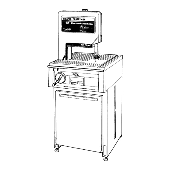
SEARS
owners
monuol
MODEL NO.
113.247410
ELECTRONIC BAND SAW
WITH CABINET & DOOR
S_rial
Number
Model and s_rial nunnb_rs
may b_ found
at the
I_t-hand
side of the bas_.
You should record both
model and s_rial number
in a safe place
for future
US_.
CAUTION:
READALL
INSTRUCTIONS
CAREFULLY
CRRFTSMRN
12-1NCH ELECTRONIC
BAND SAW
• assembly
• operating
• repair pads
J
Sold by SEARS, R OEBUCKAND CO., Chicago, IL.60684 U.SA.
Part No. SP5085
Advertisement
Table of Contents

Related Manuals for Craftsman 113.247410


Summary of Contents for Craftsman 113.247410
- Page 1 Save This Manual For Future Reference SEARS owners monuol MODEL NO. 113.247410 ELECTRONIC BAND SAW WITH CABINET & DOOR S_rial CRRFTSMRN Number Model and s_rial nunnb_rs may b_ found at the I_t-hand side of the bas_. You should record both model and s_rial number 12-1NCH ELECTRONIC in a safe place...
- Page 2 FULL ONE YEAR WARRANTY ON CRAFTSMAN BAND SAW If within one year from the date ol purchase, this Craftsman Band Saw fails due to a defect in material or workmanship, Sears will repair it, free of charge. WARRANTY SERVICE IS AVAILABLE...
-
Page 3: Additional Safety Instructions For Band Saw
additional safety instructions for band saw Safety is a combination of common sense, staying and lock knob, lower blade guide, tension adjust- alert, and knowing how your band saw works. ing knob and tension scale, and blade thrust bearing adjustment. BEFORE USING THE SAW: 3. -
Page 4: Before Sanding
additional safety instructions f. To avoid being suddenly caught in the blade: WHENEVER IS RUNNING 1. Do not wear gloves. WARNING: ALLOW FAMILIARITY 2. Remove all jewelry and loose clothing. (GAINED FROM FREQUENT OF YOUR BAND SAW) CAUSE A CARELESS MIS- 3. - Page 5 table of contents Page Page General Safety Instructions for Power Tools ..Getting to Know Your Band Saw ....Location and Function of the Electronic Additional Safety Instructions for Band Saw ..Before Using the Saw ......Indicator System ......When Installing or Moving the Saw ....
-
Page 6: Power Supply
electrical connections WARNING: TO MAINTAIN PROPER TOOL GROUND- ING WHENEVER THE OUTLET YOU ARE PLAN- POWER SUPPLY NING TO USE FOR THIS POWER TOOL IS OF THE TWO PRONG TYPE, DO NOT REMOVE OR ALTER Motor Specifications THE GROUNDING PRONG IN ANY MANNER. USE The AC motor used in this saw is a capacitor-start, AN ADAPTER AS SHOWN... -
Page 7: Wire Sizes
LOW VOLTAGE - Although the motor is de- overheating and motor burn-out, use the table below signed for operation on the voltage and fre- to determine the minimum wire size (A.W.G.) exten- quency specified on the motor nameplate, sion cord. Use only 3-wire extension cords which normal loads will be handled safely on voltages have... - Page 8 unpacking and checking contents TABLE OF LOOSE PARTS |el 113.247410 Electronic Band Saw comes com- e in one carton and includes a cabinet with a sr shelf and door. ITEM DESCRIPTION QTY. Motor. Basic S ';w'_;,em_)i_: :: :::: :: ..•...
- Page 9 LIST OF LOOSE PARTS IN BAG #507656 ITEM DESCRIPTION QTY. A Truss Head Screw 1/4-20 x 1/2 ..Lockwasher Ext. 1/4 ....Hex Nut 1/4-20 ......Leveling Foot ......E Hex Jam Nut 3/8-16 ....R Cover ......... LIST OF LOOSE PARTS IN BAG #507655 ITEM...
-
Page 10: Assembly And Alignment
assembly and alignment ASSEMBLING CABINET 1. Separate all "loose" parts from packing materials and check each item with "Parts List" to make sure all items are accounted for before discard- ing any packing material. From loose parts find the following items: ITEM DESCRIPTION... - Page 11 SKIRT RIGHT SIDE PANEL 5. Locate the two (2) skirts, eight (8) truss head bolts, Iockwashers and hex nuts. Assemble one (1) skirt to the front of the cabinet through the holes as illustrated. Stand the cabinet upright and assemble the rear skirt.
-
Page 12: Mounting The Motor
MOUNTING THE MOTOR 1. Find the following parts: ITEM DESCRIPTION QTY. AA Motor ......... J Spacer (1/40.D. x 5/16) ....Flanged Locknut #10-32 ....M Wing Nut 5/16-18 ...... Belt Tension Stud ..... W Motor Pulleyw/Setscrew ....Poly"V" Belt ......X Shaft Key 3/16 ...... - Page 13 SPACE. ) 7. Carefully position the motor so that the poly "V" belt is around motor pulley four motor studs align with slots in the motor mount. 8. Push motor studs through and install the flanged lock nuts to the three motor studs...
-
Page 14: Selecting Blade Speed
14. Belt tensioning is done by tightening the wing nut which pulls the motor down. The motor slides on the three (3) spacers and is locked in place by the flanged lock nut at the threaded stud. Belt tension is important. Over tensioning cause vibration while too little tension may allow the belt to slip under heavy loads. -
Page 15: Connecting The Motor
CONNECTING THE MOTOR 1. Next, the motor cord needs to be wired into the motor. Coming from the underside of the table will be a cord with a black, white and green wire. TERMINAL This is the motor cord. GREEN WARNING: FOR YOUR OWN SAFETY, NEVER PLUG THE SAW IN UNTIL... -
Page 16: Mounting Door
2. Place saw on cabinet so that holes in bottom of saw line up with holes in top of cabinet. 3. Install bolts, Iockwashers, and nuts as shown. Tighten securely using a 7/16-inch wrench socket. The front two bolts hold the saw, lower wheel cover, and the cabinet together. -
Page 17: Attaching Trim Caps And Trim Ledge
ATTACHING TRIM CAPS & TRIM LEDGE 1. Locate the two (2) trim caps, the trim ledge, and from loose parts bag six (6) screws 1/4 x 1/2. 2. Place the trim ledge against the bottom of the base, then reach through the base and secure the trim ledge with the two screws using a phillips PHI LLIPS SCREWDRIVER... -
Page 18: Getting To Know Your Band Saw
getting to know your band saw WARNING LABEL TENSION ADJUSTMENT KNOB COVER CRRFTSNRN WARNING GUIDE BAR LABEL LOCK KNOB BLADE GUIDES MITER GAGE SLOT 3EVEL LOCK KNOB BEARING BLADE GUIDES HANDWHEEL ON-OFF SWITCH BLADE GUIDES ELECTRONIC/INDICATOR SYSTEM BACK-UP BEARING GETTING TO KNOW YOUR BAND SAW 6. -
Page 19: Location And Function Of The Electronic Indicator System
location and function of the electronic indicator system BATTERY COVER RELEASE SLOTS BATTERY COVER ON/OFF • OPEN BATTERY OPEN • BEVEL ANGLE KEY ELECTRONIC MEASUREMENT BLADE TENSION KEY (FT. PER MIN.) REFERENCE SET KEY DIGITAL READOUT DISPLAY FUNCTION KEYS DIGITAL READOUT DISPLAY The five keys located to the right of the display are... - Page 20 USING ELECTRONIC INDICATOR SYSTEM 1. Setting the Bevel Angle Reference Point. 3. Blade Speed Whenever the battery is installed or a new zero The digital display will read out one of two point is desired, it is necessary to set the zero starting speeds, depending on where the motor...
-
Page 21: Installing The Blade
INSTALLING THE BLADE 1. Remove the blade guard by loosening the two (2) _UGA RO mounting screws with a phillips screwdriver lifting the blade guard upward. BLADE GUARD " II__-_-._ MOUNTING 2. Loosen the upper blade guide assembly lower to approximately 3 inches above rear table and retighten lock knob. - Page 22 UPPER BACKUP 5. Loosen the setscrew which locks the upper back up bearing and push the bearing all the way back. Repeat procedure for lower back up bear- ing. BEARING SETSCREW CAUTION: To avoid being scraped, if the blade BLADE CENTERED RUBBER TIRE...
- Page 23 2. Turn the upper wheel by hand a few times and notice if the blade remains in the center of the ti re on the top wheel. TRACKING ADJUSTMENT SCREW If the blade moves away from the center of the tire while you are turning it, the blade is not...
- Page 24 6. To insure the backup bearing is properly sup- °"°EI porting the blade, push the bearing toward the BACKUP BEARING blade until it almost touches it. Turn the upper BACKUP BEARING wheel, by hand, checking the backup bearing to SETSCREW make sure it is not turning.
- Page 25 HEAD 4. Locate the two (2) table latches, two (2) pan head SCR EW screws, Iockwashers, and hex nuts. Install table latches to the underside of the front of the base in holes provided. FRONT TABLE LATCH LOCKWASHE XNUT _...__ 1/4-20X OW HEAD CAPSCREW...
- Page 26 8. To keep the miter gage grooves in line, use a flat blade screwdriver against the head of one of the low head capscrews in the miter gage groove to force the table alignment key firmly forward into the notch in the front table. 9.
-
Page 27: Location And Function Of Controls
location and function of controls ON-OFF SWITCH NOTE: The On-Off switch has a locking feature. This feature is intended to help prevent unauthorized possibly hazardous use by children and others. 1. Insert yellow key into switch. ") _-- 2. To turn on, insert finger under end of red switch lever and pull end out. -
Page 28: Basic Band Saw Operation
Mitering 1/4, 3/8, 1/2 is not capable of doing inside cutting. Beveling 1/4, 3/8, 1/2 Your Craftsman Band Saw is not only capable of the Compound Cutting 1/4, 3/8, 1/2 usual band saw operations, but it can be converted... -
Page 29: Sawdust Collection
SAWDUST COLLECTION 1. There is an opening provided in the rear of the bottom cover to attach a 2-1/2-inch hose from a wet/dry vac to control sawdust. COLLECTION OPENING INSTALLING SANDING ATTACHMENT UPPER BACKUP NOTE: The sanding belt cuts very rapidly. Practice with some scraps of wood first before you attempt... -
Page 30: Recommended Accessories
INSTALLING THE SANDING BELT Install the sanding belt and adjust tension to the sanding position. (The letter "S" on the scale.) NOTE: Check the tension often when a new belt is installed. A new belt will stretch during use. Rotate the upper wheel by hand (clockwise) check the sanding belt tracking. -
Page 31: Maintenance
Do not allow filth to build up on the table, the guides ADJUSTING BAND SAW BEVEL TRAVEL or the back-up bearings. Clean them with Craftsman Gum and Pitch Remover. If the band saw will not hold its position when at a... -
Page 32: Trouble Shooting
trouble shooting WARNING: FOR YOUR OWN SAFETY, TURN SWITCH "OFF" AND REMOVE PLUG FROM POWER SOURCE OUTLET BEFORE TROUBLE SHOOTING YOUR BAND SAW/SANDER. TROUBLE PROBABLE CAUSE REMEDY Blade does not run in 1. Not tracking properly. 1. Adjust tracking, see Assembly Section, the approximate center "Installing... - Page 33 trouble shooting -- motor NOTE: Motors used on wood-working tools are particularly susceptible to the accumulation of sawdust and wood chips and should be blown out or "vacuumed" frequently to prevent interference with normal motor ventilation and proper operation of the centrifugally-operated starting switch.
- Page 34 trouble shooting -- electronics SUGGESTED CORRECTIVE ACTION PROBABLE CAUSE PROBLEM - Adjust battery position in compartment. No display when Battery incorrectly - Install battery. is pressed. installed or missing. - Clean battery contacts. 2. Battery contacts dirty or corroded, - Replace battery. Battery is 6 volt, size J, 3.
- Page 35 trouble shooting -- electronics SUGGESTED CORRECTIVE ACTION PROBABLE CAUSE PROBLEM - Select FPM function. 1. Wrong display Display does not function selected. change when blade speed is changed. - Have electronics checked by qualified 2. Encoder or digital technician. Repair service available at nearest display defective.
- Page 36 PARTS LIST FOR CRAFTSMAN 12-INCH ELECTRONIC BAND SAW MODEL 113.247410...
- Page 37 PARTS LIST CRAFTSMAN 12-INCH ELECTRONIC BAND MODEL 113.247410 Always order by Part Number - Not by Key Number FIGURE 1 - DRIVE ASSEMBLY PARTS Part iKey Part Description Description 507830 Cover, Front w/Label Trunnion 816352 9-26595 tBlade, Band Saw Screw, Hex Wash Hd.
- Page 38 PARTS LIST FOR CRAFTSMAN 12-INCH ELECTRONIC BAND SAW MOD EL 113.247410 [_-----38 _--17 • _7 r _ REAR VIEW ELECTRONIC CONTROL PANEL...
- Page 39 PARTS LIST FOR CRAFTSMAN 12-INCH ELECTRONIC BAND MODEL 113.247410 Always order by Part Number - Not by Key Number FIGURE 2 - BASE COMPONENTS Part Part Description Description 815881 Cap, Trim R.H. 816434 Table, Front 507749 Trim, Ledge w/Label 806O36-2...
- Page 40 PARTS LIST FOR CRAFTSMAN 12-1NCH ELECTRONIC BAND SAW MODEL 113.247410...
- Page 41 PARTS LIST FOR CRAFTSMAN 12-INCH ELECTRONIC BAND MODEL 113.247410 Always order by Part Number - Not by Key Number FIGURE 3 - BEVEL DRIVE MOTOR MOUNT ASSEMBLY PARTS Part Description Description STD541110 816499 *Nut, Hex 10-32 Handwheel Assembly 1816504 816386...
- Page 42 PARTS LIST FOR CRAFTSMAN 12-1NCH ELECTRONIC BAND SAW MODEL NO. 113,247410 19 17 _ FIGURE 4 - PARTS LIST 23" CABINET Always order by Part Number- Not by Key Number Part Part Description Description 13 817150 Panel Side L.H. 805589-5 Screw, Truss Hd.
- Page 43 NOTES...
-
Page 44: Repair Parts
12-INCH ELECTRONIC owners BAND SAW manual SERVICE Now that you have purchased your 12-Inch Electronic Band Saw, should a need ¢,ver exist for repair parts or s_rvice, simply contact any S_ars Service Center and most S_ars, Rc_zbuck and Co. stores. Be sure to provide all pertinent facts when you call or visit.