Table of Contents
Advertisement
f
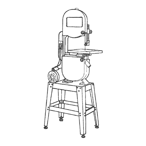
Save This Manual
For Future Reference
ModeJ No.
113.248340
Single
Speed
Band
Saw
with
Leg Set
Serial
Number
Model
and
serial
numbers
may be found at the rear of
the base.
You
should
record
both
model
and serial
number
in
a safe place for future use.
FOR YOU
SAFETY
READ ALL
INSTRUCTmONS
CAREFULLY
14 iNCH
D SAW
• assembly
• operating
, repair parts
1\
Sold
by SEARS,
ROEBUCK
AND CO.,
Hoffman
Estates,
IL. 60179
U.S.A.
Part No. SP5836
Y
Printed
in Taiwan
Advertisement
Table of Contents

Related Manuals for Craftsman 113.248340


Summary of Contents for Craftsman 113.248340
- Page 1 Save This Manual For Future Reference ModeJ No. 113.248340 Single Speed Band with Leg Set Serial Number Model serial numbers may be found at the rear of D SAW 14 iNCH the base. should record both model and serial number a safe place for future use.
-
Page 2: Warranty
FULL ONE YEAR WARRANTY ON CRAFTSMAN BAND SAW If within one year from the date of purchase, this Craftsman Band Saw fails due to a defect in material or workmanship, Sears wi|I repair it, free of charge. WARRANTY SERVICE IS AVAILABLE... -
Page 3: Dress For Safety
To avoid injury from jams, slips or thrown pieces Dress for safety broken blades. Any power saw can throw foreign objects into the ey'es. Inspect your blade. This can cause permanent eye damage. Wear safety ,' Choose the right blade size, style and cutting speed for goggles (not... -
Page 4: Before Leaving The Saw
Safety instructions for Band Saws (continued) ..o Wait for all moving parts to stop. Whenever Sawbiade is Spinning: - Remove switch key. When backing up the workpiece, the blade may bind quent use of your band saw) cause a careless mis- in the kerr (cut). -
Page 5: Power Supply And Motor Specifications
Motor Specifications and Electrical Requirements Have a qualified electrician replace the two prong outlet Power Supply and Motor Specifications with a property grounded three prong outlet. The A-C motor used in this saw is non-reversible type, hav- An adapter as shown is available for connecting the plug ing the following specifications: to a 2 prong receptacle. - Page 6 Motor Specifications and Electrical Requirements (continued) Wire Sizes CAUTION: For circuits that farther away from electrical service box, wire size must be I The use of any extension cord will cause some loss of power. To keep this to a minimum and to prevent over- increased proportionately in order...
-
Page 7: Unpacking And Checking Contents
Unpacking and Checking Contents Tools Needed Tools required for assembly and alignment: o Combination Square • 10ram and 14mm combination wrench Adjustable wrench. • #1 and #2 Phillips screwdrivers Combination Square o Straightedge Combination Square Must be True lOmm Combination Wrench Straight Edge of Draw Light... -
Page 8: Table Of Loose Parts
Unpacking and Checking Contents (continued) Table of Loose Parts Item Qescription Qty. Item Description Qty. Owners Manual ........... Cover Pulley ............V-Belt ..............Motor w/Switch ........... Band Saw ............Bag Asm ............. Table Asrn ............Leg ..............Trunnion Support ..........Stiffener (Long) ........... -
Page 9: List Of Loose Parts In Bag
List of Loose Parts in Bag totem Description Screw Pan Head M5 x 0.8-12 ......Washer Flat M5 x 10 Dia. Nut Hex Head M5 ....Bolt Hex Head M8 x 1.25-35 ......Washer Flat M8 x 18 Rubber Grommet ..........Washer Lock M8 .......... -
Page 10: Assembly
Assembly ..Attaching Leveling Feet 1_ From the loose parts find the following items: Item Description Qty. Levelingfeet ............Hex nut 3/8-16 ............ From the loose parts find the following items: Leg..............2. Put a hex nut on each of the leveling feet and screw it down towards the rubber foot. -
Page 11: Adjusting Leveling Feet
4. Turn assembly over onto the legs. Be sure all four feet sit flat on the ground. Adjustment of the feet will be completed after the band saw is attached to the stand. 5. Tighten all stand fasteners at this time. 6. -
Page 12: Mounting The Motor
Assembly (continued) ..... Mounting The Motor 1, From the loose parts find the folk)w_ng l_m_v Item Description Qty. Motor ..........M8 x 35 hex cap botts (approx 1.3/8°_ M8 Washers ....Rubber gremrnets ..... M8 _ockwast_ers ..M8 nuts ........ V Beit .. -
Page 13: Mounting The Belt Guard
Mounting the Belt Guard 1. From the loose parts find the following items. Item Descr iption Qty. Belt guard ............Screw pan head M5 x 0.8,-!2 (approx, !/2") ..3 M5 washers ............M5 nuts ............... 2. Place belt guard over both pulleys and fasten to stand using three pan head screws,... -
Page 14: Mounting The Table Trunnion
Assembly (continued) Mounting the Table Trunnion Support From lhe _eose par_s find the following items: Description Qty. M8 x 35 he× head bolts (approx. t--3/8 _) ....2 M8 Iockwashers ..........M8 x 80 hex cap bolt ........... (table stop boll appro×. 3-1/8' long) M8 nut dor table slop bolt) ........ -
Page 15: Getting To Know Your Band Saw
Getting to Know Your Band Saw ......10. On-Off Switch t, Warning Label 2. Blade Tension Knob _ Clockwise rotation of fi_e knob wilt increase the tensior_ on the blade. Counter- the blade guards are correctly instaiJed and operat- clockwise rotation of the knob wJJt decrease the ten °... -
Page 16: Alignments And Adjustments
Alignments and Adjustments Tilting the Table source before making any repair or adjustment. ARNING: Unplug machine from the power t Failure to comply may cause serious injury. 1, Loosen two lock knobs, 2. Tilt table up to 45 degrees to the right or up to 10 ° to the left. -
Page 17: Adjusting Blade Tension
Adjusting Blade Tension 1. Disconnect machine from the power source. 2. Turn blade tension knob clockwise to tension blade. A gauge on the upper wheel slide bracket indicates the approximate tension according to the width of the blade. Initially, set the blade tension gauge to corre- spond with the blade width. -
Page 18: Adjusting Upper Blade Guides And Blade Support Bearing
Alignments and Adjustments (continued) Adjusting Upper Blade Guides and Blade Support Bearing WARNING: Blade guard has been removed for pic- I lure clarity. Never operate the band saw without all guards in place and in working order, Failure to comply may cause serious injury. 1. -
Page 19: Plan Your Work
Safety instructions for Basic Band Saw Operation o Replace damaged or missing parts before using the Before Using The Saw: saw again. • Maintain tools with care. Keep the saw clean for best ous, permanent injury, do not plug the saw in until I WARNING: to avoid mistakes that could cause seri- J and safest performance. -
Page 20: Plan Ahead To Protect Your Eyes, Hands, Face And Ears
Safety instructions for Basic Band Saw Operation (continued) Plan ahead to protect your eyes, hands, face Plan the way you will hold the workpiece from start to finish. and ears. • Do not hand hold pieces so small that your fingers will go under the blade guard. -
Page 21: Basic Saw Operations
o Make workshop child-proof. Before Leaving The Saw. - Lock the shop. • Turn the saw off. - Disconnect master switches. o Wait for all moving parts to stop. - Remove the yellow switch key. Store it away from • Unplug the saw. children and others not qualified to use the tool. -
Page 22: Maintenance
Tires Do not allow fiSth to build up on the table the guides or the back-up bearings. Clean them with Craftsman Gum and Pitch and sawdust that build up on the tires should Pitch Remover. removed... - Page 23 Troubleshooting-Genera! ......WARNING: For your own safety, turn switch "Off" and remove plug from power source outlet before trouble shooting your band saw/sander. Trouble Probable Cause Remedy Blade does not run in the Not tracking preperty. 1, Adjust tracking see Assembly Sectk)n 'Installing approximate...
-
Page 24: Motor Specifications And Electrical Requirements
Troubleshooting-Motor NOTE: Motors used on wood-working tools are particularly susceptible to the accumulation of sawdust and wood chips and should be blown out or "vacuumed" frequently to prevent interference with normal motor ventilation and proper operation of the centrifugally-operated starting switch. Probable Cause Trouble RellNedy... - Page 25 SWITCH MOTOR "! MOTOR LEAD WHJTE_ WHITE IGREEN BLACK MOTORLEAD POWER CORD ------J L--POWER CORD TO SWITCH -- j SWITCH MOTOR Circuit Diagram...
- Page 26 Parts List For Craftsman 14-inch Band Model No. 113,248-340 Figure 1 5t_-_ 43 j...
- Page 27 Parts List For Craftsman 14 inch Band Saw Model No. 113.248340 Always Order By Part Number - Not By Key Number Figure 1 - Drive Assembly Parts Part No. Description Description Part No. Frame Upper Arm 823598 Hinge L_-- Knob 818470-3 Screw Flat Hd.
- Page 28 Parts List For Craftsman 14 inch Band Saws Model No. 113.248340 Figure 2 _l=l I...
- Page 29 Parts List For Craftsman 14 inch Band Saw Model No, 113.248340 Figure 2 - Base Components Always order by Part Number - Not by Key Number Part No. Description Part No. Description 823592 Cover Pulley 823589 Stiffener Short 813313-4 Screw Pan Hd. M5 x 0.8-12...
- Page 31 Notes ..
- Page 32 14 iNCH Model No, 113,248340 Single Speed Band Saw For _he repair or replasement pat_syou need with Leg Set Call 7 am - 7 pm, 7 days a week 1-8OO-,366=PART (1-800-365-7278) For in-home major brand repair service The model number of your 14 Call 24 hours a day, 7 days a week inch Band Saw will be found t-8OO-4,.R6PAJR...
Need help?
Do you have a question about the 113.248340 and is the answer not in the manual?
Questions and answers