Table of Contents
Advertisement
Quick Links
Download this manual
See also:
Service Manual
Advertisement
Table of Contents

Related Manuals for Yamaha SP2060


Summary of Contents for Yamaha SP2060
- Page 1 Owner’s Manual...
- Page 2 Precautions for Using a Rack-mounted SP2060 If several SP2060 units (or an SP2060 unit together with other devices) are installed in a poorly-ventilated rack, the heat generated by each unit may raise the temperature inside the rack, preventing the SP2060 from performing as designed. When mounting SP2060 units in a rack, please leave one rack space vacant for every two units.
-
Page 3: Important Safety Instructions
This product contains a battery that contains perchlorate material. Perchlorate Material—special handling may apply, See www.dtsc.ca.gov/hazardouswaste/perchlorate. * This applies only to products distributed by YAMAHA CORPORATION OF AMERICA. Explanation of Graphical Symbols The lightning flash with arrowhead symbol within an equilateral triangle is intended to alert the user to the presence of uninsulated “dangerous voltage”... - Page 4 The wire which is coloured BROWN must be connected to the ter- minal which is marked with the letter L or coloured RED. (lithium disposal) • This applies only to products distributed by Yamaha-Kemble Music (U.K.) Ltd.(3 wires) IMPORTANT NOTICE FOR THE UNITED KINGDOM Connecting the Plug and Cord...
-
Page 5: Please Read Carefully Before Proceeding
• Use only the included power cord. If you intend to use the device in an area other than in the one you purchased, the included power cord may not be compatible. Please check with your Yamaha dealer. • Do not place the power cord near heat sources such as heaters or radiators, and... - Page 6 The rubber feet included in this package can be attached to the bottom of this device to prevent slippage when it is to be used on a slipper y surface. Yamaha cannot be held responsible for damage caused by improper use or modifications to the device, or data that is lost or destroyed.
-
Page 7: Table Of Contents
7 About the Firmware Version ... 7 About DME Designer ... 7 Precautions for Using a Rack-mounted SP2060 ... 7 Preparation... 7 Connecting the AC power cord... 7 Turning the power on and off ... 7 Introduction to the SP2060 ... -
Page 8: Foreword
Thank you for purchasing the Yamaha SP2060 Speaker Processor. In order to take full advantage of the features and performance provided by the SP2060, we urge you to read this owner’s manual thoroughly before connecting or using the unit. Keep this manual in a safe place for future reference. -
Page 9: Introduction To The Sp2060
All parameter sets included with each speaker processor component optimized for the connected speakers are called “libraries.” A library can be recalled from the panel of each SP2060 or via DME Designer. You can also create a library using DME Designer, then store it in an SP2060. -
Page 10: Configuration
Introduction to the SP2060 Configuration The SP2060 features 12 configurations. You can select one that suits the combination and configuration of the connected speakers. A configuration is stored as part of each preset scene (read-only scene) in scene memory slots #1 through #12, and can be recalled along with the corresponding scene. -
Page 11: X (2-Way + Sub)
Introduction to the SP2060 2 x (2-way + Sub) Controls two channel 2-way speakers and subwoofers. [INPUT A] [DIGITAL IN] [INPUT B] Output connector OUTPUT 1 OUTPUT 2 OUTPUT 3 OUTPUT 4 OUTPUT 5 OUTPUT 6 2 x (2-way + Sub) Link Controls two channel 2-way speakers and subwoofers. -
Page 12: X 2-Way + 2 X Aux
Introduction to the SP2060 2 x 2-way + 2 x Aux Controls two channel 2-way speakers and two channel subspeakers. Input [INPUT A] Level [DIGITAL IN] Input [INPUT B] Level Output connector OUTPUT 1 OUTPUT 2 OUTPUT 3 OUTPUT 4... -
Page 13: X 3-Way
Introduction to the SP2060 2 x 3-way Controls two channel 3-way speakers. [INPUT A] [DIGITAL IN] [INPUT B] Output connector OUTPUT 1 OUTPUT 2 OUTPUT 3 OUTPUT 4 OUTPUT 5 OUTPUT 6 2 x 3-way Link Controls two channel 3-way speakers. All parameters for each component such as the Crossover, Delay, EQ, Level, and Limiter (excluding the Mute parameter) are linked. -
Page 14: Way +2 X Aux
Introduction to the SP2060 4 way +2 x Aux Controls one channel 4-way speaker and two channel subspeakers. Input [INPUT A] Level [DIGITAL IN] Input [INPUT B] Level Output connector OUTPUT 1 OUTPUT 2 OUTPUT 3 OUTPUT 4 OUTPUT 5... -
Page 15: 5-Way + Aux
Introduction to the SP2060 5-way + Aux Controls one channel 5-way speaker and one channel subspeaker. [INPUT A] [DIGITAL IN] [INPUT B] Output connector OUTPUT 1 OUTPUT 2 OUTPUT 3 OUTPUT 4 OUTPUT 5 OUTPUT 6 SP2060 Owner’s Manual [Library Data]... -
Page 16: 6-Way
Introduction to the SP2060 6-way Controls one channel 6-way speaker. Input [INPUT A] Level [DIGITAL IN] Input [INPUT B] Level Output connector OUTPUT 1 OUTPUT 2 OUTPUT 3 OUTPUT 4 OUTPUT 5 OUTPUT 6 [Library Data] A SUM Output Input... -
Page 17: Multi Zone
Introduction to the SP2060 Multi Zone Outputs only the frequency components (by retrieving them from the input signals) that are suitable for the re- sponse characteristics of each speaker connected to each of six output connectors. [INPUT A] [DIGITAL IN]... -
Page 18: System Examples
(full-range stereo plus mono subwoofer) system very easily. You can also adjust the parameters or recall a scene from the front panel of the SP2060 or from a computer con- nected via Ethernet. -
Page 19: Zone Processing
Zone processing This example is a stereo 3-zone system in which the SP2060 is used as a signal distributor, rather than a crossover. Adjusting the routing will enable you to create a monaural 6-zone system. You can adjust EQ, Delay, and Level for each output. -
Page 20: Multiple Sp2060
In the amp room, this signal is converted to the AES/EBU digital signal via the NHB32-C, then input to the SP2060, which, in turn, processes the signal using the Crossover, EQ, Delay, and Limiter to suit each speaker. The SP2060 control signal is also transferred to the amp room via the Ethernet cable. (Yamaha recommends that you use Giga-bit switching hubs.) - Page 21 Introduction to the SP2060 Routing IN A IN A+B IN B SP2060 Owner’s Manual OUT 1 Low L Under Balcony OUT 2 Hi L OUT 3 Low R IN A+B Hi R OUT 4 OUT 5 Mono Sub Lobby/ Dressing Room...
-
Page 22: The Controls And Connectors
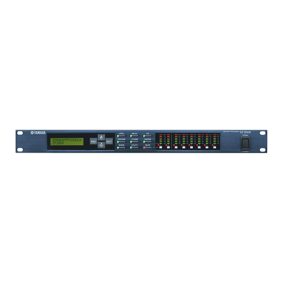
Select the corresponding channels for editing. The [SEL] key LED for each selected channel lights up. % Meters Display the channel level meters and the Limiter indicators for Output channels. ^ [POWER ON/OFF] Key Turns mains power to the SP2060 on and off. SP2060 Owner’s Manual... -
Page 23: Rear Panel
• The maximum length of a cable between a switching hub and the SP2060 is 100 meters. Due to the quality of cables and switching hub performance, however, proper operation at the maximum length cannot be guaranteed in some cases. -
Page 24: Panel Operation
Press the [▲INC]/[▼DEC] keys to adjust the input or output level. IN B LEVEL =-138.00dB NOT E When INPUT A/B LINK is turned On, the parameters for channels A and B are linked and set to the same value automatically. SP2060 Owner’s Manual... -
Page 25: Delay
TIME = SP2060 Owner’s Manual EQ (Equalizer) An EQ boosts or cuts the level of specified frequency ranges. The SP2060’s internal EQ processes input and output sig- nals. Input EQ You can apply eight-band EQ to Input channels A, B, and SUM. -
Page 26: Output Eq
A horn speaker typically features a roll-off in the higher frequency component. Horn EQ corrects this characteristics. For this purpose, the gain is limited to 0dB or higher, and the frequency to 500Hz or higher. SP2060 Owner’s Manual Function Sets the bypass for each frequency range to On or Off. -
Page 27: Routing
SOURCE = ANA A/A NO T E Signals are muted while they are switched between analog and digital to avoid noise. SP2060 Owner’s Manual Output routing You can route Input channel A, B, and SUM signals to the Crossover input. -
Page 28: X-Over (Crossover)
36dB/Oct Bessel 48dB/Oct AdjustGc 48dB/Oct Butrwrth 48dB/Oct Bessel 48dB/Oct Linkwitz FREQ 20.0Hz–20.0kHz (Frequency) –6dB through +6dB SP2060 Owner’s Manual Function Selects an attenuation amount per octave, and a type of filter. If you select “Thru,” no filter will be applied. -
Page 29: Library
Panel Operation NO T E • The type names are abbreviated on the SP2060 screen. For example, “24dB/Oct Bessel” is displayed as “24Bessel.” • Gc page is displayed if you select “Adjust Gc” for the Type parameter. • Thru No filter is applied. The original characteristics are kept with no attenuation for all frequency ranges. -
Page 30: Limiter
SCENE About a scene The SP2060 enables you to store various parameter settings as part of scene, and recall them via the front panel or re- motely from DME Designer. You can store the following settings in a scene: •... -
Page 31: Recalling A Scene
NO T E After you recall a scene, if you edit a parameter, an appears in the lower right corner on the screen. SP2060 Owner’s Manual Recalling a scene Follow the steps below to recall a scene (1–99): H IN T You can also recall a scene using the DME Designer application. -
Page 32: Storing A Scene
Press the [NEXT] key to move the cursor to the scene property icon. SCENE EDIT 73:FOH(Event A) Press the [▲INC]/[▼DEC] keys to turn protection on or off. The protection icon flashes. SCENE EDIT 73 FOH(Event A) SP2060 Owner’s Manual... -
Page 33: Deleting A Scene
Scene Delete display. NO T E You cannot delete preset scenes, protected scenes, and current scene. SP2060 Owner’s Manual UTILITY The Utility function enables you to view the word clock sta- tus and make network settings. See page 37 for more infor- mation on making network settings. -
Page 34: User Lock
• You can mute or unmute, or cancel User Lock even if the User Lock function is turned on. • The User Lock function is effective only for the panel controls on the SP2060, and does not affect any control signals from external devices. Press the [UTILITY] key to select the Utility display. -
Page 35: Displaying The Label
The selection is applied and the unit returns to the Last Memory Resume page. Displaying the label You can view the label for the SP2060 that you have set on DME Designer. Press the [UTILITY] key to select the Utility display. -
Page 36: Checking The Backup Battery
Yamaha dealer to replace the backup battery. H IN T If there is any issue with the backup battery, the SP2060 displays “Low Battery,” “Critical Battery,” or “No Battery” when you turn on the power to the unit. -
Page 37: Mute
The channel audio is muted and the [MUTE] key LED lights up. Pressing the channel [SEL] key repeatedly tog- gles between Mute on and off. NO T E You can mute or unmute even if the User Lock function is turned SP2060 Owner’s Manual... -
Page 38: Network Settings
A “device group” is a group of multiple SP2060 units that can be operated in sync via DME Designer. Follow the steps below to assign each SP2060 in a device group as master or slave. Each device group must have one master. All other de- vices in the group are assigned as slave. -
Page 39: Setting The Master Id
SP2060 in the same group via com- munication. Follow the steps below to set the master ID on the slave SP2060 units. Use the 4th octet of the IP address of the master unit as the Master ID parameter value. -
Page 40: Viewing The Mac Address
Network Settings Viewing the MAC Address Follow the steps below to view the SP2060 MAC address: NOT E In some cases, you may not need to set the MAC address via the DME-N Network driver when the SP2060 is communicating with DME Designer. -
Page 41: References
• The default value of the threshold level has been specified based on the maximum analog output level of +24dBu and amp voltage gain of 26dB (which corresponds to “ATT –6dB” if you are using a Yamaha PC series amplifier that features a voltage gain of 32dB). -
Page 42: Libraries For 1-Way Speaker Processors
Libraries for 1-way speaker processors NO T E These libraries also apply to 2-way speakers that are used in passive mode. The following table shows typical subwoofer settings when it is combined with Yamaha In- stallation Series speakers. Target speakers... -
Page 43: Libraries For 2-Way Speaker Processors
These libraries also apply to 3-way speakers (including a combination of IL series and IH series speakers) that are used in bi- amp mode. The following table shows the settings for Yamaha Installation Series speakers (full-range, bi-amp mode). Target speakers... -
Page 44: Libraries For 3-Way Speaker Processors
IF3115/95 IH2000/64 IH2000/95 * This setting is for full-range speakers. Subwoofer settings are not included. The following table shows the settings for Yamaha Installation Series speaker IL series along with IH series. Target speakers IL1115 and IH2000/64 IL1116 and IH2000/95... -
Page 45: Display Messages
Designer does not match the real configuration. System Error A system error has occurred. * Do NOT turn off the power to the SP2060 while the unit displays the message “DO NOT TURN OFF!” at the bottom of the display. SP2060 Owner’s Manual Action Change the IP addresses so that there are no duplicates. -
Page 46: Status Messages
Deleting a scene. Do NOT turn power off while the unit displays this message. * Do NOT turn off the power to the SP2060 while the unit displays the message “DO NOT TURN OFF!” at the bottom of the display. -
Page 47: General Specifications
OUTPUT 1–6 AES/EBU *Dynamic range is measured with a 6dB/octave filter @12.7kHz; equivalent to a 20kHz filter with infinite dB/octave attenuation. SP2060 Owner’s Manual Normal Rate: 44.1, 48 kHz (±0.1%) Double Rate: 88.2, 96 kHz (±0.1%) 96 kHz Less than 761 µ sec (INPUT to OUTPUT @Fs=96kHz) Key indicators x 9 MUTE indicators (INPUT A/B, OUTPUT 1–6) -
Page 48: Input/Output Characteristics
Data length Level 24 bit RS422 Units –80 –80 Units dBFS dBFS dBFS dBFS dBFS dBFS dBFS dBFS dBFS dBFS dBFS Connector XLR-3-31 type (balanced) *1 Connector XLR-3-32 type (balanced) *1 Connector XLR-3-31 type (balanced) *1 *2 SP2060 Owner’s Manual... -
Page 49: Connector Pin Assignment
References Control I/O Characteristics Terminal Network Connector Pin Assignment [NETWORK] Connector (100Base-TX Ethernet, RJ-45) Connection TxD+ TxD- RxD+ Unused Unused RxD- Unused Unused SP2060 Owner’s Manual Format Level IEEE 802.3 10Base-T/100Base-TX Connector RJ-45... -
Page 50: Dimensions
References Dimensions * Specifications and descriptions in this owner's manual are for information purpose only. Yamaha Corp. reserves the right to charge or modify products or specifications at any time without prior notice. Since specifications, equipment or options may not be the same in every locale, please check with your Yamaha dealer. -
Page 51: Index
Firmware Version ...7 Front Panel ...21 General Specifications ...46 Ground Screw ...22 H.SHELF(High Shelving) ...24 HPF ...24 Initializing the SP2060 ...35 INPUT A/B LINK ...32 INPUT A/B LINK page ...32 Input channel A ...26 Input channel B ...26 Input channel SUM ...26 [INPUT] Connectors ...22... - Page 52 MAC Address page ... 39 Master ... 37 Master ID page ... 38 Meters ... 21 Multi Zone ... 16 Multiple SP2060 ... 19 Mute ... 36 [MUTE] Key ... 21 [NETWORK] Connector ... 22 Network Settings ... 37 [NEXT/RECALL] Key ... 21 octet ...
- Page 53 MEMO SP2060 Owner’s Manual...
- Page 54 MEMO SP2060 Owner’s Manual...
- Page 55 MEMO SP2060 Owner’s Manual...
- Page 56 For details of products, please contact your nearest Yamaha representative or the authorized distributor listed below. Pour plus de détails sur les produits, veuillez-vous adresser à Yamaha ou au distributeur le plus proche de vous figurant dans la liste suivante.
- Page 57 Yamaha Pro Audio global web site: http://www.yamahaproaudio.com/ Yamaha Manual Library http://www.yamaha.co.jp/manual/ U.R.G., Pro Audio & Digital Musical Instrument Division, Yamaha Corporation © 2006 Yamaha Corporation WG50780 605IPDHx.x-02B0 Printed in Japan This document is printed on chlorine free (ECF) paper with soy ink.