
Related Manuals for FUTABA 9ZAP - PART1


Summary of Contents for FUTABA 9ZAP - PART1
- Page 1 Futaba DIGITAL PROPORTIONAL RADIO CONTROL PCM1024ZA PCM1024ZH PULSE CODE MODULATION SYSTEM...
- Page 2 Japanese low to such purposes. The laws of other countries may similarly r e s t r i c t the use of t h i s p r o d u c t . Futaba is not responsible for any use that is not in compliance with applicable law.
-
Page 3: Table Of Contents
V-Tail [ V T L ] ......32 Using Your Futaba System Contents... 16 Rudder—Aileron [R-A]... -
Page 4: System Features
Manual Introductory Section Futaba's PCM 1024Z series of radio con- Built into the system are a number of menus designed to make it simple to tailor trol systems is the most sophisticated avail- able for aircraft, helicopters, and sailplanes. the system's programs for YOUR aircraft. -
Page 5: Introduction
PCM1024Z transmitters. gramming features, but if you are in a hur- All in a l l , the Futaba PCM1024Z is the ry, follow the example set-up instructions most advanced radio control system in the in the beginning of the model setup proce- world —... -
Page 6: System Usage
Manual Introductory Section SYSTEM USAGE The PCM 1024Z system that you have just Finally, you will find the Condition Menus. purchased has been designed to be the most versa- These menus are customized to the different types of models the PCM 1024Z system will accommo- tile radio system possible. - Page 7 Manual Introductory Section Startup Menu Shows during regular operation System Menu Settings that apply to all models in storage Model Menu 1 Model Menu 2 Model Menu 10 Settings for Settings for Settings for Model #1 Model #2 Model #10 Condition Menus Condition Menus Condition Menus...
-
Page 8: Manual Layout
Futaba Manual very hopeful. Please feel free to write to Futaba if you feel that any corrections or clarifica- system. Next is a section on general operational principles, including adjustments that you can tions should be made. -
Page 9: Flying Safety
Manual Introductory Section FLYING SAFETY Safety is very important when you are flying Please maintain your system properly. Install it in your aircraft using the proper procedures, radio-controlled models. If you fail to follow the installation, setup, and operation instructions in inspect the model frequently for correct operation and structural and control authority, and be cer- this manual, or if you ignore warnings or rules set... - Page 10 Manual Introductory Section If you are using the Synthesized transmitter module FP-TK-FSS, be sure that you know the transmitting frequency before switching on. If you don't know the frequency, hold the [A] or [ R ] key down as you switch on power. The transmitting frequency will be displayed but radio transmission is deactivated.
-
Page 11: Notable System Features
Manual Introductory Section PCM 1024Z NOTABLE SYSTEM FEATURES • The optional CAMPac memory module stores up • Large Liquid Crystal Display and Soft Keys to 10 model setups, and may be exchanged be- make model programming and data input easy. tween different PCM 1024Z transmitters so that Inputs change memory instantly, so immediate model data may be rapidly transferred, or... -
Page 12: Pcm 1024Z System Contents
Manual Introductory Section PCM 1024Z SYSTEM CONTENTS Manual Introductory Section, Page 10... -
Page 13: Power-On Screen Displays
Manual Introductory Section POWER ON SCREEN DISPLAYS key, or wait a few moments to display the starting After the transmitter's power switch is turned screen. on, the current model number and name is dis- The Home screen displays the user's name, the played (see next page for what happens on the active model memory and flight condition, the initial turn-on). -
Page 14: Working With The Campac Memory Module
Manual Introductory Section WORKING WITH THE CAMPAC MEMORY MODULE The optional CAMPac Memory Module can be The CAMPac can store and memorize as many used to store model setup data separately from the as 16 sets of model data, depending on the number transmitter. -
Page 15: Using The Soft Keys
Manual Introductory Section USING THE SOFT KEYS The soft keys are used to call up the different menus during operation and programming. For example, to call up the System Menu from the home screen shown above, press the Q key (next to the SYS label). -
Page 16: Operation Without Radio Transmission
Manual Introductory Section OPERATION WITHOUT RADIO TRAMSMISSION If you'd like to make some small corrections to will be using. When you power up the system this a setup OR find out what frequency the Synthe- way, check to be sure that the "ON AIR" display sizer module is set for without radiating AND is not on. -
Page 17: System Status And Alarm Displays
Return the 4 CAUTION: SPECIAL MIX FNCT IS ACTIVE system to the Futaba service center for assistance. The This message and alarm are activated when the transmitter life of the lithium battery varies, but is usually at least is turned on with a mixing switch activated. -
Page 18: Using Your Futaba System Contents
Using Your Futaba System: Contents Radio Installation ....... . -
Page 19: Radio Installation
AM radio during a thunderstorm. or move it outside of the model fuselage. Your Futaba radio set is resistant to electrical noise, but no set may be made completely im- mune. For best flying range, avoid metal-to-metal Switch Harness Installation contact wherever possible. -
Page 20: Charging & Direct Servo Connect Operation
CHARGING & DIRECT SERVO CONNECT OPERATION Battery Charging the battery has not been used for some time, it Your Futaba FP-9ZAP and -9ZAH system is may take several charge/discharge cycles before equipped with rechargeable Nickel-Cadmium bat- the battery resumes its full-capacity flight dura- teries. -
Page 21: Stick Length Adjustment
Manual Introductory Section STICK LENGTH ADJUSTMENT The sticks on your PCM 1024Z System feature clockwise. Move the tip to the desired position, non-slip ends, and the length may be adjusted to and then lock to length by moving the locking be most comfortable for the pilot. -
Page 22: Stick Angle Adjustment
Manual Introductory Section STICK ANGLE ADJUSTMENT For the comfort of the operator, the angle of the open gimbal sticks may be adjusted from 3 to the inside to 4.5° to the outside of the transmitter case. This angle is adjusted by rotating the adjust- able screw as shown in the figure. -
Page 23: Transmitter Battery Replacement
Manual Introductory Section TRANSMITTER BATTERY REPLACEMENT The transmitter battery is easily removed and replaced, making it simple to have a spare battery pack for extended flying duration. Open the battery cover and remove the re- chargeable battery pack by pulling outward on the ribbon. -
Page 24: Transmitter Rf Module
The receiver will also work with any other control device and turn on power to operate Futaba 1024 systems. For more information on normally. the synthesized system, refer to page 37. Manual Introductory Section, Page 22... -
Page 25: Flight Condition Switching
Manual Introductory Section FLIGHT CONDITION SWITCHING Flight control switching is among the most You may think of the different condition set- powerful features available in your PCM 1024Z tings as sheets of paper in a folder, and the trans- system. It is a function that allows you to change mitter as an envelope with a clear window. -
Page 26: System Menu Contents
System Section SYSTEM MENU The following controls and menus are used for system-wide settings. These are settings that are stored for, or may be used for any and all of the different model setups stored in the PCM 1024Z's memory. To select any of these keys, first select the horizontal line contain- ing the item you wish to select, using the B or C keys adjacent to the left-hand side of the screen. -
Page 27: Ms L-Model Selection
System Section MS L—MODEL SELECTION This function is used to load the settings of the available in the transmitter, and as many as 16 may desired model into the PCM 1024Z's memory. The be stored in the CAMPac. The CAMPac is not settings may be selected from either the trans- loaded with default models initially;... -
Page 28: Vlt-Battery Voltage Display
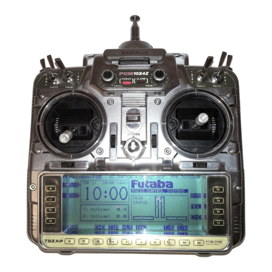
System Section VLT—BATTERY VOLTAGE DISPLAY This function may be used to check the voltage of both the transmitter and receiver batteries with a high-accuracy digital voltmeter, which continu- ously displays the measured results. The table below indicates the measurement range of the Voltage Display voltmeter. -
Page 29: Tac-Tachometer
System Section TAC—TACHOMETER The tachometer function in the PCM 1024Z Speed transmitter may be conveniently used to measure the rotational speed of any propeller or rotor blade, up to a maximum of 50,000 RPM. This is very useful for testing engine performance, rotor settings, etc. -
Page 30: Srv-Servo Cycle & Bar Graph Display
System Section SRV—SERVO CYCLE & BAR GRAPH DISPLAY This key has two different functions: a servo Check Servos By Cycling cycling mode, which slowly moves each servo to its extreme positions, and a servo bar graph indi- cation, which pictorially shows the position to which each servo is being commanded. -
Page 31: Trn-Trainer System
Control makes it possible for the instructor The training system will work with any PCM to make corrections without overriding the stu- 1024Z series transmitter. Futaba's 5U and 7U dent's inputs. Two transmitters must be connected series of transmitters may also be connected for a by an optional Trainer/Data Transfer cord, and the student's usage. -
Page 32: Dtn-Data Transfer Function
System Section DTN—DATA TRANSFER FUNCTION This function may be used to exchange model transfer data depends on the number of flight con- ditions, and ranges from 1 to 18 seconds. setup data between two PCM 1024Z transmitters. Data Transfer Mode Setup Identical model setups are needed for trainer oper- First, connect the two PCM 1024Z transmitters ation, and it is also useful to transfer data to a... -
Page 33: Cpm-Copy Model Function
System Section CPM—COPY MODEL FUNCTION This function is used to copy one set of model be used to make a backup copy of a model setup before making changes. data into a second memory within the same trans- mitter. This function is very handy because it may The CPM function may be used to copy to and from the optional CAMPac as well. -
Page 34: C Pc-Copy Condition Function
System Section C PC—COPY Condition Function This function may be used to copy individual The entire model data may be copied under the flight conditions. One use would be to copy the following conditions: default flight condition, with all its subtrims, 1. -
Page 35: Par- Parameters
System Section PAR— PARAMETERS (SETS AUTO-OFF AND SCREEN CONTRAST) This menu has two functions: the first auto- ed if left on accidentally. The delay period until matically turns off transmitter power after a shutdown may be selected from 10 to 40 minutes certain (settable) period of transmitter inactivity, in ten minute increments, or the power off func- and the second may be used to adjust the contrast... -
Page 36: Una-User Name Registration
Additionally, a special password feature allows to your system, and you'll have to return the unit the user to define a four-digit password to protect to Futaba to be reset. the model memory contents. Without entering the correct password,... - Page 37 System Section FRQ—TRANSMITTER FREQUENCY SETTING (9ZAPS/HPS ONLY) The exclusive Frequency Synthesizer System It is necessary to cycle the transmitter's power Module (FP-TK-FSS) allows you to switch your to broadcast on the selected frequency. When you transmission frequency in software! No longer do do this, the channel number and frequency are dis- played on the Home Screen.
-
Page 38: Setting The Frequency Synthesizer Receiver
System Section SETTING THE FREQUENCY SYNTHESIZER RECEIVER When the receiver is turned on, the frequency The following procedure should be followed in set by the rotary switches is used by the receiver. order to change the receiving frequency on a syn- If the switch is changed during operation, the thesized receiver. -
Page 39: Swt - Switch Setting
System Section SWT—SWITCHING SETTING This function may be used to define which function, this may be done also! You can make switch activates a particular function. The versatili- any motion of any switch or stick on the trans- ty of the PCM 1024Z system allows you to define mitter activate or deactivate any switchable func- switches for the following purposes: special mix- tion. - Page 40 System Section Setting the Activation Switch Setting Volume Controls From many different commands, the switch setting Some functions may be controlled by either stick position or knobs/sliders (for example. Pitch Curve in the function may be displayed by pressing the SWT ( P ) key.
-
Page 41: Model Setting Section Contents
Model Setting Section MODEL SETTING SECTION The following controls and menus are used for model settings. These are settings that may be used individually for any and all of the different model setups stored in the PCM 1024Z's memory. Each model setup can have different model settings —... -
Page 42: Csl-Condition Select
One of the most powerful features of the when a new model type is defined. This condition Futaba PCM 1024Z system is the ability to allocate is always on, and remains on until other conditions as many as eight different flight conditions to a are activated by switches. -
Page 43: Tim-Timers & Elapsed Time Counter
Model Setting Section TIM—TIMERS & ELAPSED TIME COUNTER The Timer function may be set for any desired Each timer may be set for countdown or count- time, i.e. engine run time, specified times for com- up operation with a target time. If a target time is set and the timer reaches the set time, a buzzer petitions, etc. -
Page 44: F/S-Failsafe/Hold Setting
Model Setting Section F/S—FAILSAFE/HOLD SETTING The Failsafe function may be used to set up little power remaining. In this case, the throttle is positions that the servos move to in the case of moved to the defined failsafe position, or if one was not defined, to a medium speed position. -
Page 45: Pmd - Pulse Mode Fm/Pcm
Model Setting Section PMD—PULSE MODE (SWITCHING FM/PCM) The PMD function allows you to select the depends on the type of receiver being used. If you transmission mode that your PCM 1024Z uses. change the mode of transmission, you need to You may select between PCM (Pulse Code Modula- cycle the power switch Off and the On before it tion) and PPM (Pulse Position Modulation, also... -
Page 46: Rev-Servo Reversing Function
Model Setting Section REV—SERVO REVERSING FUNCTION This function is used to reverse the direction a servo operates for a given command. This function should be used AFTER any special menus are de- fined to assure that all servos are moving the cor- rect directions. - Page 47 Model Setting Section FMC—FUNCTION CONTROL The Function Control Menu may be used to You may also use this function to select the define the relationship between the transmitter trim positions, independently from the sticks. For controls and the receiver output channels. Any instance, to set cross trims, simply exchange the function on the transmitter may control any elevator (CH2) and throttle (CH3) trim positions.
-
Page 48: Rst-Data Reset
Model Setting Section RST—DATA RESET This function is designed to allow you to reset PMIX ..Clears all programmable mixers selected portions — or all — of the settings saved in SMIX ..Resets all special mixing func- the active memory. -
Page 49: Cut-Engine Cut
Model Setting Section CUT—ENGINE CUT Airplane Helicopter This function may be used to define a switch Offset Direction Position setting that may be used to cut the engine. It will only work when the throttle stick is at the low side;... -
Page 50: Chd-Condition Hold
Model Setting Section CHD—CONDITION HOLD This function may be used to limit the maxi- You must deactivate this function when you are mum speed of the engine so that you may adjust through making adjustments. The system will not flight conditions when the engine is running. The allow you to deactivate this function in either of maximum throttle position is settable, and an the following states:... -
Page 51: Typ-Model Type Selection
Model Setting Section TYP—MODEL TYPE SELECTION This function is used to select the type of When the Model Type Selection command is model from airplane, helicopter, and sailplane. invoked, all the data in the active memory is Sailplanes may be set up with either two wing cleared. -
Page 52: Ch9-Channel 9 Switch Definition
Model Setting Section CH9—CHANNEL 9 SWITCH DEFINITION Your PCM 1024Z system has nine channels. The ninth channel is a switch channel, and the location of the switch may be selected with this menu. The default switch is SW(B), with its ON SW(B) position at Position 2. -
Page 53: Mna- Model Name Definition
Model Setting Section MNA— MODEL NAME DEFINITION This function may be used to input or change the name of the model in active memory. This can be very useful to tell different models settings apart. Each model name can be as long as eight characters, and the model name always appears in the top center of the display screen. -
Page 54: Alt-Alternate Switch
Model Setting Section ALT—ALTERNATE SWITCH This function allows the spring-loaded switch and releasing again turns it off. Therefore, the ALT mode creates a PULL-ON, PULL-OFF switch. operation to be defined in two different ways. The default definition is that the switch is off unless it For example, while using the trainer system the is moved against spring tension to its second posi- ALT function allows the instructor to release the... -
Page 55: Thr-Throttle Curve
Model Setting Section THR—THROTTLE CURVE The Throttle Curve function applies only to The throttle curve divides the full travel of the Airplanes and Helicopters. Its purpose is to select throttle stick into twelve segments separated by whether the throttle curve function is to be used thirteen points. -
Page 56: Swh-Swashplate Type
Model Setting Section SWH—SWASHPLATE TYPE This function is used to define which type of swashplate mixing is to be used for the active helicopter model. The mixing functions should be selected to match the swashplate on the model. Swashplate Type Setting Procedure S-2 Type S-1 Type Use this type for helicopters with conventional linkages. - Page 57 Model Setting Section Swash Plate Selection Procedure In the Model Menu, press the SWH key to get the Swash Plate Selection menu. Return to Model Menu Type Selection Keys Use the (A) key to activate the selection menu, then use the E to D type selection keys to choose the type matched to your model.
-
Page 58: Rdr-Rotor Direction
Model Setting Section RDR—ROTOR DIRECTION This function is used to tell your PCM 1024Z properly set the mixing directions. The rotation system the rotor rotational direction, so it can direction, when viewed from the top, is entered. Rotor Direction Setting Procedure In the Model Menu, press the RDR key to get the Rotor Direction Setting menu. -
Page 59: Inv-Inverted Pitch
Model Setting Section INV—INVERTED PITCH This function is used to activate inverted flight Pitch Servo functions for the model in active memory. This function allows the inverted flight to use the normal flight functions (the linkages must be adjusted for inverted flight, however). The position at which the normal-inverted low side pitches cross ("cross position") can be set. -
Page 60: Pit-Pitch Curve
Model Setting Section PIT—PITCH CURVE The Pitch Curve function applies only to Heli- copters. Its purpose is to select whether the pitch curve function is to be used with the active model. The pitch curve divides the full travel of the stick into twelve segments separated by thirteen points. -
Page 61: Common Conditions
Common Condition Section COMMON CONDITIONS SECTION This section contains information on how to use the model condi- tions that are common to ALL types of models, including such as throw volumes, dual rates, programmable mixes, subtrims, and condi- tion naming. This material should be used in conjunction with the Condition Settings sections for each type of aircraft, following this section. - Page 62 Common Condition Section ADJUSTABLE TRAVEL VOLUME (ATV) The ATV function adjusts the servo left and mode. NOTE: Stick movement is indicated by the right throws, and to generate differential throws " " "symbol on the screen. and correct for linkages. The travel rate can be Included in this function is the servo delay varied from 1% to 140% in each direction on chan- setting menu.
- Page 63 Common Condition Section Programming Servo Delay at Condition Switching might be used, for example, to prevent a sudden loss of lift on a sailplane when switching from flaps down for This function is used to set the servo delay for each launch to a regular position for normal flight.
- Page 64 Common Condition Section ADJUSTABLE FUNCTION RATE (AFR) This function is used to adjust the throw and exponential produces normal straight-line response. operation curve of the stick, lever, and switch In the EXP1 mode, the servo movement near functions (CH1 to CH8) for each flight condition. the neutral position can be made sensitive or in- This is normally used after ATV has defined the sensitive.
- Page 65 Common Condition Section Mode selection Linear Mode Mixing Press the Mode Selection A key. then press the NXT To set the linear mode, do the following: press the A L key to get to the mode setting menu. To choose the key, then press the LIN H key.
- Page 66 Common Condition Section DUAL RATES AND EXP CURVE SWITCHING Programming this function allows the EXP2 mode may be used to control the rise of the curve, either steep or gradual as the stick is change the function operation rate and operation moved.
-
Page 67: C O N T E N T S
Common Condition Section PROGRAMMABLE MIXING (PMX) Programmable mixing may be used to correct Any two channels can be mixed in each of the five available mixing circuits. Each mix circuit undesired tendencies of the aircraft, and may be may use one of three mixing types. For Linear- used for unusual control configurations. - Page 68 Common Condition Section Programming the Mixers Mixing ON/OFF switch selection and ON/OFF direction setting Activation of command When a mixer is first activated, an ON/OFF switch is In the Condition Menu, press the PMX key to get the not defined. If you wish to define an on/off switch to PROG MIX menu shown as Screen 1 in the top of the control the mixing, call the switch setting screen by illustration below.
- Page 69 Common Condition Section For the 7-Point Curve mixing method, each of the with the rate control specified by the slider control that points on the curve must be defined. To set the points, controls the camber. Note that if you have differential set first select the point with movement keys Q and R.
- Page 70 Common Condition Section SUBTRIM (STM)—SERVO NEUTRAL ADJUSTMEMT The Subtrim function is used to set the servo and pushrods are hooked up. When you begin to neutral position, and may be used to make fine set up a model, be sure that the digital trims are set to their center position (page 71).
- Page 71 Common Condition Section TRIM OFFSET (TOF) The Trim Offset function may be used to set a be programmed within Trim mixes 1 and 2 (TM1, trim offset for different flight conditions. For TM2). Helicopters, this is very useful to set offsets when You may set a time delay to slow down the the Pitch ->...
- Page 72 Common Condition Section CONDITION NAME REGISTRATION (CNA) We recommend that you register a name that is This function may be used to name the active flight condition, and can be a maximum of five easy to remember for easy confirmation of the characters long.
- Page 73 Common Condition Section DIGITAL TRIM (TRM) The Digital Trim function may be used to Normal mode is suitable for centering controls such as the transmitter sticks, and trimming is program how the trims change as the force changes on the trim tab switches. When you press lightly performed at the neutral position.
- Page 74 Common Condition Section Screen 2 Trim Mode Stepping Setting Rate First Delay-Rate Repetition Step Setting Speed Stepping Value of Rate Subtrim Second Step Repetition Speed Return To Condition Menu Mode Selection Keys Trim Mode Selection you may set the step rate with the rate setting keys E to To select the trim mode, first press the A key.
-
Page 75: Airplane Section Table Of Contents
Airplane Section AIRPLANE SECTION This section contains information on the commands that apply to powered aircraft only. Each of these functions can be set independ- ently for different flight conditions. For conditions that apply to all models (ATV, AFR, D/R, PMX, STM, TOF, CNA, and TRM functions), refer to the Common Condi- tions section. -
Page 76: Airbrake [ A B K ]
Airplane Section AlRPLANE CONTROLS AND FUNCTIONS Functions and locations given in this drawing are the factory default positions, which occur upon startup. Each setting can be easily changed as the owner desires. The Function Change menu [FNC] may be used for this purpose. Carrying Handle CAMPac Memory Module 6. - Page 77 Airplane Section Note that all stick & switch positions may be changed Aileron Control Collective Mixing Idle-Up Lever Throttle Control . . . (MODE II) Raises the engine idling speed at the variable Elevator Control . . . (MODE I) pitch propeller LOW side.
- Page 78 Airplane Section AIRPLANE RECEIVER AND SERVO CONNECTIONS The receiver output order is shown below: 1. AIL Aileron (Ail 1 if FPN or ADF on. Elevon 1 if EVN on) 2. ELE Elevator (V-Tail 1 if VTL on, Elevon 2 if EVN on) 3.