
Related Manuals for Dell Precision YT583


Summary of Contents for Dell Precision YT583
- Page 1 Dell Precision™ T7400 User’s Guide Model DCDO w w w . d e l l . c o m | s u p p o r t . d e l l . c o m...
- Page 2 Other trademarks and trade names may be used in this document to refer to either the entities claiming the marks and names or their products. Dell Inc. disclaims any proprietary interest in trademarks and trade names other than its own.
-
Page 3: Table Of Contents
System Board Components Specifications Advanced Features LegacySelect Technology Control Manageability Alert Standard Format Dell OpenManage™ IT Assistant Dell OpenManage Client Instrumentation Power Management About RAID Configurations RAID Level 0 RAID Level 1 .... - Page 4 RAID Level 5 RAID Level 10 Configuring Your Computer for RAID RAID Configuration Utility Entering the RAID Configuration Utility Navigating Within the Configuration Utility RAID Configuration and Management Exit Screen Performing Configuration Tasks Creating a RAID Level 0 Configuration Creating a RAID Level 1 Configuration Creating a Second RAID Volume Viewing RAID Volume Properties Synchronizing a RAID Volume (Virtual Disk)
- Page 5 Uninterruptible Power Supplies Securing Your Computer Chassis Intrusion Detection Removing the Chassis Intrusion Switch Replacing the Chassis Intrusion Switch Resetting the Chassis Intrusion Detector Security Cable Lock Passwords ......About Passwords Using a Primary (or System) Password Using an Administrator Password...
- Page 6 Option Settings Selecting the Boot Device for the Current Boot Changing Boot Sequence for Future Boots Booting to a USB Device Clearing Forgotten Passwords Clearing CMOS Settings Flashing the BIOS Cleaning Your Computer Computer, Keyboard, and Monitor Floppy Drive CDs and DVDs Troubleshooting Solving Problems Battery Problems...
- Page 7 Error Messages Dell Diagnostics When to Use the Dell Diagnostics Starting the Dell Diagnostics From Your Hard Drive 124 Starting the Dell Diagnostics From the Drivers and Utilities Media Dell Diagnostics Main Menu 11 Reinstalling Software Drivers ......
- Page 8 12 Adding and Replacing Parts Before You Begin Recommended Tools Turning Off Your Computer Before Working Inside Your Computer Removing the Computer Cover and Front Panel Removing the Computer Cover Removing the Front Panel Replacing the Front Panel and Computer Cover Replacing the Front Panel Replacing the Computer Cover I/O Panel...
- Page 9 Addressing Memory With 4-GB or Greater Configurations (32-bit Operating Systems Only) Removing Memory Without Memory Riser Cards Memory Installation (With Optional Memory Riser Cards) 179 Installing Memory (With Optional Memory Riser Cards) 180 Removing Memory (With Optional Memory Riser Cards) 187 Cards .
- Page 10 Obtaining Assistance Problems With Your Order Product Information Returning Items for Warranty Repair or Credit Before You Call Contacting Dell 14 Appendix FCC Notice (U.S. Only) Glossary 291 Contents ..... .
- Page 11 Contents...
- Page 12 Contents...
-
Page 13: Finding Information
Finding Information NOTE: Some features or media may be optional and may not ship with your computer. Some features or media may not be available in certain countries. NOTE: Additional information may ship with your computer. Finding Information... - Page 14 You can use the Drivers and Utilities disc to reinstall drivers (see "Reinstalling Drivers and Utilities" on page 130), or to run the Dell Diagnostics (see "Dell Diagnostics" on page 123). Documentation and drivers are already installed on your computer.
- Page 15 • How to set up my computer • How to care for my computer • Basic troubleshooting information • How to run the Dell Diagnostics • How to set up a printer • How to open my computer • Warranty information •...
- Page 16 These labels are located on your computer. • Use the Service Tag to identify your computer when you use support.dell.com or contact support. • Enter the Express Service Code to direct your call when contacting support. NOTE: As an increased security measure,...
- Page 17 • Service and support — Service call status and support history, service contract, online discussions with technical support • Dell Technical Update Service — Proactive e-mail notification of software and hardware updates for your computer • Reference — Computer documentation,...
- Page 18 What Are You Looking For? • How to use Microsoft Windows Vista™ • How to work with programs and files • How to personalize my desktop • How to reinstall my operating system Finding Information Find It Here Windows Help and Support Click the Windows Vista Start button , and then click Help and Support.
- Page 19 What Are You Looking For? • How to use Linux • E-mail discussions with users of Dell Precision™ products and the Linux operating system • Additional information regarding Linux and my Dell Precision computer Find It Here Dell Supported Linux Sites •...
- Page 20 Finding Information...
-
Page 21: About Your Computer
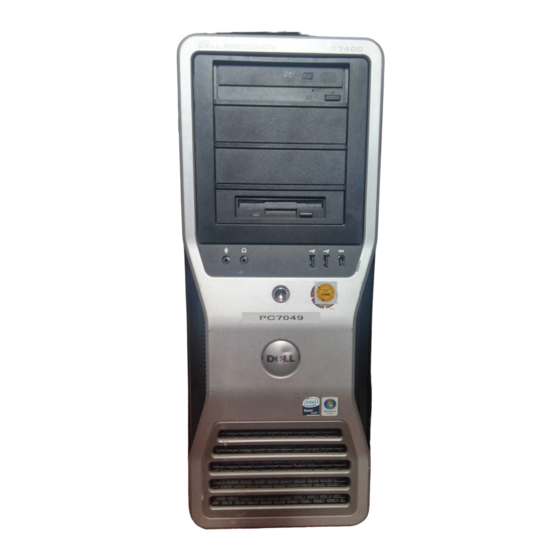
About Your Computer Front View of the Computer About Your Computer... - Page 22 5.25-inch drive bays 5.25-inch drive bay with special 3.5-inch drive panel plate hard-drive activity light IEEE 1394 connector USB 2.0 connectors (2) power button, power light network link light diagnostic lights About Your Computer Can hold an optical drive, Media Card Reader, floppy drive, or SATA hard drive in a 5.25-inch drive bay carrier.
-
Page 23: Back View Of The Computer
microphone connector headphone connector Back View of the Computer power connector card slots back panel connectors CAUTION: Ensure that none of the system air vents are blocked. Blocking them would cause serious thermal problems. Use the microphone connector to attach a personal computer microphone for voice or musical input into a sound or telephony program. -
Page 24: Back Panel Connectors
Back Panel Connectors parallel connector Connect a parallel device, such as a printer, to the parallel mouse connector IEEE 1394 connector line-in connector line-out connector Use the green line-out connector to attach most speakers with About Your Computer connector. If you have a USB printer, plug it into a USB connector. - Page 25 link integrity light Green — A good connection exists between a 10-Mbps network and the computer Orange — A good connection exists between a 100-Mbps network and the computer Yellow — A good connection exists between a 1000-Mbps (or 1-Gbps) network and the computer Off —...
-
Page 26: Inside View
Inside View About Your Computer power supply hard drive bay memory shroud NOTICE: The memory shroud holds the (optional) memory riser cards in place; its thumbscrews must be sufficiently tight in order to secure the risers and to avoid damage. 5.25-inch drive bay 5.25-inch drive bay with 3.5-inch drive panel plate... -
Page 27: System Board Components
System Board Components card fan front fan About Your Computer... - Page 28 primary processor connector (CPU_0) secondary processor connector (CPU_1) front fan connector (FAN_FRONT) card cage fan (FAN_CCAG) internal speaker connector (INT_SPKR) power connector (POWER2) USB (INT_USB) auxiliary hard drive LED (AUX_LED) password jumper (PSWD) 10 auxiliary power LED (AUX_PWR) 11 SATA connectors for hard drives or optical drives (SATA_0, SATA_1, SATA_2) 12 main power connector (POWER1)
-
Page 29: Specifications
Specifications NOTE: Offerings may vary by region. For more information regarding the configuration of your computer, click Start→ Help and Support and select the option to view information about your computer. Processor Processor type Internal cache External bus frequency Memory Memory module connectors Memory module capacities Memory type... - Page 30 (continued) System Information Flash EPROM Graphics bus Expansion Card support Cards supported connector connector size connector data width (maximum) bus transfer rate PCI-X connectors connector size connector data width (maximum) bus transfer rate PCI Express x8 (wired as x4) connectors connector size connector data width (maximum) bus transfer rate...
- Page 31 Expansion connector connector size connector data width (maximum) bus transfer rate Ports and Connectors External connectors: Serial Parallel IEEE 1394 Network adapter PS/2 (keyboard and mouse) Audio System board connectors: Floppy drive SAS/Serial ATA HDD Serial ATA Internal USB Video Video type two x16 slots (support x16, x8, x4 and x1 modes/cards)
- Page 32 Audio Audio type Stereo conversion Drives Externally accessible Internally accessible Key Combinations <F2> <F12> or <Ctrl><Alt><F8> <Ctrl><Alt><F10> <F5> Controls and Lights Power control Power light About Your Computer High Definition Audio CODEC and Azalia/High Definition digital controller 24-bit analog-to-digital; 24-bit digital-to- analog four 5.25-inch universal drive bays (can support 3.5-inch devices)
- Page 33 Controls and Lights Hard-drive access light Link integrity lights Activity light Diagnostic lights Standby power light Power DC power supply Wattage Heat dissipation Voltage Backup battery Physical Height Width Depth Front panel: green light—on when the computer reads data from or writes data to the hard drive; the light may also be on when a device such as the optical drive is operating Back panel: green light for 10-Mb operation;...
- Page 34 Physical Approximate minimum weight Environmental Temperature range Operating Storage Relative humidity (maximum) Operating Storage Maximum vibration (using a random-vibration spectrum that simulates user environment) Operating Storage Maximum shock Operating Storage Altitude (maximum) Operating Storage About Your Computer 55 lb (24.9 kg) CAUTION: Your computer is heavy and can be difficult to maneuver.
-
Page 35: Advanced Features
Control is provided to the administrator through system setup, Dell OpenManage™ IT Assistant, or Dell custom factory integration. LegacySelect allows administrators to electronically activate or deactivate connectors and media devices that include serial and USB connectors, a parallel connector, a floppy drive, PCI slots, and a PS/2 mouse. - Page 36 Connectivity Enabled/ Ethernet Connectivity Disabled For more information about Dell's ASF implementation, see the ASF User's Guide and the ASF Administrator's Guide, which are available on the Dell Support website at support.dell.com. Advanced Features Description The computer chassis has been opened or the chassis intrusion alert has been cleared.
-
Page 37: Dell Openmanage™ It Assistant
A managed system is one that has Dell OpenManage Client Instrumentation set up on a network that uses IT Assistant. For information about Dell OpenManage Client Instrumentation, see the Dell OpenManage Client Instrumentation User’s Guide available on the Dell Support website at support.dell.com. - Page 38 • Standby. In this sleep mode, power is reduced or turned off for many components. However, system memory remains active. NOTE: Hibernate mode is only supported on computers with 4-GB of RAM or less. Hibernate. This sleep mode reduces power consumption to a minimum by •...
-
Page 39: About Raid Configurations
Although there are several RAID configurations available in the computer industry for different types of uses, Dell offers RAID level 0, RAID level 1, or, with an optional PCI Express RAID controller, RAID level 5 or RAID level 10 on your Dell Precision computer. -
Page 40: Raid Level 0
NOTE: RAID levels do not represent a hierarchy. A RAID level 5 configuration is not inherently better or worse than a RAID level 0 configuration. The RAID controller on your computer can only create a RAID level 0 configuration using two to four physical drives. A RAID level 5 or 10 array (only available with the optional PCI Express RAID controller) must be made up of three or four drives. -
Page 41: Raid Level 1
NOTICE: Because RAID level 0 provides no data redundancy, if one drive fails, then the data on the other drive is also inaccessible. Therefore, ensure that you perform regular backups when you use a RAID level 0 configuration. RAID Level 1 RAID level 1 uses a data-redundancy storage technique known as "mirroring."... - Page 42 RAID level 5 uses a data-staging storage technique known as "parity checking." When a block of data is written to the RAID configuration, it is striped across all of the drives in the RAID array except for one drive, to which is written parity data.
-
Page 43: Raid Level 10
RAID Level 10 NOTE: RAID levels 5 and 10 are only available via an optional PCI Express RAID controller card. RAID level 10 uses a combination of striping and mirroring methods. It requires four drives. The drives are broken up into mirroring pairs and then the data that is written to the RAID configuration is striped across all four drives. -
Page 44: Configuring Your Computer For Raid
RAID virtual disk (a RAID volume). • If at least one RAID volume is currently configured, any existing RAID volumes are displayed for management purposes. NOTE: Dell recommends backing up your data prior to adding or updating configurations. Advanced Features... -
Page 45: Exit Screen
Exit Screen It is important to exit the RAID Configuration Utility properly, because some changes take effect only when you exit. From the Adapter List, press <Esc> to exit. In addition, a similar exit screen appears when you exit most other screens, and it can be used to save settings. -
Page 46: Creating A Raid Level 1 Configuration
NOTICE: All data will be lost upon creation of the RAID volume. Dell recommends backing up your data before performing these steps. When creating an IS (striped) RAID volume: • All drives must be either Dell compliant SAS or SATA hard drives. -
Page 47: Creating A Second Raid Volume
• Drives must have 512 byte blocks and must not have removable media. • There can only be 2 hard drives per RAID volume. 5 Press <C> and then select Save changes when the RAID volume has been fully configured. 6 Exit this menu to save the changes. -
Page 48: Synchronizing A Raid Volume (Virtual Disk)
Synchronizing a RAID Volume (Virtual Disk) When a RAID volume is synchronized, the firmware synchronizes the data on the secondary hard drive(s) with the data on the primary hard drive of the RAID level 1 volume. Follow these steps to start synchronization for a RAID level 1 volume: 1 Select Synchronize Virtual Disk. -
Page 49: Replacing And Rebuilding A Degraded Raid Volume
Replacing and Rebuilding a Degraded RAID Volume In the event of a hard drive failure in a RAID level 1 volume, you will need to replace the hard drive and resynchronize the RAID volume. 1 Replace the failed drive with a new drive of the same type and capacity (or larger capacity). - Page 50 Advanced Features...
-
Page 51: Setting Up Your Computer
Setting Up Your Computer Installing Your Computer in an Enclosure Installing your computer in an enclosure can restrict the airflow and impact your computer’s performance, possibly causing it to overheat. Follow the guidelines below when installing your computer in an enclosure: NOTICE: The operating temperature specifications indicated in this manual reflects the maximum ambient operating temperature. - Page 52 • If your computer is installed in a corner on a desk or under a desk, leave at least 5.1 cm (2 in) clearance from the back of the computer to the wall to permit the airflow required for proper ventilation. Setting Up Your Computer...
-
Page 53: Connecting To The Internet
NOTICE: Do not install your computer in an enclosure that does not allow airflow. Restricting the airflow impacts your computer’s performance, possibly causing it to overheat. Connecting to the Internet NOTE: ISPs and ISP offerings vary by country. To connect to the Internet, you need a modem or network connection and an Internet service provider (ISP). -
Page 54: Setting Up Your Internet Connection
• Dial-up connections that provide Internet access through a telephone line. Dial-up connections are considerably slower than DSL and cable (or satellite) modem connections. • Wireless LAN connections that provide Internet access using Bluetooth wireless technology. If you are using a dial-up connection, connect a telephone line to the modem connector on your computer and to the telephone wall jack before you set up your Internet connection. -
Page 55: Transferring Information To A New Computer
• If you have a CD, click Use the CD I got from an ISP. 5 Click Next. If you selected Set up my connection manually, continue to step 6. Otherwise, follow the instructions on the screen to complete the setup. NOTE: If you do not know which type of connection to select, contact your ISP. -
Page 56: Microsoft ® Windows ® Xp
® Microsoft Windows The Microsoft Windows XP operating system provides the Files and Settings Transfer Wizard to move data from a source computer to a new computer. You can transfer data, such as: • E-mail messages • Toolbar settings • Window sizes •... - Page 57 3 On the Which computer is this? screen, click New Computer→ Next. 4 On the Do you have a Windows XP CD? screen, click I will use the wizard from the Windows XP CD→ Next. 5 When the Now go to your old computer screen appears, go to your old or source computer.
- Page 58 Running the Files and Settings Transfer Wizard Without the Operating System Disc To run the Files and Settings Transfer Wizard without the Operating System disc, you must create a wizard disk that will allow you to create a backup image file to removable disc. To create a wizard disk, use your new computer with Windows XP and perform the following steps: 1 Open the Files and Settings Transfer Wizard: click Start→...
-
Page 59: Microsoft Windows Vista
#154781 (What Are The Different Methods To Transfer Files From My Old Computer To My New Dell™ Computer Using the Microsoft Operating System?). NOTE: Access to the Dell™ Knowledge Base document may not be available in certain countries. Microsoft Windows Vista™ 1 Click the Windows Vista Start button and settings→... -
Page 60: Surge Protectors
Surge Protectors Surge protectors and power strips equipped with surge protection help prevent damage to your computer from voltage spikes that can occur during electrical storms or after power interruptions. Some surge protector manufacturers include warranty coverage for certain types of damage. Carefully read the device warranty when choosing a surge protector. -
Page 61: Securing Your Computer
Securing Your Computer Chassis Intrusion Detection CAUTION: Before you begin any of the procedures in this section, follow the safety instructions in the CAUTION: To guard against electrical shock, always unplug your computer from the electrical outlet before opening the cover. NOTICE: To prevent static damage to components inside your computer, discharge static electricity from your body before you touch any of your computer’s electronic... -
Page 62: Replacing The Chassis Intrusion Switch
Resetting the Chassis Intrusion Detector 1 Turn on (or restart) your computer. 2 When the blue DELL™ logo appears, press <F2> immediately. If you wait too long and the operating system logo appears, continue to wait until you see the Microsoft Securing Your Computer ®... -
Page 63: Security Cable Lock
your computer (see "Turning Off Your Computer" on page 139) and try again. 3 Enter the system setup program (see "System Setup" on page 75). 4 Press the down-arrow key to move to the Security option. 5 Press <Enter> to access the menu. 6 Use the down-arrow key to select Intrusion Alert. -
Page 64: Passwords
security cable slot Passwords About Passwords NOTE: Passwords are disabled when you receive your computer. A primary (or system) password, an administrator password, and a hard drive password all prevent unauthorized access to your computer in different ways. The following table identifies types and features of passwords available on your computer. -
Page 65: Using A Primary (Or System) Password
• Ensure that people are not watching you when you type your password(s). If you forget any of your passwords, contact Dell (see "Contacting Dell" on page 287). For your protection, Dell technical support staff will ask you for proof of your identity to ensure that only an authorized person can use the computer. - Page 66 Option Settings You cannot change or enter a new system password if either of the following two options is displayed: Set — A system password is assigned. • • Disabled — The system password is disabled by a jumper setting on the system board.
- Page 67 6 To confirm your password, type it a second time in the Confirm New Password field and press <Enter>. 7 Press <Enter> at the prompt. The system password setting changes to Set. 8 Exit the system setup program. Password protection takes effect when you restart the computer. Typing Your System Password When you start or restart your computer, the following prompt appears on the screen:...
-
Page 68: Using An Administrator Password
2 If the Unlock Setup field is present: Use the arrow keys to navigate to the Unlock Setup field. Press <Enter> to access the field. Type in the administrator password and press <Enter>. 3 Use the arrow keys to navigate to the System Password field, and then press <Enter>. - Page 69 Assigning an Administrator Password The administrator password can be the same as the system password. To escape from the field without assigning a system password, press <Esc> at any time before you complete step 5. NOTE: If the two passwords are different, the administrator password can be used as an alternate system password.
-
Page 70: Disabling A Forgotten Password And Setting A New Password
A change to Admin Password becomes effective immediately (no need to restart the computer). Operating Your Computer With an Administrator Password Enabled When you enter the system setup program (see "System Setup" on page 75), the Unlock Setup option is displayed. If you do not type the correct administrator password into the Unlock Setup field, the computer lets you view, but not modify, system setup options. -
Page 71: Trusted Platform Module (Tpm)
To secure your TPM data and encryption keys, follow the backup procedures documented in the Broadcom Secure Foundation Getting Started Guide. In the event of these backups being incomplete, lost, or damaged, Dell will be unable to assist in the recovery of encrypted data. -
Page 72: Security Management Software
Computer tracking software may enable you to locate your computer if it is lost or stolen. The software is optional and may be purchased when you order your Dell™ computer, or you can contact your Dell sales representative for information about this security feature. -
Page 73: If Your Computer Is Lost Or Stolen
Dell for technical assistance and gives your Service Tag, the computer is identified automatically as missing or stolen. The representative will attempt to get the phone number and address of the caller. Dell will then contact the law enforcement agency to which you reported the missing computer. - Page 74 Securing Your Computer...
-
Page 75: System Setup
Certain changes can make your computer work incorrectly. Entering System Setup 1 Turn on (or restart) your computer. 2 When the blue DELL™ logo is displayed, you must watch for the F2 prompt to appear. 3 Once this F2 prompt appears, press <F2> immediately. - Page 76 Displays the Computer name, BIOS Version number, BIOS System Info Date, Service Tag, Express Service Code, and Asset Tag. Displays the following information for the processor installed Processor in the system: Info Displays the amount of Installed Memory, Memory Speed, Memory Info Memory Channel Mode, and a description of the Memory Technology.
-
Page 77: Onboard Devices
Enables and disables the floppy drives and sets read Diskette permission for the internal floppy drive. Off disables all Drive floppy drives. USB disables the internal diskette drive and (Internal enables a USB floppy drive, if the USB controller is enabled default) and a USB drive is connected. - Page 78 Enables or disables the internal USB Controller controller. No Boot enables the controller but disables the ability to boot from a USB (On default) device. NOTE: floppy drives regardless of the No Boot setting. Enables or disables the front USB ports. Front USB Ports (On default)
- Page 79 Video This field allows the user to specify the order in which the Primary system assigns the primary video controller when two or more Video controllers are available in the system. This selection is (Option 1 necessary only if there are two or more video controllers default) present.
- Page 80 HDD Acoustic Mode Snoop Filter ACL Prefetch HW Prefetch Optimization Security When an administrator password is being used, allows the Unlock Setup user access to modify system setup settings. Enter the Locked administrator password at the prompt to unlock system setup. default) If the correct password is not entered here, the user can view but not modify system setup fields.
- Page 81 Determines the interaction between the System password and Password the Admin password. Locked prevents a user without a valid Changes Admin password from being able to modify the System (Unlocked password. Unlocked allows a user with a valid System default) password to modify the system password.
- Page 82 Sets time to automatically turn on the computer. Auto Power Time Time is kept in the standard 12-hour format (hours:minutes). Change the startup time by pressing the right- or left-arrow key to increase or decrease the numbers, or type numbers in both the date and time fields.
- Page 83 Restores system setup options to their factory defaults. Load Defaults Allows you to view the Event Log. Entries are marked R for Event Log Read and U for Unread. Mark All Entries Read puts an R to the left of all the entries. Clear Log clears the Event Log. POST Behavior When enabled, this feature reduces computer startup time by Fast Boot...
-
Page 84: Boot Menu
Boot Menu This feature allows you to change the boot sequence for devices. Option Settings • Onboard or USB Floppy Drive — The computer attempts to boot from the floppy drive. If the floppy disk in the drive is not bootable, if no floppy disk is in the drive, or if there is no floppy drive installed in the computer, the computer generates an error message. -
Page 85: Changing Boot Sequence For Future Boots
A menu appears. 4 Use the up- and down-arrow keys to navigate to Boot Device Menu, then press <Enter> to select the option. 5 The Boot Device Menu appears, listing all available boot devices. 6 Use the up- and down-arrow keys to navigate to the device (that is to be used for the current boot only). - Page 86 Floppy Drive 1 In system setup, set the Diskette Drive option to USB. 2 Save your changes and exit system setup. 3 Connect the USB floppy drive, insert bootable media, and re-boot the system. 4 See "Selecting the Boot Device for the Current Boot" on page 84. System Setup...
-
Page 87: Clearing Forgotten Passwords
Clearing Forgotten Passwords CAUTION: Before you begin any of the procedures in this section, follow the safety instructions in the NOTICE: This process erases both the system and the administrator passwords. 1 Follow the procedures in "Before You Begin" on page 139. Jumper Setting PSWD... - Page 88 3 Locate the 2-pin password jumper (PSWD) on the system board, and remove the jumper plug; set the plug aside. For help locating the jumper, see "System Board Components" on page 27. NOTE: When you receive your computer, the password jumper plug is on the password jumper.
-
Page 89: Clearing Cmos Settings
The BIOS may require flashing when an update is available or when replacing the system board. 1 Turn on the computer. 2 Locate the BIOS update file for your computer at the Dell Support website at support.dell.com. 3 Click Download Now to download the file. - Page 90 5 Click Save this program to disk, and then click OK. The Save In window appears. 6 Click the down arrow to view the Save In menu, select Desktop, and then click Save. The file downloads to your desktop. 7 Click Close when the Download Complete window appears. The file icon appears on your desktop and is titled the same as the downloaded BIOS update file.
-
Page 91: Cleaning Your Computer
Cleaning Your Computer CAUTION: Before you begin any of the procedures in this section, follow the safety instructions in the Computer, Keyboard, and Monitor CAUTION: Before you clean your computer, disconnect the computer from the electrical outlet. Clean your computer with a soft cloth dampened with water. Do not use liquid or aerosol cleaners, which may contain flammable substances. - Page 92 2 With a soft, lint-free cloth, gently wipe the bottom of the disk (the unlabeled side) in a straight line from the center to the outer edge of the disk. For stubborn dirt, try using water or a diluted solution of water and mild soap.
-
Page 93: Troubleshooting
If an error message occurs in a program, see the program’s documentation. NOTE: The procedures in this document were written for the Windows default view, so they may not apply if you set your Dell™ computer to the Windows Classic view. Battery Problems... - Page 94 ® Windows XP and Microsoft Windows Vista™ — See "Dell Diagnostics" on page 123. — — The optical drive must receive a steady stream of data I N D O W S B E F O R E W R I T I N G T O A D I S K —...
-
Page 95: E-Mail And Internet Problems
and Support for information on power management modes. Hard drive problems — H E C K I S K Windows XP: Click Start and click My Computer. Right-click Local Disk C:. Click Properties→ Tools→ Check Now. Click Scan for and attempt recovery of bad sectors and click Start. Windows Vista: Start Click... -
Page 96: Keyboard Problems
• If you have other telephone devices sharing the line, such as an answering machine, fax machine, surge protector, or line splitter, bypass them and use the telephone to connect the modem directly to the telephone wall jack. If you are using a line that is 3 meters (10 feet) or more in length, try a shorter one. - Page 97 10 seconds (until the computer turns off), and then restart your computer. A program stops responding — N D T H E P R O G R A M Press <Ctrl><Shift><Esc> simultaneously to access the Task Manager. Click the Applications tab. Click to select the program that is no longer responding.
-
Page 98: Memory Problems
• Run the Dell Diagnostics (see "Dell Diagnostics" on page 123). F Y O U E X P E R I E N C E O T H E R M E M O R Y P R O B L E M S •... -
Page 99: Mouse Problems
• Run the Dell Diagnostics (see "Dell Diagnostics" on page 123). Mouse Problems CAUTION: Before you begin any of the procedures in this section, follow the safety instructions in the H E C K T H E M O U S E C A B L E •... -
Page 100: Power Problems
H E C K T H E N E T W O R K C A B L E C O N N E C T O R inserted into the network connector on the back of the computer and the network jack. -
Page 101: Printer Problems
• Ensure that the voltage selection switch is set to match the AC power at your location (if applicable). • Ensure that all components and cables are properly installed and securely connected to the system board (see "System Board Components" on page 27). F T H E P O W E R L I G H T I S S T E A D Y A M B E R incorrectly installed. -
Page 102: Scanner Problems
Click Properties→ Ports. For a parallel printer, ensure that the Print to the following port(s): setting is LPT1 (Printer Port). For a USB printer, ensure that the Print to the following port(s): setting is USB. Windows Vista: Start → Control Panel→ Hardware and Sound→ Printer. Click If the printer is listed, right-click the printer icon. -
Page 103: Sound Problems
Sound Problems CAUTION: Before you begin any of the procedures in this section, follow the safety instructions in the D J U S T T H E I N D O W S V O L U M E C O N T R O L in the lower-right corner of your screen. - Page 104 Troubleshooting...
-
Page 105: Troubleshooting Tools
If the power light is off, ensure that the computer is connected to a working electrical outlet and then press the power button. If the problem is still not resolved, contact Dell for technical assistance (see "Contacting Dell" on page 287). - Page 106 Ensure that the processor is executing. seated correctly and restart the computer (see "Processor" on page 150). If the problem is still not resolved, contact Dell for technical assistance (see "Contacting Dell" on page 287). A possible power Perform the procedure in supply or power cable "Power Problems"...
- Page 107 See "Memory" on page 172 for further information. If the problem is still not resolved, contact Dell for technical assistance (see "Contacting Dell" on page 287). A possible system Contact Dell for technical board failure has assistance (see "Contacting...
-
Page 108: Diagnostic Light Codes During Post
Diagnostic Lights Power Light amber (blinking) amber (blinking) Diagnostic Light Codes During POST The power light displays a solid green for diagnostic light codes during POST. Light Pattern A possible processor failure has occurred. Troubleshooting Tools Problem Description A processor mismatch exists. - Page 109 (see "Troubleshooting Software and Hardware Problems in the ® Microsoft Windows XP and Microsoft Windows Vista™ Operating Systems" on page 131). If the problem persists, contact Dell for technical assistance (see "Contacting Dell" on page 287). Troubleshooting Tools ®...
- Page 110 If the problem persists or the computer has integrated graphics, contact Dell for technical assistance (see "Contacting Dell" on page 287). Reseat all power and data cables and restart the computer.
- Page 111 Press <F1> to boot to the operating system. Run the Dell Diagnostics (see "Dell Diagnostics" on page 123). If the memory module passes, shut down the computer (see "Turning Off Your Computer"...
- Page 112 When the defective memory module is identified, contact Dell for a replacement (see "Contacting Dell" on page 287). Contact Dell for technical assistance (see "Contacting Dell" on page 287). • Ensure that no special memory module/memory connector placement requirements exist (see "Memory"...
-
Page 113: Power Lights
"Troubleshooting Software and Hardware Problems in the ® ® Microsoft Windows XP and Microsoft Windows Vista™ Operating Systems" on page 131). If the problem persists, contact Dell (see "Contacting Dell" on page 287). Watch your monitor for on- screen messages. - Page 114 The power button light (bi-color LED) located on the front of the computer illuminates and blinks or remains solid to indicate different states: • If the power light is off, the computer is either turned off or is not receiving power. –...
-
Page 115: Beep Codes
If your computer beeps during start-up: 1 Write down the beep code on the "Diagnostics Checklist" on page 286. 2 Run the Dell Diagnostics to identify a more serious cause (see "Dell Diagnostics" on page 123). 3 Contact Dell for technical assistance (see "Contacting Dell" on page 287). -
Page 116: Error Messages
Code Cause 3-2-2 Interrupt vector loading failure 3-2-4 Keyboard Controller Test failure 3-3-1 NVRAM power loss 3-3-2 Invalid NVRAM configuration 3-3-4 Video Memory Test failure 3-4-1 Screen initialization failure 3-4-2 Screen retrace failure 3-4-3 Search for video ROM failure 4-2-1 No timer tick 4-2-2 Shutdown failure... -
Page 117: Your Computer
E M P E R A T U R E are securely fastened to the I/O panel and to the system board and reboot your computer. If this does not resolve the problem, contact Dell. (See "Contacting Dell" on page 259.) - Page 118 Also, ensure that the processor heat-sink assembly is properly installed. L E R T R E V I O U S Contact Dell for assistance. See "Contacting Dell" on page 287. L E R T YS T E M A T T E R Y "Replacing the Battery"...
- Page 119 — See "Drive Problems" on page 93. — See "Lockups and Software Problems" on — See "Drive Problems" on page 93. — See "Drive Problems" on page 93. — Run the Dell Diagnostics. See "Dell — Slide the write-protect notch to the open — —...
-
Page 120: Configuration Information
N S E R T B O O T A B L E M E D I A bootable media. N V A L I D C O N F I G U R A T I O N I N F O R M A T I O N Enter system setup (see "System Setup"... - Page 121 — Enter system setup (see "System D I S K D R I V E — Run the Dell Diagnostics. See "Dell Diagnostics" — Replace the floppy disk with one that has L O S E S O M E P R O G R A M S A N D T R Y —...
- Page 122 I M E R C H I P C O U N T E R Diagnostics" on page 123. Troubleshooting Tools — R R O R — — — Run the Dell Diagnostics. See "Dell Diagnostics" on — — — Run the Dell Diagnostics. See "Dell F A I L E D...
-
Page 123: Dell Diagnostics
When to Use the Dell Diagnostics If you experience a problem with your computer, perform the checks in "Lockups and Software Problems" on page 96 and run the Dell Diagnostics before you contact Dell for technical assistance. It is recommended that you print these procedures before you begin. -
Page 124: Starting The Dell Diagnostics From Your Hard Drive
Start the Dell Diagnostics from either your hard drive or from the Drivers and Utilities media. Starting the Dell Diagnostics From Your Hard Drive 1 Turn on (or restart) your computer. 2 When the DELL™ logo appears, press <F12> immediately. -
Page 125: Dell Diagnostics Main Menu
6 Select Run the 32 Bit Dell Diagnostics from the numbered list. If multiple versions are listed, select the version appropriate for your computer. 7 When the Dell Diagnostics Main Menu appears, select the test you want to run. Dell Diagnostics Main Menu 1 After the Dell Diagnostics loads and the Main Menu screen appears, click the button for the option you want. - Page 126 4 When the tests are completed, if you are running the Dell Diagnostics from the Drivers and Utilities media, remove the disc. 5 Close the test screen to return to the Main Menu screen. To exit the Dell Diagnostics and restart the computer, close the Main Menu screen.
- Page 127 Address: Phone number: Service Tag (bar code on the back of the computer): Express Service Code: Return Material Authorization Number (if provided by Dell support technician): Operating system and version: Devices: Expansion cards: Are you connected to a network? Yes No...
- Page 128 Troubleshooting Tools...
-
Page 129: Reinstalling Software
A driver acts like a translator between the device and any other programs that use the device. Each device has its own set of specialized commands that only its driver recognizes. Dell ships your computer to you with required drivers already installed—no further installation or configuration is needed. NOTICE: The Drivers and Utilities disc may contain drivers for operating systems that are not on your computer. -
Page 130: Reinstalling Drivers And Utilities
Reinstalling Drivers and Utilities NOTICE: The Dell Support website at support.dell.com and your Drivers and Utilities disc provide approved drivers for Dell™ computers. If you install drivers obtained from other sources, your computer might not work correctly. Using Windows Device Driver Rollback... -
Page 131: Troubleshooting Software And Hardware Problems In The Microsoft
NOTE: The User Account Control window may appear. If you are an administrator on the computer, click Continue; otherwise, contact your administrator to enter the Device Manager. 3 Right-click the device for which the new driver was installed and click Properties. -
Page 132: Restoring Your Operating System
NOTE: The procedures in this document were written for the Windows default view, so they may not apply if you set your Dell™ computer to the Windows Classic view. Starting System Restore Windows XP:... - Page 133 1 Click Start→ All Programs→ Accessories→ System Tools→ System Restore. 2 Click either Restore my computer to an earlier time or Create a restore point. 3 Click Next and follow the remaining on-screen prompts. Windows Vista: 1 Click Start 2 In the Start Search box, type System Restore and press <Enter>. NOTE: The User Account Control window may appear.
-
Page 134: Using Dell™ Pc Restore And Dell Factory Image Restore
If possible, back up the data before using these options. Use PC Restore or Dell Factory Image Restore only if System Restore did not resolve your operating system problem. - Page 135 NOTICE: Removing Dell PC Restore from the hard drive permanently deletes the PC Restore utility from your computer. After you have removed Dell PC Restore, you will not be able to use it to restore your computer operating system. Dell PC Restore enables you to restore your hard drive to the operating state it was in when you purchased your computer.
- Page 136 7 Click Finish to close the PC Restore Removal window and restart the computer. Windows Vista: Dell Factory Image Restore 1 Turn on the computer. When the Dell logo appears, press <F8> several times to access the Vista Advanced Boot Options window. 2 Select Repair Your Computer.
-
Page 137: Using The Operating System Disc
NOTE: The Dell Drivers and Utilities disc contains drivers that were installed during the assembly of the computer. Use the Dell Drivers and Utilities disc to load any required drivers. Depending on the region from which you ordered your computer, or whether you requested the disc, the Dell Drivers and Utilities disc and Operating System disc may not ship with your computer. - Page 138 NOTE: If you wait too long and the operating system logo appears, continue to wait until you see the Microsoft computer and try again. NOTE: The next steps change the boot sequence for one time only. On the next start-up, the computer boots according to the devices specified in the system setup program.
-
Page 139: Adding And Replacing Parts
You have performed the steps in "Turning Off Your Computer" on page 139 and "Before Working Inside Your Computer" on page 140. • You have read the safety information in the Dell™ Product Information Guide. • A component can be replaced or—if purchased separately—installed by performing the removal procedure in reverse order. -
Page 140: Before Working Inside Your Computer
Hold a component such as a processor by its edges, not by its pins. NOTICE: Only a certified service technician should perform repairs on your computer. Damage due to servicing that is not authorized by Dell is not covered by your warranty. NOTICE: When you disconnect a cable, pull on its connector or on its pull-tab, not on the cable itself. -
Page 141: Removing The Computer Cover And Front Panel
NOTICE: To disconnect a network cable, first unplug the cable from your computer and then unplug the cable from the network device. 3 Disconnect all telephone or network cables from the computer. NOTICE: To avoid damaging the system board, you must remove the main battery before you service the computer. - Page 142 1 cover latch release 3 cover hinges 5 Locate the three hinge tabs on the edge of the computer. 6 Grip the sides of the computer cover and pivot the cover up, using the hinges as leverage points. 7 Release the cover from the hinge tabs and set it aside in a secure location. NOTICE: The computer cooling system cannot function properly while the computer cover is not installed.
-
Page 143: Removing The Front Panel
Removing the Front Panel CAUTION: Before you begin any of the procedures in this section, follow the safety instructions in the CAUTION: To guard against electrical shock, always unplug your computer from the electrical outlet before removing the cover. NOTICE: To prevent static damage to components inside your computer, discharge static electricity from your body before you touch any of your computer’s electronic components. -
Page 144: Replacing The Front Panel And Computer Cover
Replacing the Front Panel and Computer Cover CAUTION: Before you begin any of the procedures in this section, follow the safety instructions in the CAUTION: To guard against electrical shock, always unplug your computer from the electrical outlet before opening the cover. NOTICE: To prevent static damage to components inside your computer, discharge static electricity from your body before you touch any of your computer’s electronic... -
Page 145: Replacing The Computer Cover
2 Pull the front-panel release lever, and slide the panel to the right to engage and secure the front panel. Replacing the Computer Cover NOTICE: The computer cooling system cannot function properly while the computer cover is not installed. Do not attempt to boot the computer before replacing the computer cover. -
Page 146: I/O Panel
NOTICE: To connect a network cable, first plug the cable into the network port or device and then plug it into the computer. 4 Connect your computer and devices to electrical outlets, and turn them 5 After you open and close the cover, the chassis intrusion detector, if enabled, causes the following message to appear on the screen at the next computer start-up: ALERT! Cover was previously removed. -
Page 147: I/O-Panel Components
I/O-Panel Components IEEE 1394 connector diagnostic, hard-drive access, and network integrity lights headphone connector USB ports (2) microphone connector front-panel air temperature sensor NOTICE: The front-panel temperature sensor cable must be installed in this connector at all times while your computer is running or thermal problems may result. -
Page 148: Removing The I/O Panel
Removing the I/O Panel 1 Follow the procedures in "Before You Begin" on page 139. CAUTION: Your computer is heavy (it has an approximate minimum weight of 55 lbs) and can be difficult to maneuver. Seek assistance before attempting to lift, move, or tilt it;... -
Page 149: Replacing The I/O Panel
1 I/O panel 11 Remove the mounting screws from the I/O panel. 12 Lift to remove the I/O panel from the computer. Replacing the I/O Panel NOTICE: Ensure that you replace all cables originally attached to the I/O panel or you may experience computer problems. -
Page 150: Processor
Processor CAUTION: Before you begin any of the procedures in this section, follow the safety instructions in the CAUTION: To guard against electrical shock, always unplug your computer from the electrical outlet before opening the cover. NOTICE: To prevent static damage to components inside your computer, discharge static electricity from your body before you touch any of your computer’s electronic components. - Page 151 1 memory shroud 3 memory fan (only present on computers without memory riser cards) NOTE: To loosen the two captive screws on each side of the heat-sink assembly, you need a long Phillips screwdriver. 5 Loosen the two captive screws on each side of the heat-sink assembly. CAUTION: Despite having a plastic shield, the heat-sink assembly may be very hot during normal operation.
- Page 152 NOTICE: If you are installing a processor upgrade kit from Dell, discard the original heat-sink assembly. If you are not installing a processor upgrade kit from Dell, reuse the original heat-sink assembly when you install your new processor. 7 Open the processor cover by sliding the release lever from under the center cover latch on the socket.
- Page 153 1 processor cover 3 socket NOTICE: When replacing the processor, do not touch any of the pins inside the socket or allow any objects to fall on the pins in the socket. 8 Gently remove the processor from the socket. 9 If you are installing a new processor, leave the release lever extended in the release position so that the socket is ready for the new processor.
-
Page 154: Installing The Processor
10 Replace the memory shroud and the memory fan. Tighten the thumbscrews until the memory shroud is well secured and will not shift when the computer is moved. 11 Ensure that all connectors are properly cabled and firmly seated. 12 Replace the computer cover (see "Replacing the Computer Cover" on page 145). - Page 155 1 memory shroud 3 memory fan (only present on systems without memory riser cards) 4 If you are replacing a processor, remove the processor (see "Removing the Processor" on page 150). 5 Unpack the new processor, being careful not to touch the underside of the processor.
- Page 156 1 processor cover 3 socket 7 Orient the front and rear alignment notches on the processor with the front and rear alignment notches on the socket. 8 Align the pin-1 corners of the processor and socket. Adding and Replacing Parts 2 processor 4 release lever...
- Page 157 center cover latch front alignment notch rear alignment notch NOTICE: To avoid damage, ensure that the processor aligns properly with the socket, and do not use excessive force when you install the processor. 9 Set the processor lightly in the socket and ensure that the processor is positioned correctly.
- Page 158 13 Apply the new thermal grease to the top of the processor. NOTICE: If you are not installing a processor upgrade kit from Dell, reuse the original heat-sink assembly when you replace the processor. If you installed a processor replacement kit from Dell, return the original heat-sink assembly and processor to Dell in the same package in which your replacement kit was sent.
- Page 159 heat-sink assembly NOTICE: The memory shroud holds the (optional) memory risers in place; its thumbscrews must be sufficiently tight in order to secure the risers and to avoid damage. 15 Replace the memory shroud and memory fan. Tighten the thumbscrews until the memory shroud is well secured and will not shift when the computer is moved.
-
Page 160: Power Supply
19 Press <F2> to enter system setup and check under Processor Info to verify that the new processor has been installed properly. Power Supply DC Connector Pin Assignments Adding and Replacing Parts... - Page 161 DC Power Connector P1 13 14 15 16 17 18 19 20 21 22 23 24 Pin Number Signal name 3.3 V 3.3 V 3.3 V 5 VSB 12 VD 3.3 V 3.3V SE 3.3 V 12 VD PSON 12 VD 9 10 11 12 Wire Color Wire Size...
- Page 162 Pin Number Signal name FAN FAULT DC Power Connectors P2 11 12 13 14 15 16 17 18 19 20 Pin Number Signal Name 12 VC 12 VC 12 VA 12 VA 12 VB 12 VB 12 VC Adding and Replacing Parts Wire Color Wire Size Black...
- Page 163 Pin Number Signal Name 12 VA 12 VB OPEN DC Power Connector P5 Pin Number Signal name 12 VD 12 VD 12 VD DC Power Connector P7 18-AWG Wire Black Yellow Black Black Black White 18-AWG Wire Yellow/White Yellow/White Yellow/White Black Black Black...
- Page 164 Pin Number Signal Name 12 VCDC +5 V DC Power Connectors P10, P11 Pin Number Signal name +3.3 VDC +5 VDC +12 VB DC Power Connectors P12, P13, P14, P15, P16, P17 Pin Number Signal name +3.3 VDC +5 VDC Adding and Replacing Parts 18-AWG Wire Blue/White...
- Page 165 Pin Number Signal name +12 VC DC Power Connector P18 Pin Number Signal name 12 VE 12 VE 12 VE DC Power Connector P19 Pin Number Signal name 12 VD 12 VD 3.3 V 18-AWG Wire Blue/White 18-AWG Wire Blue/Yellow Blue/Yellow Blue/Yellow Black...
- Page 166 Pin Number Signal name 3.3 V DC Power Connector P22, P23 Pin Number Signal name 12 VA DC Power Connector P24 Pin Number Signal name 12 VE 12 VE 12 VE Adding and Replacing Parts 18-AWG Wire Black Black Orange 20-AWG Wire Yellow Black...
- Page 167 DC Power Connector FDD Pin Number Signal name 12 VC Removing the Power Supply CAUTION: Before performing any of the procedures in this section, follow the safety instructions in the CAUTION: To guard against electrical shock, always unplug your computer from the electrical outlet before opening the cover.
- Page 168 1 power supply screws (4) 5 Slide the power supply toward the front of the computer by approximately one inch. 6 Lift the power supply out of the computer. Adding and Replacing Parts...
-
Page 169: Replacing The Power Supply
Replacing the Power Supply 1 Slide the power supply into place. 2 Replace the four screws that secure the power supply to the back of the computer chassis. 3 Reconnect the DC power cables. 4 On the computer, reattach the power cables to the side of the hard drive. 5 Run the cables underneath the tabs, and press the tabs to close them over the cables. -
Page 170: Removing The Battery
The battery may need replacing if you have repeatedly reset the time and date information after turning on the computer or if one of the following messages appear: Time-of-day not set - please run SETUP program Invalid configuration information - please run SETUP program Strike the F1 key to continue, F2 to run the setup utility... -
Page 171: Replacing The Battery
4 Locate the battery socket. NOTICE: If you pry the battery out of its socket with a blunt object, be careful not to touch the system board with the object. Ensure that the object is inserted between the battery and the socket before you attempt to pry out the battery. Otherwise, you may damage the system board by prying off the socket or by breaking circuit traces on the system board. -
Page 172: Memory
"Specifications" on page 29. NOTICE: Before you install new memory modules, download the most recent BIOS for your computer from the Dell Support website at support.dell.com. Adding and Replacing Parts Product Information Guide... -
Page 173: Fully Buffered Dimm (Fbd) Memory Overview
NOTICE: Full-length heat spreaders (FLHS) are required for all DIMMs. NOTE: Memory purchased from Dell is covered under your computer warranty. Fully Buffered DIMM (FBD) Memory Overview For optimal performance, fully buffered DIMMs (FBDs) should be installed in matched sets of four. This enables quad-channel operation and provides the highest memory bandwidth. -
Page 174: Addressing Memory With 4-Gb Or Greater Configurations (32-Bit Operating Systems Only)
NOTICE: Do not install non-ECC or unbuffered memory modules. Doing so may cause the computer not to boot. NOTE: DIMM slots 1-4 have white latches for easy identification. DIMM slot 5-8 have black latches. Addressing Memory With 4-GB or Greater Configurations (32-bit Operating Systems Only) This computer supports a maximum of 32 GB of memory when eight 4-GB DIMMs are installed. -
Page 175: Removing Memory Without Memory Riser Cards
Removing Memory Without Memory Riser Cards CAUTION: Before you begin any of the procedures in this section, follow the safety instructions in the CAUTION: To guard against electrical shock, always unplug your computer from the electrical outlet before opening the cover. NOTICE: To prevent static damage to components inside your computer, discharge static electricity from your body before you touch any of your computer’s electronic... - Page 176 1 memory shroud 2 thumbscrews (2) 3 memory fan 4 Note the position of the memory fan, then lift the memory fan free from the fan support structure and set it aside. Adding and Replacing Parts...
- Page 177 1 memory fan CAUTION: Fully-buffered memory modules may become very hot during normal operation. Ensure that memory modules have had sufficient time to cool before you touch them. 5 Press out the securing clip at each end of the memory module connector. 6 Grasp the module and pull up.
- Page 178 1 memory shroud 3 memory fan NOTICE: The memory shroud holds the (optional) memory risers in place; its thumbscrews must be sufficiently tight in order to secure the risers and to avoid damage. 8 Replace the memory shroud. Tighten the thumbscrews until the memory shroud is well secured and will not shift when the computer is moved.
-
Page 179: Memory Installation (With Optional Memory Riser Cards)
Memory Installation (With Optional Memory Riser Cards) NOTICE: The memory shroud holds the (optional) memory risers in place; its thumbscrews must be sufficiently tight in order to secure the riser cards and to avoid damage. The four memory riser cards that you received with your computer are connected together in sets of two. -
Page 180: Installing Memory (With Optional Memory Riser Cards)
Install memory modules in order of their labels on the system board; matched sets of four should be installed first into DIMM_1 on each board and then DIMM_2 on each board, and so on. NOTICE: Do not install non-ECC, unbuffered, or non-fully-buffered memory modules. - Page 181 1 memory shroud 2 thumbscrews (2) 3 Loosen the captive thumbscrews that secure the memory shroud and lift it away from the computer. CAUTION: Fully-buffered memory modules may become very hot during normal operation. Ensure that memory modules have had sufficient time to cool before you touch them.
- Page 182 1 power connectors (4) 3 securing clips (2) 4 Disconnect the power cable from memory riser card 1 and 2. 5 Grasp the memory riser card 1 at each corner and lift memory riser card 1 and attached card 2 from the DIMM_1 and DIMM_2 slots on the system board.
- Page 183 1 memory riser cards 1 and 2 6 Disconnect the power cables from memory riser cards 3 and 4. 7 Grasp the memory riser card 3 at each corner and lift memory riser cards 3 and attached card 4 from the DIMM_3 and DIMM_4 memory module connectors on the system board.
- Page 184 NOTE: Align the memory module carefully to ensure that it is facing the correct direction; FBDs on memory riser cards 1 and 2 face a different direction than those on riser cards 3 and 4. 9 Align the notch on the bottom of the module with the crossbar in the connector.
- Page 185 11 Ensure that memory riser card 3 is above system-board connector DIMM_3 and memory riser card 4 is above system-board connector DIMM_4. Align the notch on the bottom of each riser card with the crossbar in each system-board connector. 12 Insert the riser cards into the connectors until both riser cards snap into position.
- Page 186 15 Insert the riser cards into the connectors until both riser cards snap into position. NOTE: If a memory-riser power cable is not plugged in, the system will not boot. 16 Connect the power cables back into memory riser cards 1 and 2. 1 memory shroud NOTICE: The memory shroud holds the (optional) memory risers in place;...
-
Page 187: Removing Memory (With Optional Memory Riser Cards)
22 When the Installed Memory total is correct, press <Esc> to exit system setup. 23 Run the Dell Diagnostics to verify that the memory modules are operating properly. See "Dell Diagnostics" on page 123. Removing Memory (With Optional Memory Riser Cards) - Page 188 2 Remove the computer cover (see "Removing the Computer Cover" on page 141). 1 memory shroud 3 Loosen the captive thumbscrews that secure the memory shroud and lift it away from the computer. CAUTION: Fully-buffered memory modules may become very hot during normal operation.
- Page 189 1 power connectors (4) 3 securing clips (2) 5 Grasp the memory riser card 1 at each corner and lift memory riser card 1 and attached card 2 from the DIMM_1 and DIMM_2 memory module connectors on the system board. If a card is difficult to remove, gently ease it back and forth to remove it from the connector.
- Page 190 1 memory riser cards 1 and 2 2 memory riser cards 3 and 4 6 Disconnect the power cables from memory riser cards 3 and 4. Adding and Replacing Parts...
- Page 191 1 power connectors (4) 3 securing clips (2) 7 Grasp the memory riser card 3 at each corner and lift memory riser card 3 and attached card 4 from the DIMM_3 and DIMM_4 memory module connectors on the system board. If a card is difficult to remove, gently ease it back and forth to remove it from the connector.
- Page 192 10 Ensure that memory riser card 3 is above system-board connector DIMM_3 and memory riser card 4 is above system-board connector DIMM_4. Align the notch on the bottom of each riser card with the crossbar in each system-board connector. 11 Insert the riser cards into the connectors until both riser cards snap into position.
- Page 193 14 Insert the riser cards into the connectors until both riser cards snap into position. NOTE: If a memory-riser power cable is not plugged in, the system will not boot. 15 Connect the power cables to memory riser cards 1 and 2. NOTICE: The memory shroud holds the (optional) memory risers in place;...
-
Page 194: Cards
NOTE: To upgrade to or downgrade from a dual-graphics configuration (with the graphics riser card), you will need additional parts that can be ordered from Dell. See "Contacting Dell" on page 287. In a configuration without dual graphics and the associated graphics riser card: Your Dell™... -
Page 195: Installing An Expansion Card
If you are installing or replacing a PCI, PCI Express, or PCI-X card, see "Installing an Expansion Card" on page 195. If you are removing but not replacing a PCI, PCI Express, or PCI-X card, see "Removing an Expansion Card" on page 202. Before installing a card, see the documentation that came with the card for information on configuring the card, making internal connections, or otherwise customizing it for your computer. - Page 196 1 card retention device 2 tab 4 Press down the tab on the top of the card retainer at the appropriate card slot and pivot the card retainer back through the chassis wall. Adding and Replacing Parts...
- Page 197 1 release tab 5 If you are installing a new card, remove the filler bracket to create a card- slot opening. Then continue with step 7. NOTICE: Ensure that you release the securing tab to unseat the card. If the card is not removed correctly, the system board may be damaged.
- Page 198 See the documentation that came with the card for information on configuring the card, making internal connections, or otherwise customizing it for your computer. CAUTION: Some network adapters automatically start the computer when they are connected to a network. To guard against electrical shock, be sure to unplug your computer from its electrical outlet before installing any cards.
- Page 199 11 Before you rotate the card retainer back into place, ensure that: • The tops of all cards and filler brackets are flush with the alignment bar. • The notch in the top of each card or filler bracket fits around the alignment guide.
- Page 200 12 Rotate the card retainer until it snaps into place. NOTICE: Do not route card cables behind the cards. Cables routed behind the cards could cause damage to the equipment. 1 release tab 13 Connect any cables that should be attached to the card. See the documentation for the card for information about the card’s cable connections.
- Page 201 1 card retention device 15 Ensure that all connectors are properly cabled and firmly seated. NOTICE: To connect a network cable, first plug the cable into the network device and then plug the cable into the computer. 16 Replace the computer cover (see "Replacing the Computer Cover" on page 145), reconnect the computer and devices to electrical outlets, and then turn them on.
-
Page 202: Removing An Expansion Card
18 If you installed a network adapter card and want to disable the integrated network adapter: Enter system setup, select Integrated NIC, and then change the setting to Off. Connect the network cable to the network adapter cards connectors. Do not connect the network cable to the network connector on the back panel. - Page 203 1 card retention device 3 Press the tabs on either end of the card retention device and lift to remove it from the computer. 4 Press down the tab on the top of the card retainer at the appropriate card slot and pivot the card retainer back through the chassis wall.
- Page 204 1 release tab NOTICE: Ensure that you release the securing tab to unseat the card. If the card is not removed correctly, the system board may be damaged. 5 Remove the card: If necessary, disconnect any cables connected to the card. If the card is full-length, press the release tab on the end of the alignment guides on the fan bracket.
- Page 205 • The tops of all cards and filler brackets are flush with the alignment bar. • The notch in the top of each card or filler bracket fits around the alignment guide. NOTE: For extra security, remove the alignment guide (an upside-down screw) and screw it in right side up to secure a card.
- Page 206 NOTICE: Do not route card cables behind the cards. Cables routed behind the cards could cause damage to the equipment. 8 Connect any cables that should be attached to the card. See the documentation for the card for information about the card’s cable connections.
- Page 207 1 card retention device NOTICE: To connect a network cable, first plug the cable into the network device and then plug the cable into the computer. 14 Replace the computer cover (see "Replacing the Computer Cover" on page 145), reconnect the computer and devices to electrical outlets, and then turn them on.
-
Page 208: Removing A Pci Express Graphics Card From An Sli Configuration
"Removing an Expansion Card" on page 202. NOTE: To upgrade to or downgrade from an SLI configuration, you will need additional parts that can be ordered from Dell. See "Contacting Dell" on page 287. 1 Follow the procedures in "Before You Begin" on page 139. CAUTION: Your computer is heavy (it has an approximate minimum weight of 55 lbs) and can be difficult to maneuver. - Page 209 1 card retention device 3 Press the tabs on either end of the card retention device and lift to remove it from the computer. 4 Gently securing both graphics cards with one hand, remove the graphics card bridge (if present) with your other hand by pulling it up and away from the computer.
- Page 210 graphics card bridge (not present on some dual-graphics configurations) dual-PCI Express graphics cards 5 Disconnect any cables connected to the card. 6 Press down the tab on the top of the card retainer at the appropriate card slot and pivot the card retainer back through the chassis wall. Adding and Replacing Parts power connectors (2)
- Page 211 1 release tab 7 Remove the card: If necessary, disconnect any cables connected to the card. If the card is full-length, press the release tab on the end of the alignment guides on the fan bracket. If the connector has a release tab, press the release tab as you grasp the card by its top corners, and ease it out of its connector.
- Page 212 PCI Express x16 card PCI Express x16 card slot 8 If you are replacing the card, see "Installing PCI Express Graphics Cards in a Dual Configuration" on page 215. If you are not replacing the card, install a filler bracket in the empty card- slot opening.
- Page 213 1 bracket inside of slot 3 fully seated card NOTICE: Do not route card cables behind the cards. Cables routed behind the cards could cause damage to the equipment. 10 Connect any cables that should be attached to the card. See the documentation for the card for information about the card’s cable connections.
- Page 214 1 release tab 2 card retainer 12 Press the card retention device back into its original position; push it down until it clicks into place. Adding and Replacing Parts...
-
Page 215: Installing Pci Express Graphics Cards In A Dual Configuration
Installing PCI Express Graphics Cards in a Dual Configuration NOTE: To upgrade to or downgrade from a dual-graphics configuration, you will need additional parts that can be ordered from Dell. See "Contacting Dell" on page 287. This section regards dual configurations of PCI Express graphics cards only. - Page 216 If you are upgrading from or downgrading to a single graphics to a dual-graphics configuration, you will need additional parts. Contact Dell to obtain optional upgrade or downgrade parts (see "Contacting Dell" on page 287).
- Page 217 1 card retention device 3 Press the tabs on either end of the card retention device and lift to remove it from the computer. 4 Press down the tab on the top of the card retainer at the appropriate card slot and pivot the card retainer back through the chassis wall.
- Page 218 1 release tab 5 If you are replacing a card, see "Removing a PCI Express Graphics Card from an SLI Configuration" on page 208. 6 Prepare the card for installation. See the documentation that came with the card for information on configuring the card, making internal connections, or otherwise customizing it for your computer.
- Page 219 PCI Express x16 card PCI Express x16 card slot NOTICE: Ensure that you release the securing tab to seat the card. If the card is not installed correctly, you may damage the system board. 9 Gently pull the securing tab (if present) and place the card in the connector.
- Page 220 bracket inside of slot fully seated card NOTICE: Do not route card cables behind the cards. Cables routed behind the cards could cause damage to the equipment. 11 Connect any cables that should be attached to the card. See the documentation for the card for information about the card’s cable connections.
- Page 221 1 release tab 2 card retainer 13 Press the card retention device back into its original position; push it down until it clicks into place. Adding and Replacing Parts...
- Page 222 1 card retention device NOTICE: An incorrectly attached graphics power cable may result in degraded graphics performance. 14 Connect the power cable to the power connector on the card. For information about the card cable connections, see the documentation that came with the card. 15 Attach the graphics card bridge (if required for your dual-graphics configuration), pressing firmly so that it completely covers the connector tabs.
-
Page 223: Removing The Optional Graphics Riser Card
NOTE: To upgrade to or downgrade from a dual-graphics configuration (with the graphics riser card), you will need additional parts that can be ordered from Dell. See "Contacting Dell" on page 287. 1 Follow the procedures in "Before You Begin" on page 139. - Page 224 CAUTION: Your computer is heavy (it has an approximate minimum weight of 55 lbs) and can be difficult to maneuver. Seek assistance before attempting to lift, move, or tilt it; this computer requires a two-man lift. Always lift correctly to avoid injury;...
-
Page 225: Replacing The Optional Graphics Riser Card
NOTE: To upgrade to or downgrade from a dual-graphics configuration (with the graphics riser card), you will need additional parts that can be ordered from Dell. See "Contacting Dell" on page 287. Follow the steps for graphics riser card removal in reverse order. - Page 226 • Up to four SAS (serial-attached SCSI) hard drives and one serial ATA (SATA) hard drive, or up to five SATA hard drives • Up to three optical drives (if no floppy drive, Media Card Reader, or hard drive is installed in a 5.25-inch bay) •...
-
Page 227: General Drive Installation Guidelines
General Drive Installation Guidelines When you install a drive, you connect two cables—a DC power cable from the power supply and a data cable—to the back of the drive. The other end of the data cable will connect to either an expansion card or to the system board. Most connectors are keyed for correct insertion. - Page 228 SATA Data Cable Connectors SATA data cable SATA drive Adding and Replacing Parts SATA connector on system board SATA data cable...
- Page 229 SAS Data Cable Connectors power cable interposer HDD connector SAS data cable SAS drive Adding and Replacing Parts...
-
Page 230: Controller Card Data Cable Connectors
5.25-inch drive bay. NOTICE: It is recommended that you only use SAS cables purchased from Dell. Cables purchased elsewhere are not guaranteed to work with Dell computers. Drive numbering is marked upon the chassis beside the hard-drive bays. - Page 231 2 Follow the procedures in "Before You Begin" on page 139. CAUTION: Your computer is heavy (it has an approximate minimum weight of 55 lbs) and can be difficult to maneuver. Seek assistance before attempting to lift, move, or tilt it; this computer requires a two-man lift. Always lift correctly to avoid injury;...
- Page 232 power cable HDD connector Adding and Replacing Parts data cable...
- Page 233 power cable SAS interposer connector 7 Press the blue tabs on each side of the hard-drive bracket toward each other and slide the drive up and out of the hard-drive bay. data cable HDD connector Adding and Replacing Parts...
- Page 234 blue tabs (2) hard-drive bay 8 Ensure that all connectors are properly cabled and firmly seated. 9 Replace the computer cover (see "Replacing the Computer Cover" on page 145). NOTICE: To connect a network cable, first plug the cable into the network port or device and then plug it into the computer.
-
Page 235: Installing A Hard Drive (Hard Drive Bays 1-4)
Installing a Hard Drive (Hard Drive Bays 1-4) CAUTION: Before you begin any of the procedures in this section, follow the safety instructions located in the CAUTION: To guard against electrical shock, always unplug your computer from the electrical outlet before removing the cover. 1 Unpack the replacement hard drive, and prepare it for installation. - Page 236 CAUTION: The computer stand should be installed at all times to ensure maximum system stability. Failure to install the stand could result in the computer tipping over, potentially resulting in bodily injury or damage to the computer. 5 Remove the computer cover (see "Removing the Computer Cover" on page 141).
- Page 237 8 Connect the power cable to the drive. 9 Connect one end of the data cable to the hard drive. 10 If you are using a add-in storage controller card, the other end of the data cable is attached to the add-in storage controller card. Otherwise, connect the data cable to a HDD connector on the system board.
- Page 238 power cable SAS interposer connector 11 Ensure that all connectors are properly cabled and firmly seated. 12 Replace the computer cover (see "Replacing the Computer Cover" on page 145). NOTICE: To connect a network cable, first plug the cable into the network port or device and then plug it into the computer.
-
Page 239: Removing A Fifth Sata Hard Drive (Optional)
See the documentation for your operating system for instructions. 19 Test the hard drive by running the Dell Diagnostics. See "Dell Diagnostics" on page 123. 20 If the drive you just installed is the primary drive, install your operating system on the hard drive. - Page 240 5 Disconnect the data cable from the back of the hard drive and from the connector on the system board. data cable data cable optional SATA hard drive NOTE: The optional fifth SATA hard drive can be installed in any of the 5.25-inch drive bays.
- Page 241 6 Slide the sliding-plate lever to release the shoulder screw and slide the hard-drive carrier out of the 5.25-inch drive bay. sliding-plate lever 7 Press the blue tabs on each side of the hard-drive bracket toward each other and slide the drive up and out of the hard-drive carrier. 8 Set the drive and carrier aside in a secure location.
-
Page 242: Installing A Fifth Sata Hard Drive (Optional)
12 Replace the computer cover (see "Replacing the Computer Cover" on page 145). NOTICE: To connect a network cable, first plug the cable into the network port or device and then plug it into the computer. 13 Connect the computer and devices to electrical outlets, and turn them on. Installing a Fifth SATA Hard Drive (Optional) CAUTION: Before you begin any of the procedures in this section, follow the... - Page 243 6 Place the SATA hard drive in the hard-drive bracket and press the drive down until it snaps securely into place. hard drive hard-drive bracket 7 Slide the hard drive in the hard-drive bracket into the hard-drive carrier. 1 hard-drive carrier 2 hard drive in hard-drive bracket Adding and Replacing Parts...
- Page 244 8 Slide the hard-drive carrier into the 5.25-inch drive bay until it is securely seated. 1 sliding-plate lever 9 Connect a power cable to the hard drive. 10 Connect the data cable to the back of the drive and to the connector on the system board.
- Page 245 data cable data cable 11 Ensure that all connectors are properly cabled and firmly seated. 12 Reinstall the drive panel (see "Replacing the Drive Panel" on page 249). 13 Replace the computer cover (see "Replacing the Computer Cover" on page 145). NOTICE: To connect a network cable, first plug the cable into the network port or device and then plug it into the computer.
-
Page 246: Drive Panels
14 Connect the computer and devices to electrical outlets, and turn them on. See the documentation that came with the drive for instructions on installing any software required for drive operation. 15 If the drive you just installed is the primary drive, insert bootable disc into drive A. -
Page 247: Removing A Drive-Panel Insert
1 sliding-plate lever 3 drive panel 4 Pivot the drive panel outward and lift it from its side hinges. 5 Set the drive panel aside in a secure location. Removing a Drive-Panel Insert NOTICE: Drive-panel inserts may contain screws on the inside. You can attach the screws to new drives that do not have any screws. - Page 248 2 Pinch the drive-panel insert release tabs and rotate the insert just enough to free the release tabs. 1 drive panel 3 drive-panel insert release tabs (2) Adding and Replacing Parts 2 drive-panel insert 4 drive-panel insert tab in tab slot...
-
Page 249: Replacing A Drive-Panel Insert
1 drive-panel insert pane 3 Slide the drive panel insert tab out from the tab slot 4 Set the drive-panel insert aside in a secure location. Replacing a Drive-Panel Insert 1 Slide the drive-panel insert tab into the drive-panel slot. 1 drive panel 3 drive-panel insert release tabs (2) 2 Pinch the drive-panel insert release tabs together and rotate the drive-... - Page 250 CAUTION: Your computer is heavy (it has an approximate minimum weight of 55 lbs) and can be difficult to maneuver. Seek assistance before attempting to lift, move, or tilt it; this computer requires a two-man lift. Always lift correctly to avoid injury;...
-
Page 251: Floppy Drive
4 Replace the computer cover (see "Replacing the Computer Cover" on page 145). See the documentation that came with the drive for instructions on installing any software required for drive operation. Floppy Drive CAUTION: Before you begin any of the procedures in this section, follow the safety instructions in the CAUTION: To guard against electrical shock, always unplug your computer from... - Page 252 power cable floppy-drive connector (DSKT) 6 Slide the sliding-plate lever to the right to release the shoulder screw and slide the drive carrier out of the drive bay. Adding and Replacing Parts data cable...
- Page 253 floppy drive 7 Press down the release lever on the side of the drive carrier and pull the drive out. 8 If you are not installing another drive in the drive bay: Reinstall the empty drive carrier by sliding it back into the drive bay until it clicks into place.
-
Page 254: Installing A Floppy Drive
9 If you are installing another drive in the drive bay, see the appropriate installation instructions. 10 Reinstall the drive panel (see "Replacing the Drive Panel" on page 249). 11 Replace the computer cover (see "Replacing the Computer Cover" on page 145). - Page 255 floppy drive 7 If an empty 3.5-inch drive carrier is installed in the drive bay, slide the floppy drive into the drive carrier until it clicks into place. Otherwise: Slide the floppy drive into the 3.5-inch drive carrier until it clicks into place.
- Page 256 floppy drive 8 Attach the power and data cables to the floppy drive. 9 Connect the other end of the data cable to the system board connector labeled "DSKT." To locate the system board connector, see "System Board Components" on page 27. Adding and Replacing Parts floppy drive carrier...
- Page 257 power cable floppy-drive connector (DSKT) 10 Check all cable connections and fold cables out of the way to avoid blocking airflow between the fan and cooling vents. 11 Reinstall the drive panel (see "Replacing the Drive Panel" on page 249). 12 Replace the computer cover (see "Replacing the Computer Cover"...
-
Page 258: Media Card Reader
14 Enter system setup and select the appropriate Diskette Drive option (see "System Setup" on page 75). 15 Verify that your computer works correctly by running the Dell Diagnostics (see "Dell Diagnostics" on page 123). Media Card Reader... - Page 259 5 Disconnect the other end of the interface cable from the system board connector labeled "USB." To locate system board connectors, see "System Board Components" on page 27. interface cable 6 Slide the sliding-plate lever to the right to release the shoulder screw and slide the drive carrier out of the drive bay.
- Page 260 Media Card Reader 7 Press down the release lever on the side of the drive carrier and pull the Media Card Reader out. 8 If you are not installing another drive in the drive bay: Reinstall the empty drive carrier by sliding it back into the drive bay until it clicks into place.
-
Page 261: Installing A Media Card Reader
Install a drive panel insert (see "Replacing a Drive-Panel Insert" on page 249). 9 If you are installing another drive in the drive bay, see the appropriate installation instructions. 10 Reinstall the drive panel (see "Replacing the Drive Panel" on page 249). 11 Replace the computer cover (see "Replacing the Computer Cover"... - Page 262 Media Card Reader 7 If an empty 3.5-inch drive carrier is installed in the drive bay, slide the Media Card Reader into the drive carrier until it clicks into place. Otherwise: Slide the Media Card Reader into the 3.5-inch drive carrier until it clicks into place.
- Page 263 Media Card Reader 8 Attach the interface cable to the Media Card Reader. 9 Connect the other end of the interface cable to the system board connector labeled "USB." To locate the system board connector, see "System Board Components" on page 27. floppy drive/Media Card Reader carrier Adding and Replacing Parts...
- Page 264 interface cable 10 Check all cable connections and fold cables out of the way to avoid blocking airflow between the fan and cooling vents. 11 Reinstall the drive panel (see "Replacing the Drive Panel" on page 249). 12 Replace the computer cover (see "Replacing the Computer Cover" on page 145).
-
Page 265: Optical Drive
14 Enter system setup and select the appropriate USB for FlexBay option (see "System Setup" on page 75). 15 Verify that your computer works correctly by running the Dell Diagnostics (see "Dell Diagnostics" on page 123). Optical Drive... - Page 266 optical drive power cable SATA connector on system board 6 Slide the sliding-plate lever to the right to release the shoulder screw and slide the drive out to remove it from the drive bay. Adding and Replacing Parts data cable data cable...
- Page 267 sliding-plate lever 7 If you are not installing another drive in the optical drive bay, install a drive panel insert (see "Replacing a Drive-Panel Insert" on page 249). 8 If you are installing another drive in the optical drive bay, see the appropriate installation instructions in this section.
- Page 268 Installing an Optical Drive 1 Follow the procedures in "Before You Begin" on page 139. CAUTION: Your computer is heavy (it has an approximate minimum weight of 55 lbs) and can be difficult to maneuver. Seek assistance before attempting to lift, move, or tilt it;...
- Page 269 8 Gently slide the drive into place until you hear a click or feel the drive securely installed. sliding-plate lever 9 Attach the power and data cables to the optical drive. NOTICE: Do not attach a SATA optical drive to an HDD connector on the system board or it will not function.
- Page 270 optical drive power cable SATA connector on system board 11 Check all cable connections and fold cables out of the way to avoid blocking airflow between the fan and cooling vents. 12 Reinstall the drive panel (see "Replacing the Drive Panel" on page 249). 13 Replace the computer cover (see "Replacing the Computer Cover"...
-
Page 271: System Board
15 Enter system setup (see "System Setup" on page 75) and select the appropriate Drive option. 16 Verify that your computer works correctly by running the Dell Diagnostics (see "Dell Diagnostics" on page 123). System Board... - Page 272 2 Remove the computer cover (see "Removing the Computer Cover" on page 141). 3 Remove the memory shroud by loosening its two thumbscrews and lifting it from the computer. 1 memory shroud 3 memory fan (only present on systems without memory riser cards) 4 Lift to remove the memory risers, if installed.
- Page 273 1 screws (4) 6 If you do not have memory risers installed, lift to remove the memory fan from the fan support structure. 7 Remove the fan support structure or memory-riser support structure: Remove the four screws that attach it to the system board. Lift it from the computer.
- Page 274 memory fan (only present on computers without memory riser cards) 8 Disconnect the speaker cable from the system board. 9 Disconnect the front fan and the card fan from the system board. 10 Unscrew the two screws that hold the processor and card fan case in place and lift it away from the computer.
- Page 275 screws (2) 11 Remove any components that restrict access to the system board. 12 Disconnect all cables from the system board. 13 Before you remove the existing system board assembly, visually compare the replacement system board to the existing system board to ensure that you have the correct part.
- Page 276 system board assembly back of computer Adding and Replacing Parts...
-
Page 277: Replacing The System Board
15 Slide the system board assembly toward the front of the computer chassis to release the tabs on the computer chassis from the slots on the system board pan. 16 Lift the system board assembly from the computer. 17 Place the system board assembly that you just removed next to the replacement system board. - Page 278 Remove the memory modules or the memory module riser cards and install them on the replacement board. See "Memory" on page 172 for more information. CAUTION: The processor package and heat-sink assembly can get hot. To avoid burns, ensure that the package and assembly have had sufficient time to cool before you touch them.
- Page 279 Adding and Replacing Parts...
- Page 280 Adding and Replacing Parts...
-
Page 281: Getting Help
1 See "Troubleshooting" on page 93 for information and procedures that pertain to the problem your computer is experiencing. 2 See "Dell Diagnostics" on page 123 for procedures on how to run Dell Diagnostics. 3 Fill out the "Diagnostics Checklist" on page 286. -
Page 282: Technical Support And Customer Service
Dell's support service is available to answer your questions about Dell™ hardware. Our support staff uses computer-based diagnostics to provide fast, accurate answers. To contact Dell's support service, see "Before You Call" on page 284, and then see the contact information for your region or go to support.dell.com. Online Services You can learn about Dell products and services on the following websites: www.dell.com... -
Page 283: Autotech Service
"Contacting Dell" on page 287. Automated Order-Status Service To check on the status of any Dell products that you have ordered, you can go to support.dell.com, or you can call the automated order-status service. A recording prompts you for the information needed to locate and report on your order. -
Page 284: Returning Items For Warranty Repair Or Credit
Service Tag (located on the back or bottom of your computer). Remember to fill out the Diagnostics Checklist (see "Diagnostics Checklist" on page 286). If possible, turn on your computer before you call Dell for assistance and call from a telephone at or near the computer. You may be... - Page 285 CAUTION: Before working inside your computer, follow the safety instructions in Product Information Guide your Getting Help...
- Page 286 Address: Phone number: Service Tag (bar code on the back or bottom of the computer): Express Service Code: Return Material Authorization Number (if provided by Dell support technician): Operating system and version: Devices: Expansion cards: Are you connected to a network? Yes No...
-
Page 287: Contacting Dell
NOTE: If you do not have an active Internet connection, you can find contact information on your purchase invoice, packing slip, bill, or Dell product catalog. Dell provides several online and telephone-based support and service options. Availability varies by country and product, and some services may not be available in your area. - Page 288 Getting Help...
-
Page 289: Appendix
NOTICE: The FCC regulations provide that changes or modifications not expressly approved by Dell Inc. could void your authority to operate this equipment. These limits are designed to provide reasonable protection against harmful interference in a residential installation. However, there is no guarantee that interference will not occur in a particular installation. - Page 290 The following information is provided on the device or devices covered in this document in compliance with the FCC regulations: • Product name: Dell™ Precision™ T7400 • Model number: DCDO • Company name: Dell Inc. Worldwide Regulatory Compliance & Environmental Affairs...
-
Page 291: Glossary
Glossary Terms in this Glossary are provided for informational purposes only and may or may not describe features included with your particular computer. AC — alternating current — The form of electricity that powers your computer when you plug the AC adapter power cable in to an electrical outlet. ACPI —... - Page 292 understand what effect these settings have on the computer, do not change them. Also referred to as system setup. bit — The smallest unit of data interpreted by your computer. Blu-ray Disc™ (BD)— An optical storage technology offering storage capacity of up to 50 GB, full 1080p video resolution (HDTV required), and as many as 7.1 channels of native, uncompressed surround sound.
- Page 293 CD-RW — CD rewritable — A rewritable version of a CD. Data can be written to a CD-RW disc, and then erased and written over (rewritten). CD-RW drive — A drive that can read CDs and write to CD-RW (rewritable CDs) and CD-R (recordable CDs) discs.
- Page 294 connects to a memory module on the system board. DIN connector — A round, six-pin connector that conforms to DIN (Deutsche Industrie-Norm) standards; it is typically used to connect PS/2 keyboard or mouse cable connectors. disk striping — A technique for spreading data over multiple disk drives. Disk striping can speed up operations that retrieve data from disk storage.
- Page 295 ExpressCards. ExpressCards support both the PCI Express and USB 2.0 standard. Express Service Code — A numeric code located on a sticker on your Dell™ computer. Use the Express Service Code when contacting Dell for assistance. Express Service Code service may not be available in some countries.
- Page 296 FBD — fully-buffered DIMM — A DIMM with DDR2 DRAM chips and an Advanced Memory Buffer (AMB) that speeds communication between the DDR2 SDRAM chips and the system. FCC — Federal Communications Commission — A U.S. agency responsible for enforcing communications-related regulations that state how much radiation computers and other electronic equipment can emit.
- Page 297 heat sink — A metal plate on some processors that helps dissipate heat. hibernate mode — A power management mode that saves everything in memory to a reserved space on the hard drive and then turns off the computer. When you restart the computer, the memory information that was saved to the hard drive is automatically restored.
- Page 298 assigned an IRQ. Although two devices can share the same IRQ assignment, you cannot operate both devices simultaneously. ISP — Internet service provider — A company that allows you to access its host server to connect directly to the Internet, send and receive e-mail, and access websites. The ISP typically provides you with a software package, user name, and access phone numbers for a fee.
- Page 299 — A bay that supports devices such as optical drives, a second battery, or a Dell TravelLite™ module. memory — A temporary data storage area inside your computer. Because the data in...
- Page 300 network adapter — A chip that provides network capabilities. A computer may include a network adapter on its system board, or it may contain a PC Card with an adapter on it. A network adapter is also referred to as a NIC (network interface controller).
- Page 301 PCMCIA — Personal Computer Memory Card International Association — The organization that establishes standards for PC Cards. PIO — programmed input/output — A method of transferring data between two devices through the processor as part of the data path. pixel — A single point on a display screen. Pixels are arranged in rows and columns to create an image.
- Page 302 • It is located on a network in a directory and the system administrator has assigned rights only to specific individuals. refresh rate — The frequency, measured in Hz, at which your screen's horizontal lines are recharged (sometimes also referred to as its vertical frequency). The higher the refresh rate, the less video flicker can be seen by the human eye.
- Page 303 Service Tag — A bar code label on your computer that identifies your computer when you access Dell Support at support.dell.com or when you call Dell for customer service or technical support.
- Page 304 SXGA — super-extended graphics array — A video standard for video cards and controllers that supports resolutions up to 1280 x 1024. SXGA+ — super-extended graphics array plus — A video standard for video cards and controllers that supports resolutions up to 1400 x 1050. system board —...
- Page 305 down your computer. USB — universal serial bus — A hardware interface for a low-speed device such as a USB-compatible keyboard, mouse, joystick, scanner, set of speakers, printer, broadband devices (DSL and cable modems), imaging devices, or storage devices. Devices are plugged directly in to a 4-pin socket on your computer or in to a multi-port hub that plugs in to your computer.
- Page 306 V — volt — The measurement of electric potential or electromotive force. One V appears across a resistance of 1 ohm when a current of 1 ampere flows through that resistance. W — watt — The measurement of electrical power. One W is 1 ampere of current flowing at 1 volt.
- Page 307 Zip drive — A high-capacity floppy drive developed by Iomega Corporation that uses 3.5-inch removable disks called Zip disks. Zip disks are slightly larger than regular floppy disks, about twice as thick, and hold up to 100 MB of data. Glossary...