Table of Contents
Advertisement
Quick Links
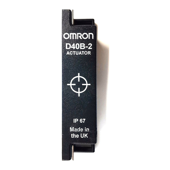
Compact Non-contact Door Switch
D40B
Detects the open/
closed state of doors
without making
contact and has high
resistance to the
environment.
• Detects the open/closed state of doors
without making contact by combining a
special magnetic actuator and switch.
The switching mechanism is not easily
disabled.
• The non-contact operation prevents
the creation of particles due to abra-
sion.
• The actuator and switch can be
washed in water. There are no key-
holes where dirt can accumulate, mak-
ing it easy to keep machinery clean.
• Small distortions in the door and me-
chanical discrepancies can be ab-
sorbed in the allowable operating range
of the magnetic actuator and switch.
• Conforms to Category 3.
Model Number Structure
Model Number Legend
Sensor
D40B-@@@@
1 2 3 4
1. Type
1: Standard Sensor
2: Elongated Sensor
3: High-temperature Type Sensor
2. Auxiliary Output
B: None
D: 1 NC
E: 1 NO
3. Cable Length
3:
3 m
5:
5 m
10:
10 m
4. Wiring Method
None: Pre-wired
C:
Connector (switch side only)
F3SL
Controller
D40B-J@
1
1. Type
1: One main contact + one auxiliary contact (See note.)
2: Two main contacts + one auxiliary contact (See note.)
Note: The auxiliary contacts use non-safety output.
G-197
Advertisement
Table of Contents

Related Manuals for Omron D40B


Summary of Contents for Omron D40B
- Page 1 Compact Non-contact Door Switch D40B Detects the open/ closed state of doors without making contact and has high resistance to the environment. • Detects the open/closed state of doors without making contact by combining a special magnetic actuator and switch.
-
Page 2: Ordering Information
Ordering Information List of Models Sensors (Switches/Actuators) Classification Shape Auxiliary output Cable length Model Standard Sensor None D40B-1B3 10 m D40B-1B10 1 NC D40B-1D3 W × H × D: 48 × 25 × 12 10 m D40B-1D10 Elongated Sensor None... -
Page 3: Specifications
230 VAC, 100 mA, cosφ = 1 250 VAC, 4 A, cosφ = 1 (See note.) 24 VDC, 100 mA, cosφ = 1 30 VDC, 2 A, cosφ = 1 Note: D40B-J1: MOS output; D40B-J2: Contact output. Characteristics Item Type D40B-J1... -
Page 4: Internal Connection Diagram
• EN standards certified by TÜV Nord EN954-1 EN/IEC60204-1 EN/IEC60947-5-3 • UL508, CSA C22.2 No. 14 • EN1088 conformance Internal Connection Diagram D40B-J1 D40B-J2 Control circuit Control circuit output − Note: 1. If a 100/230 VAC power supply is used, connect it to the A1 and A2 terminals. - Page 5 Dimensions Note: All units are in millimeters unless otherwise indicated. Sensor (Switch/Actuator) Standard Sensor Target mark Target mark D40B-1B3 D40B-1B10 D40B-1D3 D40B-1D10 Two, 4.2 dia. Two, 4.2 dia. Cable diameter: 4.2 dia. (Switch) (Actuator) Elongated Sensor D40B-2B3 D40B-2B10 D40B-2D3 D40B-2D10...
-
Page 6: Application Examples
A1 + X1 2 1 13 23 31 POWER (Green) OUTPUT (Green) − X2 3 4 14 24 Application Examples Wiring Example for 1 Sensor and 2 Contactors (with D40B-J1): Auto-reset The configuration in this example is for auto-reset and contactor monitoring. Fuse Blue*... - Page 7 Wiring Example for 1 Sensor and 2 Contactors (with D40B-J2): Auto-reset The configuration in this example is for auto-reset and contactor monitoring. Fuse Blue* Guard door Yellow* Operation Flowchart 2 1 A1 + 13 23 Switch: NO contact D40B-J2 Controller Switch: NC contact 3 4 A2 −...
- Page 8 White* Black* Black* Blue * Auxiliary output * Auxiliary output D40B-1D@ (Standard D40B-1D@ (Standard models) and D40B-2D@ Green models) and D40B-2D@ (Elongated models) only (Elongated models) only − X2 3 4 14 24 X1 21 13 X2 22 14 D40B-J2...
-
Page 9: Safety Precautions
Fuse Replacement Method supplies with large ripples or power supplies that intermittently (D40B-J2 Only) generate incorrect voltages. Note: The D40B-J1 has an automatic recovery mechanism and so fuse • Capacitors are consumable and require regular maintenance and replacement is not necessary. inspection. - Page 10 Solvents Ensure that solvents, such as alcohol, thinner, trichloroethane, or gasoline do not adhere to the product. Solvents may cause markings to fade and components to deteriorate. Installation Location Do not install the product in the following locations. Doing so may result in product failure or malfunction.