Vulcan-Hart VG30 Service Manual
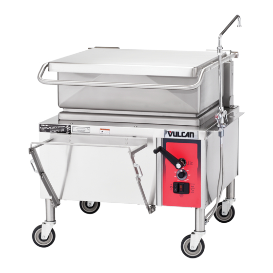
Gas braising pans (30 & 40 gallon)
Hide thumbs
Also See for VG30:
- Installation & operation manual (48 pages) ,
- Specifications (2 pages) ,
- Replacement parts manual (25 pages)
Table of Contents
Advertisement
VG40 SHOWN
This Manual is prepared for the use of trained Vulcan Service
Technicians and should not be used by those not properly
qualified. If you have attended a Vulcan Service School for this
product, you may be qualified to perform all the procedures
described in this manual.
This manual is not intended to be all encompassing. If you have
not attended a Vulcan Service School for this product, you should
read, in its entirety, the repair procedure you wish to perform to
determine if you have the necessary tools, instruments and skills
required to perform the procedure. Procedures for which you do
not have the necessary tools, instruments and skills should be
performed by a trained Vulcan Service Technician.
Reproduction or other use of this Manual, without the express
written consent of Vulcan, is prohibited.
For additional information on Vulcan-Hart Company or to locate an authorized parts
and service provider in your area, visit our website at www.vulcanhart.com.
A product of VULCAN-HART
SERVICE MANUAL
GAS BRAISING PANS
(30 & 40 GALLON)
- NOTICE -
VG30
ML-126847
VG40
ML-126848
LOUISVILLE, KY 40201-0696
F25121(February 2003)
Advertisement
Table of Contents

Related Manuals for Vulcan-Hart VG30


Summary of Contents for Vulcan-Hart VG30
- Page 1 Reproduction or other use of this Manual, without the express written consent of Vulcan, is prohibited. For additional information on Vulcan-Hart Company or to locate an authorized parts and service provider in your area, visit our website at www.vulcanhart.com. A product of VULCAN-HART...
-
Page 2: Table Of Contents
CONDENSED SPARE PARTS LIST ............32 © VULCAN 2003... -
Page 3: General
90,000 90,000 VG40 120,000 120,000 GENERAL Model Designations VG30 - 30 gallon capacity VG40 - 40 gallons capacity Standard Standard set of hand tools. VOM with an AC current tester and DC micro amp current tester capable of measuring 0-10 micro amps. -
Page 4: Removal And Replacement Of Parts
REMOVAL AND REPLACEMENT OF PARTS COVERS AND PANELS WARNING: DISCONNECT THE ELECTRICAL POWER TO THE MACHINE AND FOLLOW LOCKOUT / TAGOUT PROCEDURES. Front, Rear & Side Panels Lift up on the bottom edge of panel until it clears the catch. Tilt outwards and allow the panel to drop down. -
Page 5: Power Supply Box Components
Pull temperature dial from potentiometer shaft and remove mounting nut. Control panel is removed. 10. To install. Align tab on potentiometer with positioning bracket on panel. Install mounting nut and tighten. Adjust stop nut on potentiometer body (as necessary) to ensure a water tight seal on mounting nut. -
Page 6: Pan Position/Down Limit Switch
Pull temperature dial from potentiometer shaft and remove mounting nut. To install: Align tab on potentiometer with positioning bracket on panel. Install mounting nut and tighten. Adjust stop nut on potentiometer body (as necessary) to ensure a water tight seal on mounting nut. - Page 7 NOTE: When installing, replace the o-ring seal (provided) inside the brass fitting and re-use conduit elbow assembly. To install: Position the switch with the head pointing toward installer and gear cam pointing up. NOTE: The plunger on the head is spring loaded and will push the head away from switch body when the last screw is removed.
-
Page 8: Thermocouple Probe
Verify roller arm position on switch. Measure the distance from the rear of the switch body to the center of the roller. The distance should be 3". If distance is ok, proceed to step 7. If distance is not ok, adjust the roller arm position (as necessary) to obtain the 3"... -
Page 9: Dc Lift Motor
Loosen the strain relief nut and the hold down clamps for the motors' power cable. Pull the cable thru the strain relief opening and remove the cable form underneath the clamps. VG30 REAR VIEW SHOWN Remove motor mounting bolts from gear reducer flange. Remove motor from gear reducer. -
Page 10: Gear Reducer
To install: With drive key on shaft, install motor to gear reducer. Route and secure the motors' power cable and re-connect motor lead wires. Replace power supply box cover and side panels. Check for proper operation. GEAR REDUCER WARNING: DISCONNECT THE ELECTRICAL POWER TO THE MACHINE AND FOLLOW LOCKOUT / TAGOUT PROCEDURES. -
Page 11: Gas Combination Valve
NOTE: On the bottom lift arm bushing, the bushing head must be positioned between the lift arm and the crank assembly to create approximately 1/32" spacing. Reverse procedure from step 5 to complete the installation. 10. Check for proper operation. GAS COMBINATION VALVE WARNING: DISCONNECT THE ELECTRICAL POWER TO THE... -
Page 12: Pilot Burner
10. Check for proper operation. PILOT BURNER WARNING: DISCONNECT THE ELECTRICAL POWER TO THE MACHINE AND FOLLOW LOCKOUT / TAGOUT PROCEDURES. WARNING: SHUT OFF THE GAS SUPPLY BEFORE SERVICING THE UNIT. WARNING: ALL GAS JOINTS DISTURBED DURING SERVICING MUST BE CHECKED FOR LEAKS. -
Page 13: Main Burners
NOTE: Runner tube slides onto the gas orifice. When installing, ensure runner tube is fully seated onto gas orifice. To remove gas orifice for inspection or cleaning, disconnect the gas supply tube compression fitting at the manifold. Remove gas orifice from elbow fitting. CAUTION: If orifice is clogged with debris, clean with air or non-flammable liquid only. - Page 14 Slowly release downwards force to remove spring tension. Rotate lid spring lock nut to the next hole position then replace locking pin. Continue until all spring tension is removed, one position at a time. Remove bolts securing the inside lid bearing housing to the lid support bracket.
-
Page 15: Service Procedures And Adjustments
SERVICE PROCEDURES AND ADJUSTMENTS WARNING: CERTAIN PROCEDURES IN THIS SECTION REQUIRE ELECTRICAL TEST OR MEASUREMENTS WHILE POWER IS APPLIED TO THE MACHINE. EXERCISE EXTREME CAUTION AT ALL TIMES. IF TEST POINTS ARE NOT EASILY ACCESSIBLE, DISCONNECT POWER AND FOLLOW LOCKOUT / TAGOUT PROCEDURES, ATTACH TEST EQUIPMENT AND REAPPLY POWER TO TEST. -
Page 16: Temperature Controller Test
12. Repeat the average temperature calculation for up to three attempts. Allow the pan to cycle at least two times between adjustments before performing the calculation. 13. If calibration is unsuccessful, the controller may be malfunctioning and cannot be adjusted properly. -
Page 17: Spark Ignition Test
SPARK IGNITION TEST If the ignition control module is not generating a spark or the spark is not sufficient to light pilot burner, perform the following test. Lower the pan to the full down position, turn the on/off switch on and set the temperature dial to call for heat. -
Page 18: Pilot Burner Flame Adjustment
11. Turn on/off switch on and set the temperature dial to call for heat. 12. Manually operate pan position/down limit switch and observe spark from ignitor. If spark from ignitor is present and lights the gas for pilot burner, and pilot burner remains lit, then the system is working properly. -
Page 19: Flame Sense Current Test
10. Manually operate pan position/down limit switch and observe pilot burner flame. To increase pilot flame, turn the screw counterclockwise. To decrease pilot flame, turn the screw clockwise. 11. Once the pilot flame has been adjusted correctly, release the pan position /down limit switch , turn the on/off switch off and replace the adjustment screw cap. -
Page 20: Gas Manifold Pressure Adjustment
Ignition control module is energized and trial for ignition starts (90 seconds). Verify 24VAC between terminals 5 & 6. If voltage is not present, see schematic diagram. Pilot valve (PV) contacts close to energize the pilot valve coil, allowing gas flow to the pilot burner. -
Page 21: Main Burners
NOTE: Accurate gas pressure adjustments can only be made with the gas on and the main burners lit. Set pressure as listed in gas pressure table. 10. Once the correct pressure has been set, turn the on/off switch off, replace the adjustment screw cap and pipe plug. -
Page 22: Dc Motor Controller Test
DC MOTOR CONTROLLER TEST Lower the pan to the full down position. Raise the lid to the full open position. Access the DC motor controller as outlined under POWER SUPPLY BOX COMPONENTS in REMOVAL AND REPLACEMENT OF PARTS. Set VOM to measure AC volts and connect meter leads at L1 &... -
Page 23: Lid Spring Tension Adjustment
If main burners do not light, verify 24VAC input to the switch, and that the voltage is output from the switch. If voltage is present on the output side of the switch, the switch is functioning properly. If voltage is not present, install a replacement pan position/down limit switch and repeat this procedure to adjust. - Page 24 To adjust: Place a 1 5/8" wrench on the lid spring lock nut and apply a downward force until locking pin can be removed. Continue to hold lock nut in place. CAUTION: Do not release wrench while locking pin is removed or damage to the braising pan may occur.
-
Page 25: Electrical Operation
ELECTRICAL OPERATION COMPONENT FUNCTION Temperature Controller ..Monitors thermocouple input (type E) and regulates braising pan temperature. An external set point potentiometer is used for temperature adjustments. Transformer ... . . Supplies 24VAC for heating circuit. If motorized pan lift option is installed, supplies 24VAC for lift control circuit. -
Page 26: Component Location
GAS BRAISING PANS - ELECTRICAL OPERATION COMPONENT LOCATION F25121 (February 2003) Page 26 of 32... -
Page 27: Ignition Control Module
GAS BRAISING PANS - ELECTRICAL OPERATION IGNITION CONTROL MODULE The ignition control module is energized when 24 volts is applied between terminals 5 & 6. The module outputs 24 volts from terminals 2 & 3 to the pilot valve coil (PV) on the gas combination valve, allowing gas flow to the pilot burner. -
Page 28: Sequence Of Operation
SEQUENCE OF OPERATION Refer to schematic diagram AI1341 for the electrical sequence of operation. Manual pan lift is the standard configuration. Heating Conditions. 120VAC to braising pan, polarity is correct, and is properly grounded. Temperature controller energized. 24VAC transformer energized. Temperature dial at lowest setting (potentiometer fully CCW). - Page 29 Pan reaches full tilt position, the up limit switch N.C. contacts open and K1 relay coil is de- energized. The three sets of K1 contacts return to N.O. position. Power is removed from the DC motor controller, the DC lift motor and pan travel stops.
-
Page 30: Schematic Diagram
GAS BRAISING PANS - ELECTRICAL OPERATION SCHEMATIC DIAGRAM F25121 (February 2003) Page 30 of 32... -
Page 31: Troubleshooting
TROUBLESHOOTING GAS HEATING (MANUAL LIFT OR MOTORIZED LIFT OPTION) SYMPTOMS No spark to ignite pilot burner gas, power on light is lit. Spark at ignitor but pilot burner does not light. Pilot burner lights but will not maintain flame. Main burner(s) do not light or will not maintain flame. -
Page 32: Motorized Lift Option Only
Lift control switch malfunction (momentary on - lower). Down limit switch malfunction. K2 relay malfunction. DC motor controller - Fuses open or controller malfunction. DC Lift motor inoperative. 10. Gear reducer malfunction. VG30 & VG40 GAS BRAISING PANS DESCRIPTION DESCRIPTION NOTE NOTE Printed in U.S.A.