Table of Contents
Advertisement
Quick Links
Download this manual
See also:
Service & Parts Manual
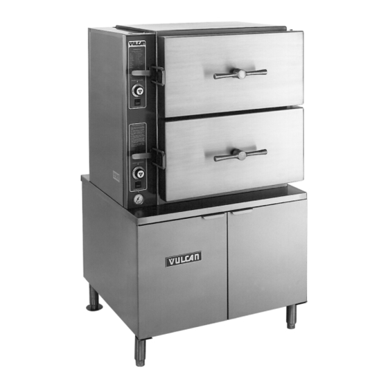
VL2GPS SHOWN
This Manual is prepared for the use of trained Vulcan Service
Technicians and should not be used by those not properly
qualified. If you have attended a Vulcan Service School for this
product, you may be qualified to perform all the procedures
described in this manual.
This manual is not intended to be all encompassing. If you have
not attended a Vulcan Service School for this product, you should
read, in its entirety, the repair procedure you wish to perform to
determine if you have the necessary tools, instruments and skills
required to perform the procedure. Procedures for which you do
not have the necessary tools, instruments and skills should be
performed by a trained Vulcan Service Technician.
Reproduction or other use of this Manual, without the express
written consent of Vulcan, is prohibited.
A product of VULCAN-HART
Form 24650 (May 1999)
SERVICE MANUAL
VL BOILER BASE SERIES
CONVECTION STEAMERS
(GAS, ELECTRIC, DIRECT AND REGENERATED)
VL2GPS
ML-52391
VL2GMS
ML-52388
VL2GAS
ML-52390
VL2GSS
ML-52389
VL3GPS
ML-52395
VL3GMS
ML-52392
VL3GAS
ML-52394
VL3GSS
ML-52393
VL2EPS
ML-52741
VL2EMS
ML-52742
VL2EAS
ML-52743
VL2ESS
ML-52744
VL3EPS
ML-52745
VL3EMS
ML-52746
VL3EAS
ML-52747
VL3ESS
ML-52748
- NOTICE -
VL2DPS
ML-52749
VL2DMS
ML-52750
VL2DAS
ML-52751
VL2DSS
ML-52752
VL3DPS
ML-52753
VL3DMS
ML-52754
VL3DAS
ML-52755
VL3DSS
ML-52756
VL2RPS
ML-52757
VL2RMS
ML-52758
VL2RAS
ML-52759
VL2RSS
ML-52760
VL3RPS
ML-52761
VL3RMS
ML-52762
VL3RAS
ML-52763
VL3RSS
ML-52764
LOUISVILLE, KY 40201-0696
Advertisement
Table of Contents

Related Manuals for Vulcan-Hart VL2EAS


Summary of Contents for Vulcan-Hart VL2EAS
- Page 1 VL2GPS SHOWN This Manual is prepared for the use of trained Vulcan Service Technicians and should not be used by those not properly qualified. If you have attended a Vulcan Service School for this product, you may be qualified to perform all the procedures described in this manual.
-
Page 2: Table Of Contents
TABLE OF CONTENTS GENERAL ................4 Introduction . - Page 3 TROUBLESHOOTING ..............84 © VULCAN 1999...
-
Page 4: General
Large Capacity Pressure Steamer Vulcan GENERAL Boiler Code Descriptions Vulcan-Hart incorporates redundant controls in compliance with California Code (Cal-Code) and CSD-1 as an option on steam equipment when required by state and/or local building code requirements. Descriptions of the codes are listed below. -
Page 5: Tools
Vulcan recommends the water contain less than 60ppm of “total dissolved solids” (TDS) and have a PH factor between 7 to 8. These water properties can be achieved by using a properly maintained water softener. -
Page 6: Gas Steamers
200,000 200,000 VL3GSS 240,000 240,000 Electric Steamers 1 PHASE 3 PHASE TOTAL MODEL 208V 240V 208V 240V 480V 220/380V & 240/415V VL2EPS VL2EMS VL2ESS VL2EAS *std LINE PRESSURE (INCHES W.C.) NATURAL PROP. RECOMMEND 10.0 10.0 10.0 10.0 10.0 10.0 10.0 10.0... -
Page 7: Steamer Operation
STEAMER OPERATION Ensure that all utility connections to the steamer have been made and are turned on. On models that are CSD-1 equipped, amber colored lights for hi pressure and low water level will illuminate and stay on until the boiler is full and the manual reset switch pressed. -
Page 8: Direct Steam Powered Cooker
Observe water level gauge glass to verify that water is in boiler and that the level in the gauge glass is about half full. Both valves on the gauge glass assembly must be open to fill the gauge. When the water reaches the minimum level, the steam solenoid valve will open, allowing steam to enter the steam coil in the heat exchanger tank and begin heating the water. - Page 9 Standard Set the timer to the desired cooking time. The timer must be set past five minutes to change the state of the timer control micro switch contacts. If preheating is desired, allow five to ten minutes (recommended) of additional time at the beginning of the cook cycle.
- Page 10 Prevent Set the timer to the desired cooking time. The timer must be set past five minutes to change the state of the timer control micro switch contacts. Pull the steam control arm handle forward and lock it by pulling the handle down. This opens the steam inlet gate valve, allowing steam to enter the compartment.
-
Page 11: Component Function
CABINET BASE BOILER CONTROLS Water Level Gauge Assembly ....Permits a visual confirmation the water level is being maintained in Water Level Control and Level Sensing Probes ... These controls allow water to enter the boiler to fill and maintain the Boiler Fill Solenoid Valve . - Page 12 Handhole Cover Assembly ..When unbolted and removed, allows internal examination and cleaning Boiler Pressure Gauge ..Indicates the amount of steam pressure in the boiler. Check Valve .
-
Page 13: Cooking Compartment Controls
COOKING COMPARTMENT CONTROLS The top half of the steamer consists of two to three separate cooking compartments depending on the model. Each compartment functions independently with its own set of controls. Power is supplied to the controls through the compartment power switch and the cooking timer control micro switch contacts. Prevent and Automatic models have a load compensating thermal switch that prevents the controls from receiving power until the compartment reaches 180°F to close the switch. -
Page 14: Removal And Replacement Of Parts
VL SERIES STEAMERS - REMOVAL AND REPLACEMENT OF PARTS REMOVAL AND REPLACEMENT OF PARTS COMPONENT LOCATIONS Page 14 of 88... - Page 15 VL SERIES STEAMERS - REMOVAL AND REPLACEMENT OF PARTS Page 15 of 88...
- Page 16 COOKING COMPARTMENT CONTROLS - COMPONENT CONFIGURATIONS 1. Prevent thermal switch, inlet steam gate valve, steam exhaust solenoid (shown above) valve, steam control arm solenoid, timer, buzzer and power switch with light. Does not use a steam trap. 2. Automatic same as prevent except does not include steam exhaust solenoid valve but does include an exhaust steam gate valve and two steam traps.
-
Page 17: Water Level Controls - Low Level Cut Off And Differential
WATER LEVEL CONTROLS - LOW LEVEL CUT OFF AND DIFFERENTIAL WARNING: DISCONNECT THE ELECTRICAL POWER TO THE MACHINE AT THE MAIN CIRCUIT BOX. PLACE A TAG ON THE CIRCUIT BOX INDICATING THE CIRCUIT IS BEING SERVICED. Solid State Open the cabinet base doors. Remove the two screws at the top of the boiler control box and allow cover to drop down. -
Page 18: Boiler Assembly
BOILER ASSEMBLY WARNING: DISCONNECT THE ELECTRICAL POWER TO THE MACHINE AT THE MAIN CIRCUIT BOX. PLACE A TAG ON THE CIRCUIT BOX INDICATING THE CIRCUIT IS BEING SERVICED. WARNING: SHUT OFF THE GAS BEFORE SERVICING THE UNIT. WARNING: ALL GAS JOINTS DISTURBED DURING SERVICING MUST BE CHECKED FOR LEAKS. -
Page 19: Boiler Fill And Cold Water Condenser Solenoid Valves
BOILER FILL AND COLD WATER CONDENSER SOLENOID VALVES WARNING: DISCONNECT THE ELECTRICAL POWER TO THE MACHINE AT THE MAIN CIRCUIT BOX. PLACE A TAG ON THE CIRCUIT BOX INDICATING THE CIRCUIT IS BEING SERVICED. Turn off the water supply to the steamer. Open the cabinet base doors and remove the two screws at the top of the boiler control box and allow cover to drop down. -
Page 20: Compartment Gasket And Door Screw Nut, Door And Bushings
COMPARTMENT GASKET AND DOOR SCREW NUT, DOOR AND BUSHINGS Gasket Open the compartment door to be replaced. Remove screws securing the gasket retaining plate to the gasket. Lift the gasket off the inner door plate. Position the new gasket on the inner door plate and reverse procedure to install. -
Page 21: Heater Contactors
HEATER CONTACTORS WARNING: DISCONNECT THE ELECTRICAL POWER TO THE MACHINE AT THE MAIN CIRCUIT BOX. PLACE A TAG ON THE CIRCUIT BOX INDICATING THE CIRCUIT IS BEING SERVICED. Open the cabinet base doors, remove the two screws from the contactor box cover and lift cover off. -
Page 22: Service Procedures And Adjustments
SERVICE PROCEDURES AND ADJUSTMENTS WARNING: CERTAIN PROCEDURES IN THIS SECTION REQUIRES ELECTRICAL TEST OR MEASUREMENTS WHILE POWER IS APPLIED TO THE MACHINE. EXERCISE EXTREME CAUTION AT ALL TIMES. IF TEST POINTS ARE NOT EASILY ACCESSIBLE, DISCONNECT POWER, ATTACH TEST EQUIPMENT AND REAPPLY POWER TO TEST. BOILER Inspection It is recommended the boiler be inspected for... -
Page 23: Deliming Only (Models With Deliming Port Assembly)
10. Cooking compartment timers are to be in the OFF position. Turn the boiler switch ON and open water valve if necessary. 11. Boiler is to operate under pressure for 90 minutes or per the instructions for the chemical in use. 12. -
Page 24: Water Level Control(S) Test
WATER LEVEL CONTROL(S) TEST Loose electrical connections may prevent the heat from coming on or may cause the boiler to overfill. An accumulation of lime scale on or near the water level sensing probes may cause them to retain water (moist) on the probe surface and give a false reading. -
Page 25: Cycling And High Limit Pressure Switches
With the boiler empty, check the voltage across terminals 9 & 10. Meter should read 300 to 350VAC. If voltage is correct proceed to step 3. If voltage reading is approximately 30VAC then the internal contactor is energized but the probes are scaled over and moist and/or have a damaged insulator giving a false reading. -
Page 26: Fill And Cold Water Solenoid Valves
Two slotted and square headed adjustment screws extend through the top of the switch case. A pressure scale and indicating pointers are visible through the sight glass window to indicate the approximate pressure setting. The adjustment screw directly above the right side pointer changes the cut-out (off) set point and the adjustment screw directly above the left side pointer changes cut-in (on) set point. -
Page 27: High Limit Thermostat
HIGH LIMIT THERMOSTAT WARNING: DISCONNECT THE ELECTRICAL POWER TO THE MACHINE AT THE MAIN CIRCUIT BOX. PLACE A TAG ON THE CIRCUIT BOX INDICATING THE CIRCUIT IS BEING SERVICED. Remove thermostat (bi-metallic disk type) as outlined under “HIGH LIMIT THERMOSTAT” in “REMOVAL AND REPLACEMENT OF PARTS”. -
Page 28: Boiler Slow To Pressurize
If the blowdown operation appears to function sluggishly or not at all, considerable scalants may be lodged in the drain pipe and/or the valve. Disconnect the valve from the drain line and inspect both the valve and the drain pipe fixed to the boiler. If considerable scalants or lime build up is apparent, then not only the valve, but also the boiler and water level probes must be thoroughly cleaned. -
Page 29: Inlet Water Strainer
Gas burner ports clogged or obstruction around air shutter. After a period of time, gas burners can accumulate carbon in their ports or become clogged by food and grease debris from kitchen cleaning, restricting performance. To clean burners, remove them from burner box and boil in water for 10 -15 minutes to dislodge clog. - Page 30 NOTE: If adjustments in gas or pilot pressure settings are made, always replace the adjustment cover screw to assure proper gas control operation. If the adjustment does not result in a pilot flame of proper size, then gas might not be flowing properly to the pilot.
-
Page 31: Gas Burners
With the thermocouple disconnected, connect the meter leads to the tube and threaded end. Turn the power switch ON and light the pilot. Hold down the OFF/PILOT/ON knob and allow the pilot to heat the thermocouple for one to two minutes. - Page 32 Once the pilot flame is confirmed, a 24 volt output from terminal one will be sent, allowing the main valve (cycling) coil of the combination valve to operate at the request of the cycling pressure switch. Terminals: Main Valve - 24VAC will be present on terminal #1 with the pilot sensing electrode sensing an adequate pilot fame.
-
Page 33: Gas Manifold Pressure Adjustment
If a spark from ignitor is present but does not ignite gas before the ignition control module locks out, (90 sec.) there may not be enough gas in the line for ignition. Verify the gas supply and gas combination control valve are both on. -
Page 34: Direct Steam Models
Once the correct pressure has been set, turn the power switch OFF, replace the adjustment screw cap and 1/8 inch NPT plug (pressure tap) on the outlet side of the valve. Check for proper operation. DIRECT STEAM MODELS These models consist of a pressure regulator and gauge that run off a buildings potable steam supply. - Page 35 NUMBER TOTAL VOLTAGE ELEMENTS *220/380 240/415 *220/380 240/415 *220/380 240/415 *220/380 240/415 NOTES: Values in the table are nominal. Tolerance is +/-10 %. Asterisk (*) indicates 3 phase/4wire. Each heater has three internal elements. AMPERAGE RESISTANCE PER LINE ELEMENT 1 PH 3 PH 10.5 Page 35 of 88...
-
Page 36: Thermal Switch - Prevent And Automatic Models
THERMAL SWITCH - PREVENT AND AUTOMATIC MODELS The load compensator is a thermal switch in a stainless steel housing that screws into a 3/8 NPT fitting (newer models) on the left side wall of the compartment. The switch contacts should close when the compartment temperature reaches 180 F, supplying power to the steam exhaust solenoid valve, pilot light and cooking timer motor. -
Page 37: Steam Gate Valve(S)
STEAM GATE VALVE(S) On all models, each cooking compartment has its own mechanical steam gate valve that supplies steam to the cooking compartment when the steam control arm handle is pulled forward. The Prevent models use a solenoid valve to exhaust steam from the compartment whereas the Automatic, Standard and Manual models use an additional steam gate valve to exhaust steam when the steam control arm... -
Page 38: Electrical Operation
ELECTRICAL OPERATION WATER LEVEL CONTROLS Solid State - Low level Cut-Off & Differential Control The steamer is equipped with three water level sensing probes (high, low and low level cut-off) and a single water level control board. The water level control board performs two functions: Provide low level cut-off protection to shut off the heat source in case the water level drops... - Page 39 Solid State - Auxiliary Low Level Cut-Off This control serves as a safety backup to the main water level control (WLC) board to meet Cal-Code and CSD-1 code requirements. The auxiliary control provides auxiliary low level cut-off protection to shut off the heat source in case the water level drops below the low level cut-off (LLCO) probe.
-
Page 40: Electro Mechanical - Low Level Cut-Off & Differential Control
Electro Mechanical - Low level Cut-Off & Differential Control The steamer is equipped with three water level sensing probes (high, low and low level cut-off), a differential level control (1G1GO) and a low level cut-off control (1D1DO). The low-level cut-off is an additional control that is identical to the differential level control but serves as the safety backup to shut off the heat source in case the water level drops... - Page 41 VL SERIES STEAMER - ELECTRICAL OPERATION Electro Mechanical - Auxiliary Low Level Cut-Off This control serves as a safety backup to the main low level cut-off (LLCO) control to meet Cal-Code requirements. The operation of the auxiliary control is identical to the main low level cut-off control but performs a single function: 1) Provide auxiliary low level cut-off protection to shut off the heat source in case the water level drops below the low level cut-off (LLCO) probe.
-
Page 42: Sequence Of Operation
SEQUENCE OF OPERATION GAS MODELS This sequence of operation is written for steamers with electronic ignition, solid state water level controls, CSD-1 (code) boiler controls option and with Prevent cooking compartment controls. Refer to schematic diagram numbers 3928 and 3929 for a boiler control schematic and 3962 for a schematic and wiring diagram on Prevent cooking compartment controls. - Page 43 Water level reaches LLCO (low water level cut- off) probe for the water level control and to the auxiliary LLCO probe for the auxiliary low level cut-off control. Power to terminal 9 on the water level control. LLCO relay energizes, LLCO-2 (N.O.) contacts close and LED lights.
- Page 44 Cook Cycle A Cook cycle should not be started, until the initial fill and preheat is completed, in order for the boiler steam pressure to be within operational limits. Insert product into steamer. Compartment door is closed and screw handle tightened down. Compartment steam control arm is pulled forward and latches, allowing steam to enter compartment.
-
Page 45: Electric Models
HL-3 opens. Fill solenoid de-energized and water stops flowing into tank. HL LED goes out. The water refill cycle will occur whenever the water level is below the low level probe and will not affect the operation of either the preheat or cook cycle. - Page 46 NOTE: Power the internal contactors on the low level cut-off and auxiliary low level cut-off will remain, until the water level drops below the LLCO probes or the power switch is turned OFF. Manual reset switch is pressed (momentary). The auxiliary heater contactor is energized supplying power to the heating elements and the heat light (amber) comes on.
- Page 47 Once compartment temperature reaches approximately 180°F thermal switch closes and supplies power L1 (HOT) to: Steam exhaust solenoid valve (N.O.) energized and closes. NOTE: Even though steam exhaust solenoid valve is closed, a small opening exists in the “guillotine” blade of the valve to allow “limited free venting”...
- Page 48 VL SERIES STEAMER - ELECTRICAL OPERATION PAGE PURPOSELY LEFT BLANK Page 48 of 88...
-
Page 49: Schematics, Gas Steamers, Boiler Controls Vl2G And Vl3G - Prevent, Automatic, Standard And Manual
VL SERIES STEAMER - ELECTRICAL OPERATION SCHEMATICS, GAS STEAMERS, BOILER CONTROLS VL2G AND VL3G - PREVENT, AUTOMATIC, STANDARD AND MANUAL Manual Ignition, Standard Controls Page 49 of 88... -
Page 50: Electronic Ignition, Standard Controls
VL SERIES STEAMER - ELECTRICAL OPERATION Electronic Ignition, Standard Controls Page 50 of 88... -
Page 51: Manual Ignition, Csd-1 Code Controls
VL SERIES STEAMER - ELECTRICAL OPERATION Manual Ignition, CSD-1 Code Controls Page 51 of 88... -
Page 52: Electronic Ignition, Csd-1 Code Controls
VL SERIES STEAMER - ELECTRICAL OPERATION Electronic Ignition, CSD-1 Code Controls Page 52 of 88... - Page 53 VL SERIES STEAMER - ELECTRICAL OPERATION Page 53 of 88...
-
Page 54: Wiring Diagrams, Gas Steamers, Boiler Controls Vl2G And Vl3G - Prevent, Automatic, Standard And Manual
VL SERIES STEAMER - ELECTRICAL OPERATION WIRING DIAGRAMS, GAS STEAMERS, BOILER CONTROLS VL2G AND VL3G - PREVENT, AUTOMATIC, STANDARD AND MANUAL Manual Ignition, Standard Controls Page 54 of 88... - Page 55 VL SERIES STEAMER - ELECTRICAL OPERATION Page 55 of 88...
-
Page 56: Electronic Ignition, Standard Controls
VL SERIES STEAMER - ELECTRICAL OPERATION Electronic Ignition, Standard Controls Page 56 of 88... - Page 57 VL SERIES STEAMER - ELECTRICAL OPERATION Page 57 of 88...
-
Page 58: Manual Ignition, Csd-1 Code Controls
VL SERIES STEAMER - ELECTRICAL OPERATION Manual Ignition, CSD-1 Code Controls Page 58 of 88... - Page 59 VL SERIES STEAMER - ELECTRICAL OPERATION Page 59 of 88...
-
Page 60: Electronic Ignition, Csd-1 Code Controls
VL SERIES STEAMER - ELECTRICAL OPERATION Electronic Ignition, CSD-1 Code Controls Page 60 of 88... - Page 61 VL SERIES STEAMER - ELECTRICAL OPERATION Page 61 of 88...
-
Page 62: Schematics, Electric Steamers, Boiler Controls Vl2E And Vl3E - Prevent, Automatic, Standard And Manual
VL SERIES STEAMER - ELECTRICAL OPERATION SCHEMATICS, ELECTRIC STEAMERS, BOILER CONTROLS VL2E AND VL3E - PREVENT, AUTOMATIC, STANDARD AND MANUAL Auto Blowdown, Standard Controls Page 62 of 88... -
Page 63: Auto Blowdown, Cal-Code Controls
VL SERIES STEAMER - ELECTRICAL OPERATION Auto Blowdown, Cal-Code Controls Page 63 of 88... -
Page 64: Wiring Diagrams, Electric Steamers, Boiler Controls Vl2E And Vl3E - Prevent, Automatic, Standard And Manual
VL SERIES STEAMER - ELECTRICAL OPERATION WIRING DIAGRAMS, ELECTRIC STEAMERS, BOILER CONTROLS VL2E AND VL3E - PREVENT, AUTOMATIC, STANDARD AND MANUAL Auto Blowdown, Standard Controls (contactor - 1 std.) Page 64 of 88... - Page 65 VL SERIES STEAMER - ELECTRICAL OPERATION Page 65 of 88...
-
Page 66: Auto Blowdown, Standard Controls (Contactors - 2 Std.)
VL SERIES STEAMER - ELECTRICAL OPERATION Auto Blowdown, Standard Controls (contactors - 2 std.) Page 66 of 88... - Page 67 VL SERIES STEAMER - ELECTRICAL OPERATION Page 67 of 88...
-
Page 68: Manual Blowdown, Cal-Code Controls (Contactors - 1 Std. 1 Aux.)
VL SERIES STEAMER - ELECTRICAL OPERATION Manual Blowdown, Cal-Code Controls (contactors - 1 std. 1 aux.) Page 68 of 88... - Page 69 VL SERIES STEAMER - ELECTRICAL OPERATION Page 69 of 88...
-
Page 70: Auto Blowdown, Cal-Code Controls ( Contactors - 1 Std. 1 Aux.)
VL SERIES STEAMER - ELECTRICAL OPERATION Auto Blowdown, Cal-Code Controls ( contactors - 1 std. 1 aux.) Page 70 of 88... - Page 71 VL SERIES STEAMER - ELECTRICAL OPERATION Page 71 of 88...
-
Page 72: Auto Blowdown, Cal-Code Controls (Contactors - 2 Std. 2 Aux.)
VL SERIES STEAMER - ELECTRICAL OPERATION Auto Blowdown, Cal-Code Controls (contactors - 2 std. 2 aux.) Page 72 of 88... - Page 73 VL SERIES STEAMER - ELECTRICAL OPERATION Page 73 of 88...
-
Page 74: Manual Blowdown, Cal-Code Controls (Contactors - 2 Std. 2 Aux.)
VL SERIES STEAMER - ELECTRICAL OPERATION Manual Blowdown, Cal-Code Controls (contactors - 2 std. 2 aux.) Page 74 of 88... - Page 75 VL SERIES STEAMER - ELECTRICAL OPERATION Page 75 of 88...
-
Page 76: Wiring Diagrams, Electric Heater Circuits Vl2E And Vl3E - Prevent, Automatic, Standard And Manual
VL SERIES STEAMER - ELECTRICAL OPERATION WIRING DIAGRAMS, ELECTRIC HEATER CIRCUITS VL2E AND VL3E - PREVENT, AUTOMATIC, STANDARD AND MANUAL Standard and Cal-Code/CSD-1 Controls Page 76 of 88... -
Page 77: Schematic And Wiring Diagrams, Direct Steamers, Cabinet Base Vl2D And Vl3D - Prevent, Automatic, Standard And Manual
VL SERIES STEAMER - ELECTRICAL OPERATION SCHEMATIC AND WIRING DIAGRAMS, DIRECT STEAMERS, CABINET BASE VL2D AND VL3D - PREVENT, AUTOMATIC, STANDARD AND MANUAL See “SCHEMATIC AND WIRING DIAGRAMS - COMPARTMENT CONTROLS” Page 77 of 88... -
Page 78: Wiring Diagrams, Regenerated Steamers, Boiler Controls Vl2R And Vl3R - Prevent, Automatic, Standard And Manual
VL SERIES STEAMER - ELECTRICAL OPERATION WIRING DIAGRAMS, REGENERATED STEAMERS, BOILER CONTROLS VL2R AND VL3R - PREVENT, AUTOMATIC, STANDARD AND MANUAL Manual Blowdown (Older Models) Page 78 of 88... - Page 79 VL SERIES STEAMER - ELECTRICAL OPERATION Auto Blowdown (Older Models) Page 79 of 88...
-
Page 80: Schematic And Wiring Diagrams - Compartment Controls
VL SERIES STEAMER - ELECTRICAL OPERATION SCHEMATIC AND WIRING DIAGRAMS - COMPARTMENT CONTROLS Prevent Page 80 of 88... -
Page 81: Automatic
VL SERIES STEAMER - ELECTRICAL OPERATION Automatic Page 81 of 88... -
Page 82: Standard
VL SERIES STEAMER - ELECTRICAL OPERATION Standard Page 82 of 88... -
Page 83: Manual
VL SERIES STEAMER - ELECTRICAL OPERATION Manual NO ELECTRICAL COMPONENTS ARE USED WITH THE MANUAL COMPARTMENT CONTROLS OPTION. THE CONTROLS CONSIST OF A MANUAL COOKING TIMER AND MANUAL STEAM CONTROL ARM TO CLOSE AND OPEN THE STEAM GATE VALVES. Page 83 of 88... -
Page 84: Troubleshooting
WARNING: CERTAIN PROCEDURES IN THIS SECTION REQUIRE ELECTRICAL TESTS OR MEASUREMENTS WHILE POWER IS APPLIED TO THE MACHINE. EXERCISE EXTREME CAUTION AT ALL TIMES. IF TEST POINTS ARE NOT EASILY ACCESSIBLE, DISCONNECT POWER, ATTACH TEST EQUIPMENT AND REAPPLY POWER TO TEST. SYMPTOM Compartment leaks water around door. - Page 85 SYMPTOM Boiler base will not heat or build pressure. Steam output low or slow cooking. Boiler leaks water. Boiler fill solenoid cycling to frequently. Boiler water level too high. Boiler does not fill or slow to fill. POSSIBLE CAUSES Check incoming voltage. Boiler not filled - check fill solenoid for power, clogging or malfunction.
- Page 86 SYMPTOM Cooking timer motor does not run. Buzzer not operating. Compartment red light and timer do not come on; excessive time elapses before they come on; timer stops, the red light goes out, and the buzzer does not sound after compartment exhausts steam; time is set as usual for the product and the product is overcooked.
- Page 87 SYMPTOM Burner won’t light. Burner won’t stay lit. GAS MODELS ONLY POSSIBLE CAUSES Gas not on. Ignition control module reset switch in the OFF position or malfunctioning. Ignition module not receiving power. Check ignition module transformer for 24VAC output to module on automatic ignition systems.
- Page 88 SYMPTOM Pilot not lit or goes out. Spark Ignitor not sparking. Form 24650 (May 1999) POSSIBLE CAUSES Gas not on. Pilot going out due to drafts, excess steam from drain or steamer not level. Improper venting can direct the pilot flame away from thermopile or flame sensor.