Vulcan-Hart VPX3 Service Manual
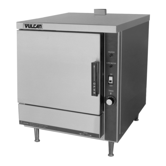
Vpx series electric countertop steamers
Hide thumbs
Also See for VPX3:
- Installation and operation manual (12 pages) ,
- Specifications (2 pages)
Table of Contents
Advertisement
This Manual is prepared for the use of trained Vulcan Service
Technicians and should not be used by those not properly
qualified. If you have attended a Vulcan Service School for this
product, you may be qualified to perform all the procedures
described in this manual.
This manual is not intended to be all encompassing. If you have
not attended a Vulcan Service School for this product, you should
read, in its entirety, the repair procedure you wish to perform to
determine if you have the necessary tools, instruments and skills
required to perform the procedure. Procedures for which you do
not have the necessary tools, instruments and skills should be
performed by a trained Vulcan Service Technician.
Reproduction or other use of this Manual, without the express
written consent of Vulcan-Hart, is prohibited.
A product of VULCAN-HART
SERVICE MANUAL
VPX SERIES
ELECTRIC
COUNTERTOP
STEAMERS
MODEL
- NOTICE -
ML
VPX3
126586
VPX5
126588
LOUISVILLE, KY 40201-0696
F25111 (March 2002)
Advertisement
Table of Contents

Related Manuals for Vulcan-Hart VPX3


Summary of Contents for Vulcan-Hart VPX3
- Page 1 This Manual is prepared for the use of trained Vulcan Service Technicians and should not be used by those not properly qualified. If you have attended a Vulcan Service School for this product, you may be qualified to perform all the procedures described in this manual.
-
Page 2: Table Of Contents
CONDENSED SPARE PARTS LIST ............21 © Vulcan 2002... -
Page 3: General
VPX3 - 3 pan capacity* VPX5 - 5 pan capacity* *based on 2.5 inch pan depth Exterior Dimensions VPX3 - 21"w x 25"d x 25" h* VPX5 - 21"w x 25"d x 31.5" h* *Includes 4" legs and 2" steam vent height SPECIFICATIONS Water Requirements Use "potable"... -
Page 4: Removal And Replacement Of Parts
REMOVAL AND REPLACEMENT OF PARTS COVERS AND PANELS WARNING: DISCONNECT THE ELECTRICAL POWER TO THE MACHINE AT THE MAIN CIRCUIT BOX. PLACE A TAG ON THE CIRCUIT BOX INDICATING THE CIRCUIT IS BEING SERVICED. Right Side Panel 1. Remove screws from bottom of panel. 2. -
Page 5: Timer
4. Reverse procedure to install replacement component and check steamer for proper operation. NOTE: If replacing temperature control, see "TEMPERATURE CONTROL CALIBRATION - ADJUSTMENT FOR ELEVATION" in "SERVICE PROCEDURES AND ADJUSTMENTS". TIMER WARNING: DISCONNECT THE ELECTRICAL POWER TO THE MACHINE AT THE MAIN CIRCUIT BOX. -
Page 6: Temperature Probe
NOTE: Thermostat base is a brass 5/8" hex with a threaded stem. 4. Apply a small amount of "thermal transfer compound" to the mating surface (disk side) of the replacement thermostat. A. Spread the compound completely and evenly over the surface of the thermostat. 5. - Page 7 5. Remove mounting nuts & washers from the rear cooking compartment support legs and remove base. 6. Disconnect heating element lead wires from element terminals. 7. Disconnect high limit thermostat lead wires and remove high limit from heating element assembly. 8.
-
Page 8: Manual Drain Valve
A. Temporarily install a flat washer and nut on all mounting studs. Hand tighten only. B. Tighten each nut to 100 in-lb using the sequence as shown. C. Remove nut and washer from each mounting stud. D. Apply Loctite 271 to heating element assembly mounting stud threads. -
Page 9: Door
5. Remove mounting nuts & washers from the rear cooking compartment support legs and remove base. 6. Remove outer nut on drain valve stem and lift off drain handle assembly. 7. Remove manual drain valve from cooking compartment drain pipe. 8. - Page 10 Gasket 1. Open the door. 2. Remove screws from the gasket plate. 3. Pull the gasket plate out from the door housing and remove the gasket. 4. Position the new gasket on the gasket plate and reverse the procedure to install. Adjust the door as outlined under "DOOR SEALING ADJUSTMENT".
-
Page 11: Service Procedures And Adjustments
Latch Assembly 1. Open the door. 2. Remove screws from the top and bottom of the door. 3. Pull the "inner" door panel out from the door housing with the gasket plate and gasket still attached. 4. Remove the screws from the side edge of the door that secure the latch mechanism and remove the latch from the door. -
Page 12: Door Sealing Adjustment
To adjust: 1. Reinstall the striker with the slot pointing upwards and "hand tighten" nut only. 2. Close the door to center the striker in the oval mounting hole. 3. Open the door and check the strikers’ slot for horizontal alignment. The slot on the striker must be kept horizontal in order for the door latch to catch it properly and latch. -
Page 13: Temperature Control Calibration
AMPS PER KW PER ELEMENT VOLTAGE ELEMENT 1 PH 3 PH 14.4 12.5 24.0 14.0 21.0 12.0 NOTES: 1. Values in the table are nominal. Tolerance is +5/-10%. 2. Voltage values are @ 60HZ. 3. Each heating element assembly contains 3 elements. Total KW would be the individual element KW times 3. -
Page 14: Electrical Operation
ELECTRICAL OPERATION Buzzer ....Signals end of a "cook" cycle when cooking time expires. Contactor ....Supplies line voltage to heating element assembly. Relay R1 . -
Page 15: Sequence Of Operation
SEQUENCE OF OPERATION Wiring diagram 7264 will be used to explain the electrical sequence of operation. Timed Cooking Mode Conditions. Steamer connected to correct voltage and is properly grounded. Cooking mode switch (power) off. High limit thermostat closed. Standby thermostat closed. Temperature control is setup properly and is ready to use. - Page 16 Door closed (door switch closed). Timer "off". Cooking compartment filled to the water level mark and below standby temperature of 168°F (+5/-8). Select "continuous" on the cooking mode switch. Internal "pilot" light (top, amber) comes Internal "pilot" light (bottom, red) comes Relay "R1"...
-
Page 17: Wiring Diagrams
VPX SERIES STEAMER - ELECTRICAL OPERATION WIRING DIAGRAMS 208-240V F25111 (March 2002) Page 17 of 20... - Page 18 VPX SERIES STEAMER - ELECTRICAL OPERATION 480V F25111 (March 2002) Page 18 of 20...
-
Page 19: Troubleshooting
WARNING: CERTAIN PROCEDURES IN THIS SECTION REQUIRE ELECTRICAL TESTS OR MEASUREMENTS WHILE POWER IS APPLIED TO THE MACHINE. EXERCISE EXTREME CAUTION AT ALL TIMES. IF TEST POINTS ARE NOT EASILY ACCESSIBLE, DISCONNECT POWER, ATTACH TEST EQUIPMENT AND REAPPLY POWER TO TEST. SYMPTOM Compartment leaks water around door. -
Page 20: Condensed Spare Parts List
CONDENSED SPARE PARTS LIST PART NUMBER 844385 Door Gasket (VPX5) 844196 Door Gasket (VPX3) 843811 Door Switch 853928 Thermostat - Temperature Control 853956 Thermostat - Standby 853948 Thermocouple Sensor, J-Type 853957 Fuse Block 851929 Fuse, 1Amp 250v (208/240v) 853270 Contactor (208/240v)