Endress+Hauser Proline Promass X 500 FOUNDATION Fieldbus Operating Instructions Manual
Coriolis flowmeter
Hide thumbs
Also See for Proline Promass X 500 FOUNDATION Fieldbus:
- Operating instructions manual (282 pages)

Related Manuals for Endress+Hauser Proline Promass X 500 FOUNDATION Fieldbus


Summary of Contents for Endress+Hauser Proline Promass X 500 FOUNDATION Fieldbus
- Page 1 Products Solutions Services BA01569D/06/EN/01.16 71303319 Valid as of version 01.01.zz (Device firmware) Operating Instructions Proline Promass X 500 FOUNDATION Fieldbus Coriolis flowmeter...
- Page 2 • The manufacturer reserves the right to modify technical data without prior notice. Your Endress+Hauser Sales Center will supply you with current information and updates to these instructions. Endress+Hauser...
- Page 3 Proline Promass X 500 FOUNDATION Fieldbus Table of contents Table of contents Document information ....6 Installation ..... . . 22 Document function .
- Page 4 Table of contents Proline Promass X 500 FOUNDATION Fieldbus 8.3.4 Operating elements ....64 10.5.12 Configuring the low flow cut off ..117 8.3.5 Opening the context menu .
- Page 5 13.2 Measuring and test equipment ... 191 13.3 Endress+Hauser services ....191 Repairs ......192 14.1 General notes .
- Page 6 Document information Proline Promass X 500 FOUNDATION Fieldbus Document information Document function These Operating Instructions contain all the information that is required in various phases of the life cycle of the device: from product identification, incoming acceptance and storage, to mounting, connection, operation and commissioning through to troubleshooting, maintenance and disposal.
- Page 7 Proline Promass X 500 FOUNDATION Fieldbus Document information Symbol Meaning Light emitting diode is off. Light emitting diode is on. Light emitting diode is flashing. 1.2.4 Tool symbols Symbol Meaning Torx screwdriver Phillips head screwdriver Open-ended wrench 1.2.5 Symbols for certain types of information...
- Page 8 • The W@M Device Viewer : Enter the serial number from the nameplate (www.endress.com/deviceviewer) • The Endress+Hauser Operations App: Enter the serial number from the nameplate or scan the 2-D matrix code (QR code) on the nameplate. For a detailed list of the individual documents along with the documentation code →...
- Page 9 Document information Registered trademarks FOUNDATION Fieldbus Registration-pending trademark of the FieldComm Group, Austin, Texas, USA Applicator ® , FieldCare ® , DeviceCare ® , Field Xpert , HistoROM ® , Heartbeat Technology Registered or registration-pending trademarks of the Endress+Hauser Group Endress+Hauser...
- Page 10 Basic safety instructions Proline Promass X 500 FOUNDATION Fieldbus Basic safety instructions Requirements for the personnel The personnel for installation, commissioning, diagnostics and maintenance must fulfill the following requirements: ‣ Trained, qualified specialists must have a relevant qualification for this specific function and task.
- Page 11 Verification for borderline cases: ‣ For special fluids and fluids for cleaning, Endress+Hauser is glad to provide assistance in verifying the corrosion resistance of fluid-wetted materials, but does not accept any warranty or liability as minute changes in the temperature, concentration or level of contamination in the process can alter the corrosion resistance properties.
- Page 12 Proline Promass X 500 FOUNDATION Fieldbus It meets general safety standards and legal requirements. It also complies with the EU directives listed in the device-specific EU Declaration of Conformity. Endress+Hauser confirms this by affixing the CE mark to the device.
- Page 13 Proline Promass X 500 FOUNDATION Fieldbus Basic safety instructions When the device is delivered, the network key is pre-defined depending on the device. It can be changed via the WLAN settings submenu in the WLAN passphrase parameter (→ 127).
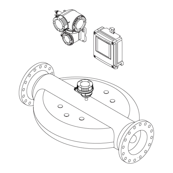
- Page 14 Product description Proline Promass X 500 FOUNDATION Fieldbus Product description The measuring system consists of a transmitter and a sensor. The transmitter and sensor are mounted in physically separate locations. They are interconnected by one connecting cable(s). Product design Two versions of the transmitter are available.
- Page 15 Proline Promass X 500 FOUNDATION Fieldbus Product description 3.1.2 Proline 500 Signal transmission: analog Order code for "Integrated ISEM electronics", option B "Transmitter" For use in applications required to meet special requirements due to ambient or operating conditions. As the electronics are located in the transmitter, the device is ideal in the event of: •...
- Page 16 A0028673 and documents present? • If one of the conditions is not satisfied, contact your Endress+Hauser Sales Center. • Depending on the device version, the CD-ROM might not be part of the delivery! The Technical Documentation is available via the Internet or via the Endress+Hauser Operations App, see the "Product identification"...
- Page 17 "Supplementary device-dependent documentation" → 8 • The W@M Device Viewer: Enter the serial number from the nameplate (www.endress.com/deviceviewer) • The Endress+Hauser Operations App: Enter the serial number from the nameplate or scan the 2-D matrix code (QR code) on the nameplate. 4.2.1 Transmitter nameplate Proline 500 –...
- Page 18 Incoming acceptance and product identification Proline Promass X 500 FOUNDATION Fieldbus Proline 500 3 4 5 Order code: Ser. no.: Ext. ord. cd.: Date: A0029192 4 Example of a transmitter nameplate Manufacturing location Name of the transmitter Order code Serial number (ser.
- Page 19 Proline Promass X 500 FOUNDATION Fieldbus Incoming acceptance and product identification 4.2.2 Sensor nameplate Order code: Ser. no.: Ext. ord. cd.: Date: A0029199 5 Example of a sensor nameplate Name of the sensor Manufacturing location Order code Serial number (ser. no.) Extended order code (Ext.
- Page 20 Incoming acceptance and product identification Proline Promass X 500 FOUNDATION Fieldbus 4.2.3 Symbols on measuring device Symbol Meaning WARNING! This symbol alerts you to a dangerous situation. Failure to avoid this situation can result in serious or fatal injury. Reference to documentation Refers to the corresponding device documentation.
- Page 21 Proline Promass X 500 FOUNDATION Fieldbus Storage and transport Storage and transport Storage conditions Observe the following notes for storage: • Store in the original packaging to ensure protection from shock. • Do not remove protective covers or protective caps installed on process connections.
- Page 22 Installation Proline Promass X 500 FOUNDATION Fieldbus 5.2.2 Measuring devices with lifting lugs CAUTION Special transportation instructions for devices with lifting lugs ‣ Only use the lifting lugs fitted on the device or flanges to transport the device. ‣ The device must always be secured at two lifting lugs at least.
- Page 23 Proline Promass X 500 FOUNDATION Fieldbus Installation To prevent measuring errors arising from accumulation of gas bubbles in the measuring tube, avoid the following mounting locations in the pipe: • Highest point of a pipeline. • Directly upstream of a free pipe outlet in a down pipe.
- Page 24 Installation Proline Promass X 500 FOUNDATION Fieldbus Orientation Recommendation Horizontal orientation, transmitter at bottom → 7, 24 A0015590 Horizontal orientation, transmitter at → 7, 24 side A0015592 Applications with low process temperatures may decrease the ambient temperature. To maintain the minimum ambient temperature for the transmitter, this orientation is recommended.
- Page 25 Proline Promass X 500 FOUNDATION Fieldbus Installation Temperature tables For detailed information on the temperature tables, see the separate document entitled "Safety Instructions" (XA) for the device. System pressure It is important that cavitation does not occur, or that gases entrained in the liquids do not outgas.
- Page 26 Installation Proline Promass X 500 FOUNDATION Fieldbus A0028853 Maximum insulation thickness Minimum distance to insulation The minimum distance a between the sensor connection housing and the insulation is 10 mm (0.39 in). This is to ensure that the sensor connection housing remains completely exposed.
- Page 27 Proline Promass X 500 FOUNDATION Fieldbus Installation Heating options If a fluid requires that no heat loss should occur at the sensor, users can avail of the following heating options: • Electrical heating, e.g. with electric band heaters • Via pipes carrying hot water or steam •...
- Page 28 Installation Proline Promass X 500 FOUNDATION Fieldbus RUPTURE DISK A0029944 Rupture disk label Rupture disk with 1/2" NPT internal thread with 1" width across flat Transport protection Zero point adjustment All measuring devices are calibrated in accordance with state-of-the-art technology.
- Page 29 Proline Promass X 500 FOUNDATION Fieldbus Installation 280 (11.0) 255 (10.0) 146 (5.75) 134 (5.3) 12 (0.47) 30 (1.18) A0029553 10 Weather protection cover for Proline 500 Cover locking: Proline 500 NOTICE Order code "Transmitter housing", option L "Cast, stainless": The covers of the transmitter housing are provided with a borehole to lock the cover.
- Page 30 Installation Proline Promass X 500 FOUNDATION Fieldbus For wall mounting: Drill with drill bit ⌀ 6.0 mm For sensor For flanges and other process connections: Corresponding mounting tools 6.2.2 Preparing the measuring device 1. Remove all remaining transport packaging. 2. Remove any protective covers or protective caps present from the sensor.
- Page 31 Proline Promass X 500 FOUNDATION Fieldbus Installation Post mounting WARNING Excessive tightening torque applied to the fixing screws! Risk of damaging the plastic transmitter. ‣ Tighten the fixing screws as per the tightening torque: 2 Nm (1.5 lbf ft) ø...
- Page 32 Installation Proline Promass X 500 FOUNDATION Fieldbus 2. Insert wall plugs into the drilled holes. 3. Screw in the securing screws slightly at first. 4. Fit the transmitter housing over the securing screws and mount in place. 5. Tighten the securing screws.
- Page 33 Proline Promass X 500 FOUNDATION Fieldbus Installation Post mounting WARNING Order code for "Transmitter housing", option L "Cast, stainless": cast transmitters are very heavy. They are unstable if they are not mounted on a secure, fixed post. ‣ Only mount the transmitter on a secure, fixed post on a stable surface.
- Page 34 Installation Proline Promass X 500 FOUNDATION Fieldbus 6.2.7 Turning the display module: Proline 500 The display module can be turned to optimize display readability and operability. – – – 3 mm A0030035 1. Loosen the securing clamp of the connection compartment cover.
- Page 35 Proline Promass X 500 FOUNDATION Fieldbus Electrical connection Electrical connection NOTICE The measuring device does not have an internal circuit breaker. ‣ For this reason, assign the measuring device a switch or power-circuit breaker so that the power supply line can be easily disconnected from the mains.
- Page 36 Electrical connection Proline Promass X 500 FOUNDATION Fieldbus Relay output Standard installation cable is sufficient. Current input 0/4 to 20 mA Standard installation cable is sufficient. Status input Standard installation cable is sufficient. Cable diameter • Cable glands supplied: M20 × 1.5 with cable ⌀ 6 to 12 mm (0.24 to 0.47 in) •...
- Page 37 Proline Promass X 500 FOUNDATION Fieldbus Electrical connection Standard cable 4, 6, 8 cores (2, 3, 4 pairs); pair-stranded with common shield Shielding Tin-plated copper-braid, optical cover ≥ 85 % Capacitance C Maximum 760 nF IIC, maximum 4.2 µF IIB Inductance L Maximum 26 µH IIC, maximum 104 µH IIB...
- Page 38 Electrical connection Proline Promass X 500 FOUNDATION Fieldbus Operating temperature When mounted in a fixed position: –50 to +105 °C (–58 to +221 °F); when cable can move freely: –25 to +105 °C (–13 to +221 °F) Available cable length Fixed: 20 m (65 ft);...
- Page 39 Proline Promass X 500 FOUNDATION Fieldbus Electrical connection Order code for "Input; output 1", option SA "FOUNDATION Fieldbus" Order code for Cable entry Cable entry "Electrical connection" M, 3, 4, 5 7/8" plug – 7.1.5 Pin assignment of device plug...
- Page 40 Electrical connection Proline Promass X 500 FOUNDATION Fieldbus Connecting the measuring device NOTICE Limitation of electrical safety due to incorrect connection! ‣ Have electrical connection work carried out by correspondingly trained specialists only. ‣ Observe applicable federal/national installation codes and regulations.
- Page 41 Proline Promass X 500 FOUNDATION Fieldbus Electrical connection Connection via connectors with order code for "Sensor Available for sensor connection housing" Option C "Ultra-compact hygienic, stainless" • Promass A, E, F, H, I, O, P, Q, S • CubemassC Connecting the connecting cable to the transmitter The cable is connected to the transmitter via terminals →...
- Page 42 Electrical connection Proline Promass X 500 FOUNDATION Fieldbus Connecting the sensor connection housing via terminals For the device version with the order code for "Sensor connection housing": Option L "Cast, stainless" 10 (0.4) 3 mm TX 20 TX 20 22 mm...
- Page 43 Proline Promass X 500 FOUNDATION Fieldbus Electrical connection Connecting the connecting cable to the transmitter TX 20 TX 20 10 (0.4) 22 mm 24 mm A0029597 1. Loosen the 4 fixing screws on the housing cover. 2. Open the housing cover.
- Page 44 Electrical connection Proline Promass X 500 FOUNDATION Fieldbus 7.2.2 Connecting the signal cable and the supply voltage cable A0028200 Cable entry for supply voltage Cable entry for cable or connection of device plug for signal transmission Cable entry for cable or connection of device plug for signal transmission...
- Page 45 Proline Promass X 500 FOUNDATION Fieldbus Electrical connection WARNING Housing degree of protection may be voided due to insufficient sealing of the housing. ‣ Screw in the screw without using any lubricant. WARNING Excessive tightening torque applied to the fixing screws! Risk of damaging the plastic transmitter.
- Page 46 Electrical connection Proline Promass X 500 FOUNDATION Fieldbus Connecting the measuring device NOTICE Limitation of electrical safety due to incorrect connection! ‣ Have electrical connection work carried out by correspondingly trained specialists only. ‣ Observe applicable federal/national installation codes and regulations.
- Page 47 Proline Promass X 500 FOUNDATION Fieldbus Electrical connection Connecting the sensor connection housing via terminals For the device version with the order code for "Housing": Option L "Cast, stainless" 10 (0.4) 3 mm 22 mm 24 mm A0029612 1. Loosen the securing clamp of the housing cover.
- Page 48 Electrical connection Proline Promass X 500 FOUNDATION Fieldbus Connecting the connecting cable to the transmitter 10 (0.4) 3 mm 22 mm 24 mm A0029592 1. Loosen the securing clamp of the connection compartment cover. 2. Unscrew the connection compartment cover.
- Page 49 Proline Promass X 500 FOUNDATION Fieldbus Electrical connection 7.3.2 Connecting the signal cable and the supply voltage cable A0026781 Cable entry for supply voltage Cable entry for signal transmission, input/output 1 and 2 Cable entry for input/output signal transmission; Optional: connection of external WLAN antenna or service plug –...
- Page 50 Electrical connection Proline Promass X 500 FOUNDATION Fieldbus 10 (0.4) mm (in) – A0029815 7. Push the cable through the cable entry . To ensure tight sealing, do not remove the sealing ring from the cable entry. 8. Strip the cable and cable ends. In the case of stranded cables, also fit ferrules.
- Page 51 Proline Promass X 500 FOUNDATION Fieldbus Electrical connection Removing a cable 3 (0.12) A0029598 16 Engineering unit mm (in) 1. To remove a cable from the terminal, use a flat-blade screwdriver to push the slot between the two terminal holes 2.
- Page 52 Electrical connection Proline Promass X 500 FOUNDATION Fieldbus Special connection instructions 7.5.1 Connection examples FOUNDATION Fieldbus A0028768 17 Connection example for FOUNDATION Fieldbus Control system (e.g. PLC) Power Conditioner (FOUNDATION Fieldbus) Cable shield: the cable shield must be grounded at both ends to comply with EMC requirements; observe cable...
- Page 53 Proline Promass X 500 FOUNDATION Fieldbus Electrical connection 4...20 mA A0028759 19 Connection example for 4-20 mA current output (passive) Automation system with current input (e.g. PLC) Active barrier for power supply (e.g. RN221N) Analog display unit: observe maximum load...
- Page 54 Electrical connection Proline Promass X 500 FOUNDATION Fieldbus Relay output A0028760 22 Connection example for relay output (passive) Automation system with relay input (e.g. PLC) Power supply Transmitter: Observe input values → 201 Current input A0028915 23...
- Page 55 Proline Promass X 500 FOUNDATION Fieldbus Electrical connection To guarantee IP66/67 degree of protection, Type 4X enclosure, carry out the following steps after the electrical connection: 1. Check that the housing seals are clean and fitted correctly. 2. Dry, clean or replace the seals if necessary.
- Page 56 Operation options Proline Promass X 500 FOUNDATION Fieldbus Operation options Overview of operation options A0029295 Local operation via display module Computer with Web browser (e.g. Internet Explorer) or with operating tool (e.g. FieldCare, DeviceCare, AMS Device Manager, SIMATIC PDM) Field Xpert SFX350 or SFX370...
- Page 57 Proline Promass X 500 FOUNDATION Fieldbus Operation options Structure and function of the operating menu 8.2.1 Structure of the operating menu For an overview of the operating menu for experts: "Description of Device Parameters" document supplied with the device→ 225...
- Page 58 Operation options Proline Promass X 500 FOUNDATION Fieldbus 8.2.2 Operating philosophy The individual parts of the operating menu are assigned to certain user roles (operator, maintenance etc.). Each user role contains typical tasks within the device lifecycle. For custody transfer, once the device has been put into circulation or sealed, its operation is restricted.
- Page 59 Proline Promass X 500 FOUNDATION Fieldbus Operation options Menu/parameter User role and tasks Content/meaning Expert function-oriented Tasks that require detailed Contains all the parameters of the device and makes it possible to access knowledge of the function of the these parameters directly using an access code. The structure of this menu is...
- Page 60 Operation options Proline Promass X 500 FOUNDATION Fieldbus Status area The following symbols appear in the status area of the operational display at the top right: • Status signals→ 154 – F: Failure – C: Function check – S: Out of specification –...
- Page 61 Proline Promass X 500 FOUNDATION Fieldbus Operation options 8.3.2 Navigation view In the submenu In the wizard /../Operation 0091-1 /../Select medium Access stat.disp Select medium Operator Liquid Locking status Display A0013993-EN A0013995-EN Navigation view Navigation path to current position Status area Display area for navigation Operating elements →...
- Page 62 Operation options Proline Promass X 500 FOUNDATION Fieldbus Display area Menus Symbol Meaning Operation Appears: • In the menu next to the "Operation" selection • At the left in the navigation path in the Operation menu Setup Appears: • In the menu next to the "Setup" selection •...
- Page 63 Proline Promass X 500 FOUNDATION Fieldbus Operation options 8.3.3 Editing view Numeric editor Text editor User ABC_ DEFG HIJK LMNO PQRS TUVW A0013999 A0013941 Editing view Display area of the entered values Input mask Operating elements → 64 Input mask...
- Page 64 Operation options Proline Promass X 500 FOUNDATION Fieldbus Selection of letters from a to z. abc _ … Selection of special characters. "'^ _ … ~& Confirms selection. Switches to the selection of the correction tools. Exits the input without applying the changes.
- Page 65 Proline Promass X 500 FOUNDATION Fieldbus Operation options Meaning Enter key For operational display • Pressing the key briefly opens the operating menu. • Pressing the key for 2 s opens the context menu. In a menu, submenu • Pressing the key briefly: –...
- Page 66 Operation options Proline Promass X 500 FOUNDATION Fieldbus 2. Press + simultaneously. The context menu is closed and the operational display appears. Calling up the menu via the context menu 1. Open the context menu. 2. Press to navigate to the desired menu.
- Page 67 Proline Promass X 500 FOUNDATION Fieldbus Operation options 8.3.6 Navigating and selecting from list Different operating elements are used to navigate through the operating menu. The navigation path is displayed on the left in the header. Icons are displayed in front of the individual menus.
- Page 68 Operation options Proline Promass X 500 FOUNDATION Fieldbus The direct access code consists of a 4-digit number and the channel number, which identifies the channel of a process variable: e.g. 0914-1. In the navigation view, this appears on the right-hand side in the header of the selected parameter.
- Page 69 Proline Promass X 500 FOUNDATION Fieldbus Operation options 8.3.9 Changing the parameters For a description of the editing display - consisting of text editor and numeric editor - with symbols → 63, for a description of the operating elements → 64 Example: Changing the tag name in the "Tag description"...
- Page 70 Operation options Proline Promass X 500 FOUNDATION Fieldbus Ent. access code Invalid or out of range input value Min:0 Max:9999 A0014049-EN 8.3.10 User roles and related access authorization The two user roles "Operator" and "Maintenance" have different write access to the parameters if the customer defines a user-specific access code.
- Page 71 Proline Promass X 500 FOUNDATION Fieldbus Operation options Local operation with touch control The keypad lock is switched on and off via the context menu. Switching on the keypad lock The keypad lock is switched on automatically: • Each time the device is restarted.
- Page 72 Operation options Proline Promass X 500 FOUNDATION Fieldbus Computer software Software Interface CDI-RJ45 WLAN Recommended operating • Microsoft Windows 7 or higher. systems • Mobile operating systems: – iOS – Android Microsoft Windows XP is supported. Web browsers supported •...
- Page 73 Proline Promass X 500 FOUNDATION Fieldbus Operation options 8.4.3 Establishing a connection Via service interface (CDI-RJ45) Preparing the measuring device Proline 500 – digital 1. Loosen the 4 fixing screws on the housing cover. 2. Open the housing cover. 3. The location of the connection socket depends on the measuring device and the...
- Page 74 Operation options Proline Promass X 500 FOUNDATION Fieldbus NOTICE In principle, avoid simultaneous access to the measuring device via the service interface (CDI-RJ45) and the WLAN interface from the same mobile terminal. This could cause a network conflict. ‣ Only activate one service interface (CDI-RJ45 service interface or WLAN interface).
- Page 75 Proline Promass X 500 FOUNDATION Fieldbus Operation options 2. Enter the IP address of the Web server in the address line of the Web browser: 192.168.1.212 The login page appears. 2 3 4 A0029417 Picture of device Device name...
- Page 76 Operation options Proline Promass X 500 FOUNDATION Fieldbus 8.4.5 User interface A0029418 Function row Operating language on the local display Navigation area Header The following information appears in the header: • Device tag • Device status with status signal → 157 •...
- Page 77 Proline Promass X 500 FOUNDATION Fieldbus Operation options Working area Depending on the selected function and the related submenus, various actions can be performed in this area: • Configuring parameters • Reading measured values • Calling up help text • Starting an upload/download 8.4.6...
- Page 78 Operation options Proline Promass X 500 FOUNDATION Fieldbus 8.5.1 Connecting the operating tool Via FOUNDATION Fieldbus network This communication interface is available in device versions with FOUNDATION Fieldbus. A0028837 27 Options for remote operation via FOUNDATION Fieldbus network Automation system...
- Page 79 Proline Promass X 500 FOUNDATION Fieldbus Operation options Proline 500 transmitter A0027563 29 Connection via service interface (CDI-RJ45) Computer with Web browser (e.g. Microsoft Internet Explorer, Microsoft Edge) for accessing the integrated device Web server or with "FieldCare", "DeviceCare" operating tool with COM DTM "CDI Communication TCP/IP"...
- Page 80 Operation options Proline Promass X 500 FOUNDATION Fieldbus Configurable channels 1 to 11 Function Access point with DHCP Range with integrated Max. 10 m (32 ft) antenna Range with external Max. 50 m (164 ft) antenna Configuring the Internet protocol of the mobile terminal NOTICE If the WLAN connection is lost during the configuration, settings made may be lost.
- Page 81 FieldCare Function scope FDT-based plant asset management tool from Endress+Hauser. It can configure all smart field devices in a system and helps you manage them. By using the status information, it is also a simple but effective way of checking their status and condition.
- Page 82 DeviceCare Function scope Tool to connect and configure Endress+Hauser field devices. The fastest way to configure Endress+Hauser field devices is with the dedicated "DeviceCare" tool. Together with the device type managers (DTMs) it presents a convenient, comprehensive solution. For details, see Innovation Brochure IN01047S Source for device description files See information →...
- Page 83 Proline Promass X 500 FOUNDATION Fieldbus Operation options Source for device description files See data → 84 8.5.6 Field Communicator 475 Function scope Industrial handheld terminal from Emerson Process Management for remote configuration and measured value display via FOUNDATION Fieldbus H1 protocol.
- Page 84 System integration Proline Promass X 500 FOUNDATION Fieldbus System integration Overview of device description files 9.1.1 Current version data for the device Firmware version 01.00.zz • On the title page of the Operating instructions • On the transmitter nameplate • Firmware version Diagnostics →...
- Page 85 Proline Promass X 500 FOUNDATION Fieldbus System integration Display text (xxxx... = serial number) Base index Description RESOURCE_ xxxxxxxxxxx Resource block SETUP_ xxxxxxxxxxx "Setup" Transducer block TRDDISP_ xxxxxxxxxxx "Display" Transducer block TRDHROM_ xxxxxxxxxxx 1000 "HistoROM" Transducer block TRDDIAG_ xxxxxxxxxxx 1200 "Diagnostic"...
- Page 86 System integration Proline Promass X 500 FOUNDATION Fieldbus CHANNEL Measured variable Frequency fluctuation Carrier pipe temperature Carrier mass flow Target mass flow Oscillation damping Electronic temperature Tube damping fluctuation Exciter current HBSI Current input 1 Visible depending on the order options or device settings...
- Page 87 Proline Promass X 500 FOUNDATION Fieldbus System integration CHANNEL Device function State Empty pipe detection 0 = off, 1 = active Verification status Overall result of the verification Verification: • 16 = Failed • 32 = Passed • 64 = Not performed...
- Page 88 System integration Proline Promass X 500 FOUNDATION Fieldbus Value Device function State Value 7 Zero point adjustment 0 = off, 1 = on Value 8 Not assigned – Only available with the Heartbeat Verification application package 9.2.3 Execution times Function block...
- Page 89 Proline Promass X 500 FOUNDATION Fieldbus System integration 9.2.4 Methods Method Block Navigation Description Set to "AUTO" mode Resource Block Via menu: This method sets the Resource Block and all the Expert → Communication → Resource block Transducer Blocks to the AUTO (Automatic) →...
- Page 90 Commissioning Proline Promass X 500 FOUNDATION Fieldbus Commissioning 10.1 Function check Before commissioning the measuring device: ‣ Make sure that the post-installation and post-connection checks have been performed. • "Post-installation check" checklist → 34 • "Post-connection check" checklist → 55 10.2...
- Page 91 Proline Promass X 500 FOUNDATION Fieldbus Commissioning 10.5 Configuring the measuring device • The Setup menuwith its guided wizards contains all the parameters needed for standard operation. • Navigation to the Setup menu X X X X X X X 20.50...
- Page 92 Commissioning Proline Promass X 500 FOUNDATION Fieldbus ‣ Low flow cut off → 117 ‣ Partially filled pipe detection → 118 ‣ Advanced setup → 119 10.5.1 Defining the tag name To enable fast identification of the measuring point within the system, you can enter a unique designation using the Device tag parameter and thus change the factory setting.
- Page 93 Proline Promass X 500 FOUNDATION Fieldbus Commissioning Volume unit → 93 Corrected volume flow unit → 93 Corrected volume unit → 93 Density unit → 93 Reference density unit → 93 → 94 Temperature unit Pressure unit →...
- Page 94 Commissioning Proline Promass X 500 FOUNDATION Fieldbus Parameter Description Selection Factory setting Temperature unit Select temperature unit. Unit choose list Country-specific: • °C Result • °F The selected unit applies for: • Electronic temperature parameter (6053) • Maximum value parameter (6051) •...
- Page 95 Proline Promass X 500 FOUNDATION Fieldbus Commissioning 10.5.3 Selecting and setting the medium The Select medium wizard submenu contains parameters that must be configured in order to select and set the medium. Navigation "Setup" menu → Select medium ‣ Medium selection Select medium →...
- Page 96 Commissioning Proline Promass X 500 FOUNDATION Fieldbus Parameter overview with brief description Parameter Prerequisite Description Selection / User Factory setting entry / User interface Select medium – Select medium type. • Liquid Liquid • Gas Select gas type The Gas option is selected in Select measured gas type.
- Page 97 Proline Promass X 500 FOUNDATION Fieldbus Commissioning 10.5.4 Configuring the analog inputs The Analog inputs submenu guides the user systematically to the individual Analog input 1 to n submenu. From here you get to the parameters of the individual analog input.
- Page 98 Commissioning Proline Promass X 500 FOUNDATION Fieldbus Navigation "Setup" menu → I/O configuration ‣ I/O configuration → 98 I/O module 1 to n terminal numbers → 98 I/O module 1 to n information I/O module 1 to n type →...
- Page 99 Proline Promass X 500 FOUNDATION Fieldbus Commissioning Signal mode → 99 0/4 mA value → 99 20 mA value → 99 Current span → 99 Failure mode → 99 → 99 Failure value Parameter overview with brief description...
- Page 100 Commissioning Proline Promass X 500 FOUNDATION Fieldbus Terminal number → 100 Active level → 100 Terminal number → 100 Response time status input → 100 Terminal number → 100 Parameter overview with brief description Parameter Description User interface / Selection / ...
- Page 101 Proline Promass X 500 FOUNDATION Fieldbus Commissioning Failure mode → 102 Failure current → 102 Parameter overview with brief description Parameter Prerequisite Description Selection / User Factory setting interface / User entry Assign current output – Select process variable for • Off Mass flow current output.
- Page 102 Commissioning Proline Promass X 500 FOUNDATION Fieldbus Parameter Prerequisite Description Selection / User Factory setting interface / User entry Fixed current In the Current span parameter Defines the fixed output 0 to 22.5 mA 22.5 mA (→ 101), the Fixed current current. option is selected.
- Page 103 Proline Promass X 500 FOUNDATION Fieldbus Commissioning 10.5.9 Configuring the pulse/frequency/switch output The Pulse/frequency/switch output wizard guides you systematically through all the parameters that can be set for configuring the selected output type. Navigation "Setup" menu → Advanced setup → Pulse/frequency/switch output ‣...
- Page 104 Commissioning Proline Promass X 500 FOUNDATION Fieldbus Parameter overview with brief description Parameter Prerequisite Description Selection / User Factory setting interface / User entry Operating mode – Define the output as a pulse, • Pulse Pulse frequency or switch output. • Frequency • Switch Terminal number –...
- Page 105 Proline Promass X 500 FOUNDATION Fieldbus Commissioning Configuring the frequency output Navigation "Setup" menu → Pulse/frequency/switch output ‣ Pulse/frequency/switch output 1 to n Operating mode → 105 Terminal number → 105 Signal mode → 105 → 106...
- Page 106 Commissioning Proline Promass X 500 FOUNDATION Fieldbus Parameter Prerequisite Description Selection / User Factory setting interface / User entry Assign frequency output In the Operating mode Select process variable for • Off parameter (→ 103), the frequency output. • Mass flow Frequency option is selected.
- Page 107 Proline Promass X 500 FOUNDATION Fieldbus Commissioning Parameter Prerequisite Description Selection / User Factory setting interface / User entry Maximum frequency value In the Operating mode Enter maximum frequency. 0.0 to 10 000.0 Hz 10 000.0 Hz parameter the Frequency option is selected and in the Assign frequency output parameter (→...
- Page 108 Commissioning Proline Promass X 500 FOUNDATION Fieldbus Parameter Prerequisite Description Selection / User Factory setting interface / User entry Measuring value at maximum In the Operating mode Enter measured value for Signed floating-point Depends on country frequency parameter the Frequency maximum frequency. number and nominal...
- Page 109 Proline Promass X 500 FOUNDATION Fieldbus Commissioning Parameter Prerequisite Description Selection / User Factory setting interface / User entry Failure frequency In the Operating mode Enter frequency output value 0.0 to 12 500.0 Hz 0.0 Hz parameter the Frequency in alarm condition. option is selected and in the Assign frequency output parameter (→...
- Page 110 Commissioning Proline Promass X 500 FOUNDATION Fieldbus Configuring the switch output Navigation "Setup" menu → Pulse/frequency/switch output ‣ Pulse/frequency/switch output 1 to n Operating mode → 110 Terminal number → 110 Signal mode → 110 → 111...
- Page 111 Proline Promass X 500 FOUNDATION Fieldbus Commissioning Parameter Prerequisite Description Selection / User Factory setting interface / User entry Switch output function In the Operating mode Select function for switch • Off parameter the Switch option is output. • On selected. • Diagnostic behavior •...
- Page 112 Commissioning Proline Promass X 500 FOUNDATION Fieldbus Parameter Prerequisite Description Selection / User Factory setting interface / User entry Switch-off delay • The Switch option is Define delay for the switch-off 0.0 to 100.0 s 0.0 s selected in the Operating of status output.
- Page 113 Proline Promass X 500 FOUNDATION Fieldbus Commissioning Parameter overview with brief description Parameter Prerequisite Description Selection / User Factory setting interface / User entry Relay output function – Select the function for the • Closed Closed relay output. • Open • Diagnostic behavior • Limit •...
- Page 114 Commissioning Proline Promass X 500 FOUNDATION Fieldbus 10.5.11 Configuring the local display The Display wizard guides you systematically through all the parameters that can configured for configuring the local display. Navigation "Setup" menu → Display ‣ Display → 115 Format display →...
- Page 115 Proline Promass X 500 FOUNDATION Fieldbus Commissioning Parameter overview with brief description Parameter Prerequisite Description Selection / User Factory setting entry Format display A local display is provided. Select how measured values • 1 value, max. size 1 value, max. size are shown on the display.
- Page 116 Commissioning Proline Promass X 500 FOUNDATION Fieldbus Parameter Prerequisite Description Selection / User Factory setting entry 100% bargraph value 3 A selection was made in the Enter 100% value for bar Signed floating-point Value 3 display parameter. graph display. number Value 4 display A local display is provided.
- Page 117 Proline Promass X 500 FOUNDATION Fieldbus Commissioning 10.5.12 Configuring the low flow cut off The Low flow cut off wizard systematically guides the user through all the parameters that must be set to configure low flow cut off. Navigation "Setup" menu → Low flow cut off ‣...
- Page 118 Commissioning Proline Promass X 500 FOUNDATION Fieldbus 10.5.13 Configuring the partial filled pipe detection The Partial filled pipe detection wizard guides you systematically through all parameters that have to be set for configuring the monitoring of the pipe filling. Navigation "Setup"...
- Page 119 Proline Promass X 500 FOUNDATION Fieldbus Commissioning 10.6 Advanced settings The Advanced setup submenu together with its submenus contains parameters for specific settings. Navigation to the "Advanced setup" submenu X X X X X X X 20.50 0104-1 Main menu...
- Page 120 Commissioning Proline Promass X 500 FOUNDATION Fieldbus ‣ WLAN settings → 127 ‣ Concentration ‣ Heartbeat setup ‣ Configuration backup → 128 ‣ Administration → 129 10.6.1 Using the parameter to enter the access code Navigation "Setup" menu → Advanced setup...
- Page 121 Proline Promass X 500 FOUNDATION Fieldbus Commissioning Parameter overview with brief description Parameter Prerequisite Description Selection / User Factory setting interface / User entry Corrected volume flow calculation – Select reference density for • Fixed reference Calculated reference calculating the corrected density density volume flow.
- Page 122 Commissioning Proline Promass X 500 FOUNDATION Fieldbus Parameter overview with brief description Parameter Description Selection Factory setting Installation direction Set sign of flow direction to match the • Flow in arrow direction Flow in arrow direction direction of the arrow on the sensor.
- Page 123 Proline Promass X 500 FOUNDATION Fieldbus Commissioning Parameter overview with brief description Parameter Prerequisite Description Selection Factory setting Assign process variable – Select process variable for • Off Mass flow totalizer. • Volume flow • Mass flow • Corrected volume flow •...
- Page 124 Commissioning Proline Promass X 500 FOUNDATION Fieldbus 10.6.5 Carrying out additional display configurations In the Display submenu you can set all the parameters associated with the configuration of the local display. Navigation "Setup" menu → Advanced setup → Display ‣...
- Page 125 Proline Promass X 500 FOUNDATION Fieldbus Commissioning Parameter overview with brief description Parameter Prerequisite Description Selection / User Factory setting entry Format display A local display is provided. Select how measured values • 1 value, max. size 1 value, max. size are shown on the display.
- Page 126 Commissioning Proline Promass X 500 FOUNDATION Fieldbus Parameter Prerequisite Description Selection / User Factory setting entry 0% bargraph value 3 A selection was made in the Enter 0% value for bar graph Signed floating-point Country-specific: Value 3 display parameter. display. number • 0 kg/h •...
- Page 127 Proline Promass X 500 FOUNDATION Fieldbus Commissioning Parameter Prerequisite Description Selection / User Factory setting entry Separator A local display is provided. Select decimal separator for • . (point) . (point) displaying numerical values. • , (comma) Backlight One of the following Switch the local display •...
- Page 128 Commissioning Proline Promass X 500 FOUNDATION Fieldbus Parameter Prerequisite Description User entry / Factory setting Selection Assign SSID name – Select which name will be used • Device tag User-defined for SSID: device tag or user- • User-defined defined name. SSID name...
- Page 129 Proline Promass X 500 FOUNDATION Fieldbus Commissioning Parameter Description User interface / Selection Factory setting Backup state Shows the current status of data saving or • None None restoring. • Backup in progress • Restoring in progress • Delete in progress • Compare in progress •...
- Page 130 Commissioning Proline Promass X 500 FOUNDATION Fieldbus Using the parameter to define the access code Navigation "Setup" menu → Advanced setup → Administration → Define access code ‣ Define access code Define access code → 130 Confirm access code →...
- Page 131 Proline Promass X 500 FOUNDATION Fieldbus Commissioning Parameter overview with brief description Parameter Description Selection Factory setting Device reset Reset the device configuration - either • Cancel Cancel entirely or in part - to a defined state. • To delivery settings •...
- Page 132 Commissioning Proline Promass X 500 FOUNDATION Fieldbus Device alarm simulation → 133 Diagnostic event category → 133 Diagnostic event simulation → 133 Parameter overview with brief description Parameter Prerequisite Description Selection / User Factory setting entry / User interface Assign simulation process variable –...
- Page 133 Proline Promass X 500 FOUNDATION Fieldbus Commissioning Parameter Prerequisite Description Selection / User Factory setting entry / User interface Pulse output simulation In the Operating mode Set and switch off the pulse • Off parameter, the Pulse option is output simulation. • Fixed value selected.
- Page 134 Commissioning Proline Promass X 500 FOUNDATION Fieldbus 10.8 Protecting settings from unauthorized access The following write protection options exist in order to protect the configuration of the measuring device from unintentional modification: • Protect access to parameters via access code → 134 •...
- Page 135 Via Web browser, FieldCare, DeviceCare (via CDI-RJ45 service interface), fieldbus For a reset code, contact your Endress+Hauser service organization. 1. Navigate to the Reset access code parameter (→ 130). 2. Enter the reset code.
- Page 136 Commissioning Proline Promass X 500 FOUNDATION Fieldbus A0029675 1. Open the housing cover. 2. Remove the display module. 3. Fold open the terminal cover. 4. Setting the write protection (WP) switch on the main electronics module to the ON position enables hardware write protection.
- Page 137 Proline Promass X 500 FOUNDATION Fieldbus Commissioning Proline 500 A0029630 Setting the write protection (WP) switch on the main electronics module to the ON position enables hardware write protection. In the Locking status parameter the Hardware locked option is displayed →...
- Page 138 Operation Proline Promass X 500 FOUNDATION Fieldbus Operation 11.1 Reading the device locking status Device active write protection: Locking status parameter Operation → Locking status Function scope of the "Locking status" parameter Options Description None The access status displayed in the Access status parameter applies → 70. Only appears on local display.
- Page 139 Proline Promass X 500 FOUNDATION Fieldbus Operation 11.4.1 "Measured variables" submenu The Measured variables submenu contains all the parameters needed to display the current measured values for each process variable. Navigation "Diagnostics" menu → Measured values → Measured variables ‣...
- Page 140 Operation Proline Promass X 500 FOUNDATION Fieldbus Parameter Prerequisite Description User interface Reference density – Displays the reference density currently Signed floating-point calculated. number Dependency The unit is taken from the Reference density unit parameter (→ 93). Temperature –...
- Page 141 Proline Promass X 500 FOUNDATION Fieldbus Operation Parameter overview with brief description Parameter Prerequisite Description User interface Totalizer value 1 to n A process variable is selected in the Displays the current totalizer counter Signed floating-point Assign process variable parameter value.
- Page 142 Operation Proline Promass X 500 FOUNDATION Fieldbus Navigation "Diagnostics" menu → Measured values → Input values → Status input 1 to n ‣ Status input 1 to n → 142 Value status input Parameter overview with brief description Parameter...
- Page 143 Proline Promass X 500 FOUNDATION Fieldbus Operation Parameter overview with brief description Parameter Description User interface Output current 1 Displays the current value currently calculated for the current 3.59 to 22.5 mA output. Measured current Displays the current value currently measured for the current 0 to 30 mA output.
- Page 144 Operation Proline Promass X 500 FOUNDATION Fieldbus Parameter overview with brief description Parameter Description User interface Switch status Shows the current relay switch status. • Open • Closed Switch cycles Shows number of all performed switch cycles. Positive integer Max. switch cycles number Shows the maximal number of guaranteed switch cycles.
- Page 145 Proline Promass X 500 FOUNDATION Fieldbus Operation Parameter overview with brief description Parameter Prerequisite Description Selection / User Factory setting entry Control Totalizer 1 to n One of the following options is Control totalizer value. • Totalize Totalize selected in the Assign process •...
- Page 146 Operation Proline Promass X 500 FOUNDATION Fieldbus Function range • A total of 1000 measured values can be stored • 4 logging channels • Adjustable logging interval for data logging • Display of the measured value trend for each logging channel in the form of a chart / ../XXXXXXXX...
- Page 147 Proline Promass X 500 FOUNDATION Fieldbus Operation Parameter overview with brief description Parameter Prerequisite Description Selection / User Factory setting entry / User interface Assign channel 1 to n The Extended HistoROM Assign process variable to • Off application package is logging channel. • Mass flow available.
- Page 148 Diagnostics and troubleshooting Proline Promass X 500 FOUNDATION Fieldbus Diagnostics and troubleshooting 12.1 General troubleshooting For local display Error Possible causes Solution Local display dark and no output Supply voltage does not match the Apply the correct supply voltage .
- Page 149 Proline Promass X 500 FOUNDATION Fieldbus Diagnostics and troubleshooting For output signals Error Possible causes Solution Signal output outside the valid Main electronics module is Order spare part → 192. range defective. Device shows correct value on local Configuration error...
- Page 150 Diagnostics and troubleshooting Proline Promass X 500 FOUNDATION Fieldbus Error Possible causes Solution Connection lost 1. Check cable connection and power supply. 2. Refresh the Web browser and restart if necessary. Content of Web browser Not using optimum version of Web 1.
- Page 151 Proline Promass X 500 FOUNDATION Fieldbus Diagnostics and troubleshooting A0029689 Supply voltage Device status Not used Communication Service interface (CDI) active 1. Open the housing cover. 2. Remove the display module. 3. Fold open the terminal cover. Color Meaning Supply voltage...
- Page 152 Diagnostics and troubleshooting Proline Promass X 500 FOUNDATION Fieldbus 1 2 3 4 5 A0029629 Supply voltage Device status Not used Communication Service interface (CDI) active Color Meaning Supply voltage Green Supply voltage is ok Supply voltage is off or too low...
- Page 153 Proline Promass X 500 FOUNDATION Fieldbus Diagnostics and troubleshooting Color Meaning Supply voltage Green Supply voltage is ok Supply voltage is off or too low Endress+Hauser...
- Page 154 Diagnostics and troubleshooting Proline Promass X 500 FOUNDATION Fieldbus 12.3 Diagnostic information on local display 12.3.1 Diagnostic message Faults detected by the self-monitoring system of the measuring device are displayed as a diagnostic message in alternation with the operational display.
- Page 155 Proline Promass X 500 FOUNDATION Fieldbus Diagnostics and troubleshooting Diagnostic behavior Symbol Meaning Alarm • Measurement is interrupted. • Signal outputs and totalizers assume the defined alarm condition. • A diagnostic message is generated. Warning Measurement is resumed. The signal outputs and totalizers are not affected. A diagnostic message is generated.
- Page 156 Diagnostics and troubleshooting Proline Promass X 500 FOUNDATION Fieldbus 12.3.2 Calling up remedial measures X X X X X X X X X X X X X X 20.50 S801 Supply voltage Menu Diagnostic list Diagnostics 1 S801 Supply voltage...
- Page 157 Proline Promass X 500 FOUNDATION Fieldbus Diagnostics and troubleshooting A0031056 Status area with status signal Diagnostic information→ 155 Remedy information with Service ID In addition, diagnostic events which have occurred can be shown in the Diagnostics menu: • Via parameter •...
- Page 158 Diagnostics and troubleshooting Proline Promass X 500 FOUNDATION Fieldbus Xxxxxx/…/…/ Device name: Xxxxxxx Mass flow: kg/h 12.34 Device tag: Xxxxxxx Volume flow: 12.34 m /h ³ Status signal: Function check (C) Xxxxxx Diagnostics 1: C485 Simu... Remedy information: Deactivate... Failure (F)
- Page 159 Proline Promass X 500 FOUNDATION Fieldbus Diagnostics and troubleshooting The user is in the Diagnostics menu. 1. Call up the desired parameter. 2. On the right in the working area, mouse over the parameter. A tool tip with remedy information for the diagnostic event appears.
- Page 160 Diagnostics and troubleshooting Proline Promass X 500 FOUNDATION Fieldbus Symbol Meaning Out of specification The device is being operated: • Outside its technical specification limits (e.g. outside the process temperature range) • Outside of the configuration carried out by the user (e.g. maximum flow in parameter...
- Page 161 Proline Promass X 500 FOUNDATION Fieldbus Diagnostics and troubleshooting Weighting Status signal Allocation Diagnostic information range (factory setting) Configuration C400 to 700 Process C800 to 999 Weighting Status signal Allocation Diagnostic information range (factory setting) Out of specification (S) Sensor...
- Page 162 Diagnostics and troubleshooting Proline Promass X 500 FOUNDATION Fieldbus Weighting Allocation FAIL_ CHECK_ OFFSPEC_ MAINT_ Process Sensor Electronics Configuration Process Configurable range → 162 15 to Reserved (Fieldbus Foundation) Changing the status signal for a range of diagnostic information Example: The status signal for the diagnostic information for electronics with the "Highest"...
- Page 163 Proline Promass X 500 FOUNDATION Fieldbus Diagnostics and troubleshooting 6. In the FieldCare navigation window: Expert → Communication → Field diagnostics → Alarm broadcast enable 7. Select the desired diagnostic information from one of the fields Configurable Area Bits 1 to Configurable Area Bits 15.
- Page 164 Diagnostics and troubleshooting Proline Promass X 500 FOUNDATION Fieldbus 12.7.1 Diagnostic of sensor Diagnostic information Remedy instructions Influenced measured variables Short text 022 Temperature sensor defective 1. Check or replace sensor • Empty pipe detection electronic module (ISEM) • Low flow cut off Measured variable status 2.
- Page 165 Proline Promass X 500 FOUNDATION Fieldbus Diagnostics and troubleshooting Diagnostic information Remedy instructions Influenced measured variables Short text 063 Exciter current faulty 1. Check or replace sensor • Empty pipe detection electronic module (ISEM) • Low flow cut off Measured variable status 2.
- Page 166 Diagnostics and troubleshooting Proline Promass X 500 FOUNDATION Fieldbus Diagnostic information Remedy instructions Influenced measured variables Short text 144 Measuring error too high 1. Check or change sensor • Empty pipe detection 2. Check process conditions • Low flow cut off Measured variable status [from the factory] •...
- Page 167 Proline Promass X 500 FOUNDATION Fieldbus Diagnostics and troubleshooting Diagnostic information Remedy instructions Influenced measured variables Short text 252 Modules incompatible 1. Check electronic modules • Empty pipe detection 2. Change electronic modules • Low flow cut off Measured variable status •...
- Page 168 Diagnostics and troubleshooting Proline Promass X 500 FOUNDATION Fieldbus Diagnostic information Remedy instructions Influenced measured variables Short text 272 Main electronic failure 1. Restart device • Empty pipe detection 2. Contact service • Low flow cut off Measured variable status •...
- Page 169 Proline Promass X 500 FOUNDATION Fieldbus Diagnostics and troubleshooting Diagnostic information Remedy instructions Influenced measured variables Short text 276 I/O module 1 to n faulty 1. Restart device • Empty pipe detection 2. Change I/O module • Low flow cut off Measured variable status •...
- Page 170 Diagnostics and troubleshooting Proline Promass X 500 FOUNDATION Fieldbus Diagnostic information Remedy instructions Influenced measured variables Short text 332 Writing in embedded HistoROM failed Replace user interface board • Empty pipe detection Ex d/XP: replace transmitter • Low flow cut off Measured variable status •...
- Page 171 Proline Promass X 500 FOUNDATION Fieldbus Diagnostics and troubleshooting Diagnostic information Remedy instructions Influenced measured variables Short text 374 Sensor electronic (ISEM) faulty 1. Restart device • Empty pipe detection 2. Check if failure recurs • Low flow cut off Measured variable status [from the factory] 3.
- Page 172 Diagnostics and troubleshooting Proline Promass X 500 FOUNDATION Fieldbus Diagnostic information Remedy instructions Influenced measured variables Short text 387 Embedded HistoROM failed Contact service organization • Empty pipe detection • Low flow cut off Measured variable status • Switch output status •...
- Page 173 Proline Promass X 500 FOUNDATION Fieldbus Diagnostics and troubleshooting Diagnostic information Remedy instructions Influenced measured variables Short text 410 Data transfer 1. Check connection • Empty pipe detection 2. Retry data transfer • Low flow cut off Measured variable status •...
- Page 174 Diagnostics and troubleshooting Proline Promass X 500 FOUNDATION Fieldbus Diagnostic information Remedy instructions Influenced measured variables Short text 438 Dataset 1. Check data set file • Empty pipe detection 2. Check device configuration • Low flow cut off Measured variable status 3.
- Page 175 Proline Promass X 500 FOUNDATION Fieldbus Diagnostics and troubleshooting Diagnostic information Remedy instructions Influenced measured variables Short text 443 Pulse output 1 to n 1. Check process – 2. Check pulse output settings Measured variable status Quality Good Quality substatus...
- Page 176 Diagnostics and troubleshooting Proline Promass X 500 FOUNDATION Fieldbus Diagnostic information Remedy instructions Influenced measured variables Short text 463 Analog input 1 to n selection invalid 1. Check module/channel • Empty pipe detection configuration • Low flow cut off Measured variable status 2.
- Page 177 Proline Promass X 500 FOUNDATION Fieldbus Diagnostics and troubleshooting Diagnostic information Remedy instructions Influenced measured variables Short text 491 Current output 1 to n simulation Deactivate simulation – Measured variable status Quality Good Quality substatus Non specific Status signal [from the factory]...
- Page 178 Diagnostics and troubleshooting Proline Promass X 500 FOUNDATION Fieldbus Diagnostic information Remedy instructions Influenced measured variables Short text 495 Diagnostic event simulation Deactivate simulation – Measured variable status Quality Good Quality substatus Non specific Status signal [from the factory] Diagnostic behavior Warning Status signal can be changed.
- Page 179 Proline Promass X 500 FOUNDATION Fieldbus Diagnostics and troubleshooting Diagnostic information Remedy instructions Influenced measured variables Short text 537 Configuration 1. Check IP addresses in network – 2. Change IP address Measured variable status Quality Good Quality substatus Non specific...
- Page 180 Diagnostics and troubleshooting Proline Promass X 500 FOUNDATION Fieldbus Diagnostic information Remedy instructions Influenced measured variables Short text 830 Sensor temperature too high Reduce ambient temp. around the • Empty pipe detection sensor housing • Low flow cut off Measured variable status [from the factory] •...
- Page 181 Proline Promass X 500 FOUNDATION Fieldbus Diagnostics and troubleshooting Diagnostic information Remedy instructions Influenced measured variables Short text 833 Electronic temperature too low Increase ambient temperature • Empty pipe detection • Low flow cut off Measured variable status [from the factory] •...
- Page 182 Diagnostics and troubleshooting Proline Promass X 500 FOUNDATION Fieldbus Diagnostic information Remedy instructions Influenced measured variables Short text 842 Process limit Low flow cut off active! • Empty pipe detection 1. Check low flow cut off • Low flow cut off...
- Page 183 Proline Promass X 500 FOUNDATION Fieldbus Diagnostics and troubleshooting Diagnostic information Remedy instructions Influenced measured variables Short text 910 Tubes not oscillating 1. Check electronic • Empty pipe detection 2. Inspect sensor • Low flow cut off Measured variable status •...
- Page 184 Diagnostics and troubleshooting Proline Promass X 500 FOUNDATION Fieldbus Diagnostic information Remedy instructions Influenced measured variables Short text 944 Monitoring failed Check process conditions for • Empty pipe detection Heartbeat Monitoring • Low flow cut off Measured variable status [from the factory] •...
- Page 185 Proline Promass X 500 FOUNDATION Fieldbus Diagnostics and troubleshooting Operating time from restart → 185 Operating time → 185 Parameter overview with brief description Parameter Prerequisite Description User interface Actual diagnostics A diagnostic event has occurred. Shows the current occured diagnostic...
- Page 186 Diagnostics and troubleshooting Proline Promass X 500 FOUNDATION Fieldbus / ../Diagnose list Diagnostics F273 Main electronic Diagnostics 2 Diagnostics 3 A0014006-EN 36 Taking the example of the local display To call up the measures to rectify a diagnostic event: •...
- Page 187 Proline Promass X 500 FOUNDATION Fieldbus Diagnostics and troubleshooting 12.11.2 Filtering the event logbook Using the Filter options parameter you can define which category of event message is displayed in the Events list submenu. Navigation path Diagnostics → Event logbook → Filter options Filter categories •...
- Page 188 Diagnostics and troubleshooting Proline Promass X 500 FOUNDATION Fieldbus Info number Info name I1451 Monitoring on I1457 Measured error verification failed I1459 I/O module verification failed I1460 HBSI verification failed I1461 Sensor verification failed I1462 Sensor electronic module verific. failed...
- Page 189 Proline Promass X 500 FOUNDATION Fieldbus Diagnostics and troubleshooting Options Description Defaults All FOUNDATION Fieldbus blocks are reset to their factory settings. Example: Analog Input Channel to the Uninitialized option. Processor The device is restarted. To delivery settings Advanced FOUNDATION Fieldbus parameters (FOUNDATION Fieldbus blocks, schedule information) and device parameters for which a customer-specific default setting was ordered are reset to this customer-specific value.
- Page 190 "Manufacturer' s information" document. The manufacturer' s information is available: • In the Download Area of the Endress+Hauser web site: www.endress.com → Downloads • Specify the following details: –...
- Page 191 13.2 Measuring and test equipment Endress+Hauser offers a wide variety of measuring and test equipment, such as W@M or device tests. Your Endress+Hauser Sales Center can provide detailed information on the services.
- Page 192 • The measuring devices have a modular design. • Spare parts are grouped into logical kits with the associated Installation Instructions. • Repairs are carried out by Endress+Hauser Service or by appropriately trained customers. • Certified devices can only be converted to other certified devices by Endress+Hauser Service or at the factory.
- Page 193 Proline Promass X 500 FOUNDATION Fieldbus Repairs 14.5 Disposal 14.5.1 Removing the measuring device 1. Switch off the device. WARNING Danger to persons from process conditions. ‣ Beware of hazardous process conditions such as pressure in the measuring device, high temperatures or aggressive fluids.
- Page 194 Various accessories, which can be ordered with the device or subsequently from Endress +Hauser, are available for the device. Detailed information on the order code in question is available from your local Endress+Hauser sales center or on the product page of the Endress+Hauser website: www.endress.com.
- Page 195 Heating jacket Is used to stabilize the temperature of the fluids in the sensor. Water, water vapor and other non-corrosive liquids are permitted for use as fluids. If using oil as a heating medium, please consult with Endress+Hauser. 15.2 Communication-specific accessories...
- Page 196 For details, see Operating Instructions BA00027S and BA00059S DeviceCare Tool for connecting and configuring Endress+Hauser field devices. For details, see Innovation brochure IN01047S 15.4 System components...
- Page 197 Proline Promass X 500 FOUNDATION Fieldbus Technical data Technical data 16.1 Application The measuring device is suitable for flow measurement of liquids and gases only. Depending on the version ordered, the measuring device can also measure potentially explosive, flammable, poisonous and oxidizing media.
- Page 198 Technical data Proline Promass X 500 FOUNDATION Fieldbus 16.3 Input Measured variable Direct measured variables • Mass flow • Density • Temperature Calculated measured variables • Volume flow • Corrected volume flow • Reference density Measuring range Measuring ranges for liquids Measuring range full scale values ...
- Page 199 • Operating pressure to increase accuracy (Endress+Hauser recommends the use of a pressure measuring device for absolute pressure, e.g. Cerabar M or Cerabar S) •...
- Page 200 Technical data Proline Promass X 500 FOUNDATION Fieldbus 16.4 Output Output Signal FOUNDATION Fieldbus FOUNDATION Fieldbus H1, IEC 61158-2, galvanically isolated Data transfer 31.25 KBit/s Current consumption 10 mA Permitted supply voltage 9 to 32 V Bus connection With integrated reverse polarity protection...
- Page 201 Proline Promass X 500 FOUNDATION Fieldbus Technical data Assignable measured • Mass flow variables • Volume flow • Corrected volume flow • Density • Reference density • Temperature Frequency output Maximum input values DC 30 V, 250 mA (passive) Maximum output current 22.5 mA (active)
- Page 202 Technical data Proline Promass X 500 FOUNDATION Fieldbus Maximum switching • DC 30 V, 0.1 A capacity (passive) • AC 30 V, 0.5 A Assignable functions • Off • On • Diagnostic behavior • Limit value – Mass flow – Volume flow –...
- Page 203 Proline Promass X 500 FOUNDATION Fieldbus Technical data Pulse/frequency/switch output Pulse output Failure mode Choose from: • Actual value • No pulses Frequency output Failure mode Choose from: • Actual value • 0 Hz • Defined value (f 2 to 12 500 Hz)
- Page 204 Technical data Proline Promass X 500 FOUNDATION Fieldbus Low flow cut off The switch points for low flow cut off are user-selectable. Galvanic isolation The outputs are galvanically isolated from one another and from earth (PE). Protocol-specific data Manufacturer ID...
- Page 205 Proline Promass X 500 FOUNDATION Fieldbus Technical data Block Contents Output values HistoROM Transducer Parameters for using the HistoROM function. No output values Block (TRDHROM) Diagnostic Transducer Diagnostics information. Process variables (AI Channel) Block • Temperature (7) (TRDDIAG) • Volume flow (9) •...
- Page 206 Technical data Proline Promass X 500 FOUNDATION Fieldbus Block Number Execution times Process variables (Channel) blocks Multiple Analog 4 ms Channel_0 (121) Output Block • Value 1: External (MAO) compensation variable, pressure • Value 2: External compensation variable, temperature • Value 3: External...
- Page 207 Proline Promass X 500 FOUNDATION Fieldbus Technical data Power supply failure • Totalizers stop at the last value measured. • Configuration is retained in the plug-in memory (HistoROM DAT). • Error messages (incl. total operated hours) are stored. Electrical connection →...
- Page 208 Technical data Proline Promass X 500 FOUNDATION Fieldbus Density (liquids) Under Standard density Wide-range 2) 3) reference operating conditions calibration Density specification [g/cm³] [g/cm³] [g/cm³] ±0.0005 ±0.01 ±0.001 Valid over the entire temperature and density range Valid range for special density calibration: 0 to 2 g/cm³, +5 to +80 °C (+41 to +176 °F) Order code for "Application package", option EF "Special density"...
- Page 209 Proline Promass X 500 FOUNDATION Fieldbus Technical data Pulse/frequency output o.r. = of reading Accuracy Max. ±50 ppm o.r. (across the entire ambient temperature range) Repeatability o.r. = of reading; 1 g/cm = 1 kg/l; T = medium temperature Base repeatability Mass flow and volume flow (liquids) ±0.025 % o.r.
- Page 210 Technical data Proline Promass X 500 FOUNDATION Fieldbus [kg/m ] [°C] 40 80 120 160 200 240 280 320 360 400 [°F] -40 0 A0016613 Field density calibration, for example at +20 °C (+68 °F) Special density calibration Temperature ±0.005 · T °C (± 0.005 · (T – 32) °F)
- Page 211 Proline Promass X 500 FOUNDATION Fieldbus Technical data Example for max. measured error E [%] 100 Q [%] A0028808 Error: Maximum measured error as % o.r. (example using PremiumCal) Flow rate as % 16.7 Installation "Mounting requirements" 16.8 Environment Ambient temperature...
- Page 212 Technical data Proline Promass X 500 FOUNDATION Fieldbus Shock resistance Shock, half-sine according to IEC 60068-2-27 6 ms 30 g Impact resistance Rough handling shocks according to IEC 60068-2-31 Mechanical load Never use the transmitter housing as a ladder or climbing aid.
- Page 213 Proline Promass X 500 FOUNDATION Fieldbus Technical data Secondary containment The sensor housing is filled with dry nitrogen gas and protects the electronics and mechanics inside. The following secondary containment pressure ratings/burst pressures are only valid for standard devices and/or devices equipped with closed purge connections (never opened/as delivered).
- Page 214 Technical data Proline Promass X 500 FOUNDATION Fieldbus Special mounting instructions: → 27 For information on the dimensions: see the "Mechanical construction" section Flow limit Select the nominal diameter by optimizing between the required flow range and permissible pressure loss.
- Page 215 Proline Promass X 500 FOUNDATION Fieldbus Technical data Weight in US units Weight [lbs] [in] 1219 1272 1325 Materials Transmitter housing Proline 500 – digital transmitter housing Order code for "Transmitter housing": • Option A "Aluminum coated": aluminum, AlSi10Mg, coated •...
- Page 216 Technical data Proline Promass X 500 FOUNDATION Fieldbus Cable entries and adapters Material Cable gland M20 × 1.5 Plastic • Adapter for cable entry with internal thread G ½" Nickel-plated brass • Adapter for cable entry with internal thread NPT ½"...
- Page 217 Proline Promass X 500 FOUNDATION Fieldbus Technical data Process connections Flanges in accordance with EN 1092-1 (DIN2501) / ASME B 16.5: Stainless steel, 1.4404 (F316/F316L) List of all available process connections → 217 Seals Welded process connections without internal seals...
- Page 218 Technical data Proline Promass X 500 FOUNDATION Fieldbus Local operation Via display module Two display modules are available: • Order code for "Display; operation", option F "4-line, backlit, graphic display; touch control" • Order code for "Display; operation", option G "4-line, backlit, graphic display; touch control + WLAN"...
- Page 219 Proline Promass X 500 FOUNDATION Fieldbus Technical data Supported operating Operating unit Interface Additional information tools Web browser Notebook, PC or tablet • CDI-RJ45 service Special Documentation for the with Web browser interface device → 225 • WLAN interface...
- Page 220 Technical data Proline Promass X 500 FOUNDATION Fieldbus HistoROM The measuring device features HistoROM data management. HistoROM data management data management comprises both the storage and import/export of key device and process data, making operation and servicing far more reliable, secure and efficient.
- Page 221 EU Directives. These are listed in the corresponding EU Declaration of Conformity along with the standards applied. Endress+Hauser confirms successful testing of the device by affixing to it the CE mark. C-Tick symbol The measuring system meets the EMC requirements of the "Australian Communications and Media Authority (ACMA)".
- Page 222 Technical data Proline Promass X 500 FOUNDATION Fieldbus United States of America: CFR Title 47, FCC Part 15.247 Canada: RSS-247 Issue 1 Japan: Article 2 clause 1 item 19 Additional country-specific approvals on request. Additional certification CRN approval Some device versions have CRN approval. A CRN-approved process connection with a CSA approval must be ordered for a CRN-approved device.
- Page 223 The application packages can be ordered with the device or subsequently from Endress+Hauser. Detailed information on the order code in question is available from your local Endress+Hauser sales center or on the product page of the Endress+Hauser website: www.endress.com.
- Page 224 • The W@M Device Viewer : Enter the serial number from the nameplate (www.endress.com/deviceviewer) • The Endress+Hauser Operations App: Enter the serial number from the nameplate or scan the 2-D matrix code (QR code) on the nameplate. Standard documentation...
- Page 225 Proline Promass X 500 FOUNDATION Fieldbus Technical data Brief Operating Instructions for transmitter Measuring device Documentation code Proline 500 – digital KA01233D Proline 500 KA01291D Technical Information Measuring device Documentation code Promass X 500 TI01289D Description of device parameters Measuring device...
- Page 226 Index Proline Promass X 500 FOUNDATION Fieldbus Index Connection tools ......35 Context menu Access authorization to parameters Calling up .
- Page 227 Proline Promass X 500 FOUNDATION Fieldbus Index In the navigation view ..... 62 Version ....... . 84 Display values Firmware history .
- Page 228 Index Proline Promass X 500 FOUNDATION Fieldbus Languages, operation options ....217 Nameplate Line recorder ......145 Sensor .
- Page 229 Proline Promass X 500 FOUNDATION Fieldbus Index Relay output 1 to n (Submenu) ....143 Replacement Relay output 1 to n (Wizard) ....112 Device components .
- Page 230 Index Proline Promass X 500 FOUNDATION Fieldbus Storage conditions ......21 System integration ......84 Storage temperature .
- Page 231 Proline Promass X 500 FOUNDATION Fieldbus Index Current output ......100 Define access code ..... . . 130 Display .
- Page 232 www.addresses.endress.com...