Endress+Hauser Proline Promass F 500 Operating Instructions Manual
Coriolis flowmeter modbus rs485
Hide thumbs
Also See for Proline Promass F 500:
- Brief operating instructions (36 pages) ,
- Operating instructions manual (210 pages) ,
- Brief operating instructions (44 pages)

Related Manuals for Endress+Hauser Proline Promass F 500


Summary of Contents for Endress+Hauser Proline Promass F 500
-
Page 1: Operating Instructions
Products Solutions Services BA01540D/06/EN/01.16 71303227 Valid as of version 01.00.zz (Device firmware) Operating Instructions Proline Promass F 500 Modbus RS485 Coriolis flowmeter... - Page 2 • The manufacturer reserves the right to modify technical data without prior notice. Your Endress+Hauser Sales Center will supply you with current information and updates to these instructions. Endress+Hauser...
-
Page 3: Table Of Contents
Operating philosophy ... . 65 Packaging disposal ..... 22 Endress+Hauser... - Page 4 12.5.1 Diagnostic options ....161 10.3.9 Configuring the pulse/frequency/ 12.5.2 Calling up remedy information ..switch output ....105 Endress+Hauser...
- Page 5 13.2 Measuring and test equipment ... 175 13.3 Endress+Hauser services ....175 Repairs ......176 14.1 General notes .
-
Page 6: Document Information
Document information Proline Promass F 500 Modbus RS485 Document information Document function These Operating Instructions contain all the information that is required in various phases of the life cycle of the device: from product identification, incoming acceptance and storage, to mounting, connection, operation and commissioning through to troubleshooting, maintenance and disposal. -
Page 7: Tool Symbols
Proline Promass F 500 Modbus RS485 Document information Symbol Meaning Light emitting diode is off. Light emitting diode is on. Light emitting diode is flashing. 1.2.4 Tool symbols Symbol Meaning Torx screwdriver Phillips head screwdriver Open-ended wrench 1.2.5 Symbols for certain types of information... -
Page 8: Documentation
• The W@M Device Viewer : Enter the serial number from the nameplate (www.endress.com/deviceviewer) • The Endress+Hauser Operations App: Enter the serial number from the nameplate or scan the 2-D matrix code (QR code) on the nameplate. For a detailed list of the individual documents along with the documentation code →... -
Page 9: Registered Trademarks
Registered trademark of SCHNEIDER AUTOMATION, INC. TRI-CLAMP ® Registered trademark of Ladish & Co., Inc., Kenosha, USA Applicator ® , FieldCare ® , DeviceCare ® , Field Xpert , HistoROM ® , Heartbeat Technology Registered or registration-pending trademarks of the Endress+Hauser Group Endress+Hauser... -
Page 10: Basic Safety Instructions
Basic safety instructions Proline Promass F 500 Modbus RS485 Basic safety instructions Requirements for personnel The personnel for installation, commissioning, diagnostics and maintenance must fulfill the following requirements: ‣ Trained, qualified specialists must have a relevant qualification for this specific function and task. -
Page 11: Workplace Safety
Verification for borderline cases: ‣ For special fluids and fluids for cleaning, Endress+Hauser is glad to provide assistance in verifying the corrosion resistance of fluid-wetted materials, but does not accept any warranty or liability as minute changes in the temperature, concentration or level of contamination in the process can alter the corrosion resistance properties. -
Page 12: It Security
Proline Promass F 500 Modbus RS485 It meets general safety standards and legal requirements. It also complies with the EU directives listed in the device-specific EU Declaration of Conformity. Endress+Hauser confirms this by affixing the CE mark to the device. -
Page 13: Access Via Fieldbus
Proline Promass F 500 Modbus RS485 Basic safety instructions When the device is delivered, the network key is pre-defined depending on the device. It can be changed via the WLAN settings submenu in the WLAN passphrase parameter→ 130. General notes on the use of passwords •... -
Page 14: Product Description
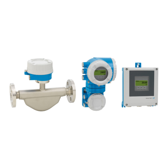
Product description Proline Promass F 500 Modbus RS485 Product description The measuring system consists of a transmitter and a sensor. The transmitter and sensor are mounted in physically separate locations. They are interconnected by one connecting cable(s). Product design Two versions of the transmitter are available. -
Page 15: Proline 500
Proline Promass F 500 Modbus RS485 Product description 3.1.2 Proline 500 Signal transmission: analog Order code for "Integrated ISEM electronics", option B "Transmitter" For use in applications required to meet special requirements due to ambient or operating conditions. As the electronics are located in the transmitter, the device is ideal in the event of: •... -
Page 16: Identification
A0029318 • If one of the conditions is not satisfied, contact your Endress+Hauser Sales Center. • Depending on the device version, the CD-ROM might not be part of the delivery! The Technical Documentation is available via the Internet or via the Endress+Hauser Operations App, see the "Product identification"... -
Page 17: Product Identification
• Enter the serial number from the nameplates into the Endress+Hauser Operations App or scan the 2-D matrix code (QR code) on the nameplate with the Endress+Hauser Operations App: all the information for the measuring device is displayed. For an overview of the scope of the associated Technical Documentation, refer to the following: •... - Page 18 Incoming acceptance and product identification Proline Promass F 500 Modbus RS485 Proline 500 3 4 5 Order code: Ser. no.: Ext. ord. cd.: Date: A0029192 4 Example of a transmitter nameplate Manufacturing location Name of the transmitter Order code Serial number (ser.
-
Page 19: Sensor Nameplate
Proline Promass F 500 Modbus RS485 Incoming acceptance and product identification 4.2.2 Sensor nameplate Order code: Ser. no.: Ext. ord. cd.: Date: A0029199 5 Example of a sensor nameplate Name of the sensor Manufacturing location Order code Serial number (ser. no.) Extended order code (Ext. -
Page 20: Symbols On Measuring Device
Incoming acceptance and product identification Proline Promass F 500 Modbus RS485 4.2.3 Symbols on measuring device Symbol Meaning WARNING! This symbol alerts you to a dangerous situation. Failure to avoid this situation can result in serious or fatal injury. Reference to documentation Refers to the corresponding device documentation. -
Page 21: Storage And Transport
Proline Promass F 500 Modbus RS485 Storage and transport Storage and transport Storage conditions Observe the following notes for storage: • Store in the original packaging to ensure protection from shock. • Do not remove protective covers or protective caps installed on process connections. -
Page 22: Measuring Devices With Lifting Lugs
Installation Proline Promass F 500 Modbus RS485 5.2.2 Measuring devices with lifting lugs CAUTION Special transportation instructions for devices with lifting lugs ‣ Only use the lifting lugs fitted on the device or flanges to transport the device. ‣ The device must always be secured at two lifting lugs at least. - Page 23 Proline Promass F 500 Modbus RS485 Installation To prevent measuring errors arising from accumulation of gas bubbles in the measuring tube, avoid the following mounting locations in the pipe: • Highest point of a pipeline. • Directly upstream of a free pipe outlet in a down pipe.
- Page 24 Installation Proline Promass F 500 Modbus RS485 Orientation Recommendation Vertical orientation A0015591 Horizontal orientation, transmitter at Exceptions: → 7, 24 A0015589 Horizontal orientation, transmitter at bottom Exceptions: → 7, 24 A0015590 Horizontal orientation, transmitter at side A0015592 Applications with low process temperatures may decrease the ambient temperature.
-
Page 25: Process
If operating outdoors: Avoid direct sunlight, particularly in warm climatic regions. You can order a weather protection cover from Endress+Hauser : → 178 System pressure It is important that cavitation does not occur, or that gases entrained in the liquids do not outgas. - Page 26 Installation Proline Promass F 500 Modbus RS485 NOTICE The insulation can also be thicker than the maximum recommended insulation thickness. Prerequisite: ‣ Ensure that convection takes place on a sufficiently large scale at the transmitter neck. ‣ Ensure that a sufficiently large area of the housing support remains exposed. The uncovered part serves as a radiator and protects the electronics from overheating and excessive cooling.
- Page 27 Proline Promass F 500 Modbus RS485 Installation 40(104) 60(140) [°C] [°F] A0028906 Insulation thickness Medium temperature Maximum recommended insulation thickness at an ambient temperature of T = 40 °C (104 °F) (104) Maximum recommended insulation thickness at an ambient temperature of T = 60 °C (140 °F)
-
Page 28: Special Mounting Instructions
Installation Proline Promass F 500 Modbus RS485 NOTICE Danger of overheating when heating ‣ Ensure that the temperature at the lower end of the transmitter housing does not exceed 80 °C (176 °F). ‣ Ensure that convection takes place on a sufficiently large scale at the transmitter neck. - Page 29 Proline Promass F 500 Modbus RS485 Installation DN 8 ( ")...150 (6") DN 250 (10") ⁄ RUPTURE DISK A0028903 Rupture disk label Rupture disk with 1/2" NPT internal thread with 1" width across flat Transport protection WARNING Limited functional reliability of the rupture disk.
- Page 30 Installation Proline Promass F 500 Modbus RS485 Protective cover 213 (8.4) 203 (8.0) A0029552 9 Weather protection cover for Proline 500 – digital 280 (11.0) 270 (10.5) A0029553 10 Weather protection cover for Proline 500 Cover locking: Proline 500 NOTICE Order code for "Housing", option L "Cast, stainless": The covers of the transmitter...
-
Page 31: Mounting The Measuring Device
Proline Promass F 500 Modbus RS485 Installation SW 2.5 5 (0.2) min. 15 (0.6) A0029799 Cover borehole for the securing screw Securing screw to lock the cover Mounting the measuring device 6.2.1 Required tools For transmitter For mounting on a post: •... -
Page 32: Proline 500 – Digital
Installation Proline Promass F 500 Modbus RS485 2. Install the measuring device or turn the transmitter housing so that the cable entries do not point upwards. A0029263 6.2.4 Mounting the transmitter housing: Proline 500 – digital CAUTION Ambient temperature too high! Danger of electronics overheating and housing deformation. -
Page 33: Proline 500
Proline Promass F 500 Modbus RS485 Installation Wall mounting 17 (0.67) 14 (0.55) 5.8 (0.23) 5.8 (0.23) 149 (5.85) A0029054 12 Engineering unit mm (in) 1. Drill the holes. 2. Insert wall plugs into the drilled holes. 3. Screw in the securing screws slightly at first. -
Page 34: Proline 500
Installation Proline Promass F 500 Modbus RS485 20 70 … ( 0.79 to 2.75) SW 13 A0029057 13 Engineering unit mm (in) Wall mounting 18 (0.71) 10 (0.39) 20 (0.79) 100 (3.94) A0029068 14 Engineering unit mm (in) 1. -
Page 35: 6.2.7 Turning The Display Module: Proline
Proline Promass F 500 Modbus RS485 Installation – – 3 mm 4 mm A0029993 1. Loosen the securing clamp of the connection compartment cover. 2. Unscrew the connection compartment cover. 3. Release the fixing screw. 4. Turn the housing to the desired position. -
Page 36: Post-Installation Check
Installation Proline Promass F 500 Modbus RS485 Post-installation check Is the device undamaged (visual inspection)? Does the measuring device conform to the measuring point specifications? For example: • Process temperature → 196 • Process pressure (refer to the chapter on "Pressure-temperature ratings" of the "Technical Information"... -
Page 37: Electrical Connection
Proline Promass F 500 Modbus RS485 Electrical connection Electrical connection NOTICE The measuring device does not have an internal circuit breaker. ‣ For this reason, assign the measuring device a switch or power-circuit breaker so that the power supply line can be easily disconnected from the mains. - Page 38 Electrical connection Proline Promass F 500 Modbus RS485 Current output 0/4 to 20 mA Standard installation cable is sufficient. Pulse/frequency/switch output Standard installation cable is sufficient. Double pulse output Standard installation cable is sufficient. Relay output Standard installation cable is sufficient.
- Page 39 Proline Promass F 500 Modbus RS485 Electrical connection Operating temperature When mounted in a fixed position: –50 to +105 °C (–58 to +221 °F); when cable can move freely: –25 to +105 °C (–13 to +221 °F) Available cable length Fixed: 20 m (65 ft);...
-
Page 40: Terminal Assignment
Electrical connection Proline Promass F 500 Modbus RS485 Optionally available connecting cable Connecting cable for Ex Zone 1, Class I, Division 1, IIC, IIB Standard cable 2 × 2 × 0.5 mm (AWG 20) PVC cable with common shield (2 pairs, twisted pair) -
Page 41: Preparing The Measuring Device
Proline Promass F 500 Modbus RS485 Electrical connection 7.1.4 Preparing the measuring device Carry out the steps in the following order: 1. Mount the sensor and transmitter. 2. Connection housing, sensor: Connect connecting cable. 3. Transmitter: Connect connecting cable. 4. Transmitter: Connect signal cable and cable for supply voltage. -
Page 42: Digital
Electrical connection Proline Promass F 500 Modbus RS485 Connecting the measuring device: Proline 500 – digital NOTICE Limitation of electrical safety due to incorrect connection! ‣ Have electrical connection work carried out by correspondingly trained specialists only. ‣ Observe applicable federal/national installation codes and regulations. - Page 43 Proline Promass F 500 Modbus RS485 Electrical connection Connecting the sensor connection housing via terminals For the device version with the order code for "Sensor connection housing": • Option A "Aluminum coated" • Option L "Cast, stainless" 10 (0.4) 3 mm...
- Page 44 Electrical connection Proline Promass F 500 Modbus RS485 Connecting the sensor connection housing via terminals For the device version with the order code for "Sensor connection housing": Option B "Stainless" 10 (0.4) 8 mm 22 mm 24 mm A0029613 1. Release the securing screw of the housing cover.
- Page 45 Proline Promass F 500 Modbus RS485 Electrical connection Connecting the sensor connection housing via the connector For the device version with the order code for "Sensor connection housing": Option C "Ultra-compact hygienic, stainless" A0029615 1. Connect the protective ground. 2. Connect the connector.
- Page 46 Electrical connection Proline Promass F 500 Modbus RS485 Connecting the connecting cable to the transmitter TX 20 TX 20 10 (0.4) 22 mm 24 mm A0029597 1. Loosen the 4 fixing screws on the housing cover. 2. Open the housing cover.
-
Page 47: Supply Voltage Cable
Proline Promass F 500 Modbus RS485 Electrical connection 7.2.2 Connecting the signal cable and the supply voltage cable A0028200 Cable entry for supply voltage Cable entry for cable or connection of device plug for signal transmission Cable entry for cable or connection of device plug for signal transmission... - Page 48 Electrical connection Proline Promass F 500 Modbus RS485 WARNING Housing degree of protection may be voided due to insufficient sealing of the housing. ‣ Screw in the screw without using any lubricant. WARNING Excessive tightening torque applied to the fixing screws! Risk of damaging the plastic transmitter.
-
Page 49: Connecting The Connecting Cable
Proline Promass F 500 Modbus RS485 Electrical connection Connecting the measuring device: Proline 500 NOTICE Limitation of electrical safety due to incorrect connection! ‣ Have electrical connection work carried out by correspondingly trained specialists only. ‣ Observe applicable federal/national installation codes and regulations. - Page 50 Electrical connection Proline Promass F 500 Modbus RS485 Connecting the sensor connection housing via terminals For the device version with the order code for "Housing": Option L "Cast, stainless" 10 (0.4) 3 mm 22 mm 24 mm A0029612 1. Loosen the securing clamp of the housing cover.
- Page 51 Proline Promass F 500 Modbus RS485 Electrical connection Connecting the sensor connection housing via terminals For the device version with the order code for "Housing": Option B "Stainless" 10 (0.4) 8 mm 22 mm 24 mm A0029613 1. Release the securing screw of the housing cover.
- Page 52 Electrical connection Proline Promass F 500 Modbus RS485 Connecting the connecting cable to the transmitter 10 (0.4) 3 mm 22 mm 24 mm A0029592 1. Loosen the securing clamp of the connection compartment cover. 2. Unscrew the connection compartment cover.
-
Page 53: Supply Voltage Cable
Proline Promass F 500 Modbus RS485 Electrical connection 7.3.2 Connecting the signal cable and the supply voltage cable A0026781 Cable entry for supply voltage Cable entry for signal transmission, input/output 1 and 2 Cable entry for input/output signal transmission; Optional: connection of external WLAN antenna or service plug –... - Page 54 Electrical connection Proline Promass F 500 Modbus RS485 10 (0.4) mm (in) – A0029815 7. Push the cable through the cable entry . To ensure tight sealing, do not remove the sealing ring from the cable entry. 8. Strip the cable and cable ends. In the case of stranded cables, also fit ferrules.
-
Page 55: Ensure Potential Equalization
Proline Promass F 500 Modbus RS485 Electrical connection Removing a cable 3 (0.12) A0029598 16 Engineering unit mm (in) 1. To remove a cable from the terminal, use a flat-blade screwdriver to push the slot between the two terminal holes 2. - Page 56 Electrical connection Proline Promass F 500 Modbus RS485 Current output 4-20 mA 4...20 mA A0028758 18 Connection example for 4-20 mA current output (active) Automation system with current input (e.g. PLC) Analog display unit: observe maximum load Transmitter 4...20 mA A0028759 ...
- Page 57 Proline Promass F 500 Modbus RS485 Electrical connection Switch output A0028760 21 Connection example for switch output (passive) Automation system with switch input (e.g. PLC) Power supply Transmitter: Observe input values → 185 Double pulse output A0029280 22 Connection example for double pulse output (active) Automation system with double pulse input (e.g.
- Page 58 Electrical connection Proline Promass F 500 Modbus RS485 Relay output A0028760 24 Connection example for relay output (passive) Automation system with relay input (e.g. PLC) Power supply Transmitter: Observe input values → 187 Current input A0028915 25...
-
Page 59: Hardware Settings
Proline Promass F 500 Modbus RS485 Electrical connection Hardware settings 7.6.1 Setting the device address The device address must always be configured for a Modbus slave. The valid device addresses are in the range from 1 to 247. Each address may only be assigned once in a Modbus RS485 network. -
Page 60: Enabling The Terminating Resistor
Electrical connection Proline Promass F 500 Modbus RS485 Proline 500 transmitter Hardware addressing A0029634 Set the desired device address using the DIP switches in the connection compartment. A0029633 To switch addressing from software addressing to hardware addressing: set the DIP switch to On. -
Page 61: Ensuring The Degree Of Protection
Proline Promass F 500 Modbus RS485 Electrical connection Proline 500 – digital transmitter A0029675 1. Open the housing cover. 2. Remove the display module. 3. Fold open the terminal cover. 4. Switch DIP switch No. 3 to On. Proline 500 transmitter ‣... -
Page 62: Post-Connection Check
Electrical connection Proline Promass F 500 Modbus RS485 5. To ensure that moisture does not enter the cable entry: Route the cable so that it loops down before the cable entry ("water trap"). A0029278 6. Insert dummy plugs into unused cable entries. -
Page 63: Operation Options
Proline Promass F 500 Modbus RS485 Operation options Operation options Overview of operation options A0030213 Local operation via display module Computer with Web browser (e.g. Internet Explorer) or with operating tool (e.g. FieldCare, DeviceCare, AMS Device Manager, SIMATIC PDM) Mobile handheld terminal Control system (e.g. -
Page 64: Menu
Operation options Proline Promass F 500 Modbus RS485 Structure and function of the operating menu 8.2.1 Structure of the operating menu For an overview of the operating menu for experts: "Description of Device Parameters" document supplied with the device→ 210... -
Page 65: Operating Philosophy
Proline Promass F 500 Modbus RS485 Operation options 8.2.2 Operating philosophy The individual parts of the operating menu are assigned to certain user roles (operator, maintenance etc.). Each user role contains typical tasks within the device lifecycle. For custody transfer, once the device has been put into circulation or sealed, its operation is restricted. -
Page 66: Operational Display
Operation options Proline Promass F 500 Modbus RS485 Menu/parameter User role and tasks Content/meaning Expert function-oriented Tasks that require detailed Contains all the parameters of the device and makes it possible to access knowledge of the function of the these parameters directly using an access code. The structure of this menu is... - Page 67 Proline Promass F 500 Modbus RS485 Operation options Display area In the display area, each measured value is prefaced by certain symbol types for further description: Measured variable Measurement channel Diagnostic behavior number ↓ ↓ ↓ Example Appears only if a diagnostics event is present for this measured variable.
- Page 68 Operation options Proline Promass F 500 Modbus RS485 8.3.2 Navigation view In the submenu In the wizard /../Operation 0091-1 /../Select medium Access stat.disp Select medium Operator Liquid Locking status Display A0013993-EN A0013995-EN Navigation view Navigation path to current position Status area Display area for navigation Operating elements →...
- Page 69 Proline Promass F 500 Modbus RS485 Operation options Display area Menus Symbol Meaning Operation Appears: • In the menu next to the "Operation" selection • At the left in the navigation path in the Operation menu Setup Appears: • In the menu next to the "Setup" selection •...
- Page 70 Operation options Proline Promass F 500 Modbus RS485 8.3.3 Editing view Numeric editor Text editor User ABC_ DEFG HIJK LMNO PQRS TUVW A0013999 A0013941 Editing view Display area of the entered values Input mask Operating elements → 71 Input mask...
-
Page 71: Operating Elements
Proline Promass F 500 Modbus RS485 Operation options Selection of letters from a to z. abc _ … Selection of special characters. "'^ _ … ~& Confirms selection. Switches to the selection of the correction tools. Exits the input without applying the changes. -
Page 72: Opening The Context Menu
Operation options Proline Promass F 500 Modbus RS485 Meaning Enter key For operational display • Pressing the key briefly opens the operating menu. • Pressing the key for 2 s opens the context menu. In a menu, submenu • Pressing the key briefly: –... - Page 73 Proline Promass F 500 Modbus RS485 Operation options 2. Press + simultaneously. The context menu is closed and the operational display appears. Calling up the menu via the context menu 1. Open the context menu. 2. Press to navigate to the desired menu.
-
Page 74: Navigating And Selecting From List
Operation options Proline Promass F 500 Modbus RS485 8.3.6 Navigating and selecting from list Different operating elements are used to navigate through the operating menu. The navigation path is displayed on the left in the header. Icons are displayed in front of the individual menus. -
Page 75: Calling Up Help Text
Proline Promass F 500 Modbus RS485 Operation options The direct access code consists of a 4-digit number and the channel number, which identifies the channel of a process variable: e.g. 0914-1. In the navigation view, this appears on the right-hand side in the header of the selected parameter. -
Page 76: 8.3.9 Changing The Parameters
Operation options Proline Promass F 500 Modbus RS485 8.3.9 Changing the parameters For a description of the editing display - consisting of text editor and numeric editor - with symbols → 70, for a description of the operating elements → 71 Example: Changing the tag name in the "Tag description"... -
Page 77: Authorization
Proline Promass F 500 Modbus RS485 Operation options Ent. access code Invalid or out of range input value Min:0 Max:9999 A0014049-EN 8.3.10 User roles and related access authorization The two user roles "Operator" and "Maintenance" have different write access to the parameters if the customer defines a user-specific access code. -
Page 78: Browser
Operation options Proline Promass F 500 Modbus RS485 Local operation with touch control The keypad lock is switched on and off via the context menu. Switching on the keypad lock The keypad lock is switched on automatically: • Each time the device is restarted. - Page 79 Proline Promass F 500 Modbus RS485 Operation options Computer software Software Interface CDI-RJ45 WLAN Recommended operating • Microsoft Windows 7 or higher. systems • Mobile operating systems: – iOS – Android Microsoft Windows XP is supported. Web browsers supported •...
-
Page 80: Establishing A Connection
Operation options Proline Promass F 500 Modbus RS485 8.4.3 Establishing a connection Via service interface (CDI-RJ45) Configuring the Internet protocol of the computer The following information refers to the default Ethernet settings of the device. IP address of the device: 192.168.1.212 (factory setting) 1. -
Page 81: Logging On
Proline Promass F 500 Modbus RS485 Operation options Starting the Web browser 1. Start the Web browser on the computer. 2. Enter the IP address of the Web server in the address line of the Web browser: 192.168.1.212 The login page appears. -
Page 82: User Interface
Operation options Proline Promass F 500 Modbus RS485 8.4.5 User interface A0029418 Function row Operating language Navigation area Header The following information appears in the header: • Device tag • Device status with status signal → 161 • Current measured values... -
Page 83: Disabling The Web Server
Proline Promass F 500 Modbus RS485 Operation options Working area Depending on the selected function and the related submenus, various actions can be performed in this area: • Configuring parameters • Reading measured values • Calling up help text • Starting an upload/download 8.4.6... -
Page 84: Connecting The Operating Tool
Operation options Proline Promass F 500 Modbus RS485 8.5.1 Connecting the operating tool Via Modbus RS485 protocol This communication interface is available in device versions with a Modbus-RS485 output. A0029437 29 Options for remote operation via Modbus-RS485 protocol (active) Control system (e.g. - Page 85 Proline Promass F 500 Modbus RS485 Operation options Proline 500 transmitter A0027563 31 Connection via service interface (CDI-RJ45) Computer with Web browser (e.g. Microsoft Internet Explorer, Microsoft Edge) for accessing the integrated device Web server or with "FieldCare", "DeviceCare" operating tool with COM DTM "CDI Communication TCP/IP"...
- Page 86 FieldCare Function scope FDT-based plant asset management tool from Endress+Hauser. It can configure all smart field devices in a system and helps you manage them. By using the status information, it is also a simple but effective way of checking their status and condition.
- Page 87 Display area for current measured values Edit toolbar with additional functions such as save/restore, event list and create documentation Navigation area with operating menu structure Working area Range of action Status area 8.5.3 DeviceCare Function scope Tool to connect and configure Endress+Hauser field devices. Endress+Hauser...
- Page 88 Operation options Proline Promass F 500 Modbus RS485 The fastest way to configure Endress+Hauser field devices is with the dedicated "DeviceCare" tool. Together with the device type managers (DTMs) it presents a convenient, comprehensive solution. For details, see Innovation Brochure IN01047S Source for device description files See information →...
-
Page 89: System Integration
Proline Promass F 500 Modbus RS485 System integration System integration Overview of device description files 9.1.1 Current version data for the device Firmware version 01.00.zz • On the title page of the Operating instructions • On the transmitter nameplate • Firmware version Diagnostics →... -
Page 90: Modbus Rs485 Information
System integration Proline Promass F 500 Modbus RS485 Compatible Modbus registers: diagnostic information Diagnostic information Compatible Modbus registers Diagnostic code (data type: String), e.g. F270 6821 Diagnostic number (data type: Integer), e.g. 270 6859 The Modbus registers are compatible but the diagnostic numbers are not. Overview of the new diagnostic numbers →... -
Page 91: Register Information
Proline Promass F 500 Modbus RS485 System integration Code Name Description Application Write multiple Master writes a new value to Write multiple device parameters registers multiple Modbus registers of the Example: device. • Mass flow unit A maximum of 120 consecutive •... - Page 92 System integration Proline Promass F 500 Modbus RS485 Scan list configuration For configuration, the Modbus RS485 register addresses of the device parameters to be grouped must be entered in the scan list. Please note the following basic requirements of the scan list: Max.
-
Page 93: Commissioning
Proline Promass F 500 Modbus RS485 Commissioning Commissioning 10.1 Function check Before commissioning the measuring device: ‣ Make sure that the post-installation and post-connection checks have been performed. • "Post-installation check" checklist → 36 • "Post-connection check" checklist → 62 10.2... -
Page 94: Defining The Tag Name
Commissioning Proline Promass F 500 Modbus RS485 ‣ Communication → 96 ‣ Medium selection → 98 ‣ I/O configuration → 99 ‣ Current input 1 to n → 100 ‣ Status input 1 to n → 101 ‣... -
Page 95: 10.3.2 Setting The System Units
Proline Promass F 500 Modbus RS485 Commissioning Parameter overview with brief description Parameter Description User entry Factory setting Device tag Enter the name for the measuring point. Max. 32 characters such as Promass letters, numbers or special characters (e.g. @, %, /). -
Page 96: Interface
Commissioning Proline Promass F 500 Modbus RS485 Parameter Description Selection Factory setting Volume flow unit Select volume flow unit. Unit choose list Country-specific: • l/h Result • gal/min (us) The selected unit applies for: • Output • Low flow cut off •... - Page 97 Proline Promass F 500 Modbus RS485 Commissioning Navigation "Setup" menu → Communication ‣ Communication → 97 Bus address → 97 Baudrate Data transfer mode → 97 Parity → 97 Byte order → 97 Failure mode →...
- Page 98 Commissioning Proline Promass F 500 Modbus RS485 10.3.4 Selecting and setting the medium The Select medium wizard submenu contains parameters that must be configured in order to select and set the medium. Navigation "Setup" menu → Select medium ‣ Medium selection →...
- Page 99 Proline Promass F 500 Modbus RS485 Commissioning Parameter overview with brief description Parameter Prerequisite Description Selection / User Factory setting entry Select medium – Select medium type. • Liquid Liquid • Gas Select gas type The Gas option is selected in Select measured gas type.
-
Page 100: Configuring The Current Input
Commissioning Proline Promass F 500 Modbus RS485 Navigation "Setup" menu → I/O configuration ‣ I/O configuration → 100 I/O module 1 to n terminal numbers → 100 I/O module 1 to n information I/O module 1 to n type →... -
Page 101: Configuring The Status Input
Proline Promass F 500 Modbus RS485 Commissioning Signal mode → 101 0/4 mA value → 101 20 mA value → 101 Current span → 101 Failure mode → 101 → 101 Failure value Parameter overview with brief description... -
Page 102: Configuring The Current Output
Commissioning Proline Promass F 500 Modbus RS485 Navigation "Setup" menu → Status input ‣ Status input 1 to n → 102 Assign status input → 102 Terminal number Active level → 102 Terminal number → 102 Response time status input →... - Page 103 Proline Promass F 500 Modbus RS485 Commissioning Assign current output 1 to n → 103 Current span → 103 0/4 mA value → 104 20 mA value → 104 Fixed current → 104 → 104...
- Page 104 Commissioning Proline Promass F 500 Modbus RS485 Parameter Prerequisite Description Selection / User Factory setting interface / User entry 0/4 mA value One of the following options is Enter 4 mA value. Signed floating-point Country-specific: selected in the Current span number • 0 kg/h parameter (→...
-
Page 105: Switch Output
Proline Promass F 500 Modbus RS485 Commissioning 10.3.9 Configuring the pulse/frequency/switch output The Pulse/frequency/switch output wizard guides you systematically through all the parameters that can be set for configuring the selected output type. Navigation "Setup" menu → Advanced setup → Pulse/frequency/switch output ‣... - Page 106 Commissioning Proline Promass F 500 Modbus RS485 Parameter overview with brief description Parameter Prerequisite Description Selection / User Factory setting interface / User entry Operating mode – Define the output as a pulse, • Pulse Pulse frequency or switch output. • Frequency • Switch Terminal number –...
- Page 107 Proline Promass F 500 Modbus RS485 Commissioning Configuring the frequency output Navigation "Setup" menu → Pulse/frequency/switch output ‣ Pulse/frequency/switch output 1 to n Operating mode → 107 Terminal number → 107 Signal mode → 107 → 108...
- Page 108 Commissioning Proline Promass F 500 Modbus RS485 Parameter Prerequisite Description Selection / User Factory setting interface / User entry Assign frequency output In the Operating mode Select process variable for • Off parameter (→ 105), the frequency output. • Mass flow Frequency option is selected.
- Page 109 Proline Promass F 500 Modbus RS485 Commissioning Parameter Prerequisite Description Selection / User Factory setting interface / User entry Maximum frequency value In the Operating mode Enter maximum frequency. 0.0 to 10 000.0 Hz 10 000.0 Hz parameter, the Frequency option is selected and one of...
- Page 110 Commissioning Proline Promass F 500 Modbus RS485 Parameter Prerequisite Description Selection / User Factory setting interface / User entry Measuring value at maximum In the Operating mode Enter measured value for Signed floating-point Depends on country frequency parameter, the Frequency maximum frequency. number and nominal...
- Page 111 Proline Promass F 500 Modbus RS485 Commissioning Parameter Prerequisite Description Selection / User Factory setting interface / User entry Failure frequency In the Operating mode Enter frequency output value 0.0 to 12 500.0 Hz 0.0 Hz parameter, the Frequency in alarm condition. option is selected and one of...
- Page 112 Commissioning Proline Promass F 500 Modbus RS485 Configuring the switch output Navigation "Setup" menu → Pulse/frequency/switch output ‣ Pulse/frequency/switch output 1 to n Operating mode → 112 Terminal number → 112 Signal mode → 112 → 113...
- Page 113 Proline Promass F 500 Modbus RS485 Commissioning Parameter Prerequisite Description Selection / User Factory setting interface / User entry Switch output function In the Operating mode Select function for switch • Off parameter the Switch option is output. • On selected. • Diagnostic behavior •...
-
Page 114: Configuring The Relay Output
Commissioning Proline Promass F 500 Modbus RS485 Parameter Prerequisite Description Selection / User Factory setting interface / User entry Switch-off delay • The Switch option is Define delay for the switch-off 0.0 to 100.0 s 0.0 s selected in the Operating of status output. - Page 115 Proline Promass F 500 Modbus RS485 Commissioning Parameter overview with brief description Parameter Prerequisite Description Selection / User Factory setting interface / User entry Relay output function – Select the function for the • Closed Closed relay output. • Open • Diagnostic behavior • Limit •...
- Page 116 Commissioning Proline Promass F 500 Modbus RS485 10.3.11 Configuring the double pulse output The Double pulse output submenu guides the user systematically through all the parameters that have to be set for configuring the double pulse output. Navigation "Setup" menu → Double pulse output ‣...
-
Page 117: Configuring The Local Display
Proline Promass F 500 Modbus RS485 Commissioning Parameter Description Selection / User interface / Factory setting User entry Failure mode Define output behavior in alarm condition. • Actual value No pulses • No pulses Invert output signal Invert the output signal. • No •... - Page 118 Commissioning Proline Promass F 500 Modbus RS485 Parameter overview with brief description Parameter Prerequisite Description Selection / User Factory setting entry Format display A local display is provided. Select how measured values • 1 value, max. size 1 value, max. size are shown on the display.
- Page 119 Proline Promass F 500 Modbus RS485 Commissioning Parameter Prerequisite Description Selection / User Factory setting entry Value 2 display A local display is provided. Select the measured value that • None None is shown on the local display. • Mass flow • Volume flow •...
-
Page 120: Configuring The Low Flow Cut Off
Commissioning Proline Promass F 500 Modbus RS485 10.3.13 Configuring the low flow cut off The Low flow cut off wizard systematically guides the user through all the parameters that must be set to configure low flow cut off. Navigation "Setup" menu → Low flow cut off ‣... -
Page 121: 10.3.14 Configuring The Partial Filled Pipe
Proline Promass F 500 Modbus RS485 Commissioning 10.3.14 Configuring the partial filled pipe detection The Partial filled pipe detection wizard guides you systematically through all parameters that have to be set for configuring the monitoring of the pipe filling. Navigation "Setup"... -
Page 122: Advanced Settings
Commissioning Proline Promass F 500 Modbus RS485 10.4 Advanced settings The Advanced setup submenu together with its submenus contains parameters for specific settings. Navigation to the "Advanced setup" submenu X X X X X X X 20.50 0104-1 Main menu... -
Page 123: Calculated Values
Proline Promass F 500 Modbus RS485 Commissioning ‣ Custody transfer deactivation ‣ Display → 127 ‣ WLAN settings → 130 ‣ Concentration ‣ Heartbeat setup ‣ Configuration backup → 131 ‣ Administration → 133 10.4.1 Calculated values The Calculated values submenu contains parameters for calculating the corrected volume flow. -
Page 124: Carrying Out A Sensor Adjustment
Commissioning Proline Promass F 500 Modbus RS485 Parameter overview with brief description Parameter Prerequisite Description Selection / User Factory setting interface / User entry Corrected volume flow calculation – Select reference density for • Fixed reference Calculated reference calculating the corrected density density volume flow. -
Page 125: Configuring The Totalizer
Proline Promass F 500 Modbus RS485 Commissioning Parameter overview with brief description Parameter Description Selection Factory setting Installation direction Set sign of flow direction to match the • Flow in arrow direction Flow in arrow direction direction of the arrow on the sensor. - Page 126 Commissioning Proline Promass F 500 Modbus RS485 Parameter overview with brief description Parameter Prerequisite Description Selection Factory setting Assign process variable – Select process variable for • Off Mass flow totalizer. • Volume flow • Mass flow • Corrected volume flow •...
-
Page 127: Configurations
Proline Promass F 500 Modbus RS485 Commissioning 10.4.4 Carrying out additional display configurations In the Display submenu you can set all the parameters associated with the configuration of the local display. Navigation "Setup" menu → Advanced setup → Display ‣... - Page 128 Commissioning Proline Promass F 500 Modbus RS485 Parameter overview with brief description Parameter Prerequisite Description Selection / User Factory setting entry Format display A local display is provided. Select how measured values • 1 value, max. size 1 value, max. size are shown on the display.
- Page 129 Proline Promass F 500 Modbus RS485 Commissioning Parameter Prerequisite Description Selection / User Factory setting entry Value 2 display A local display is provided. Select the measured value that • None None is shown on the local display. • Mass flow • Volume flow •...
-
Page 130: Wlan Configuration
Commissioning Proline Promass F 500 Modbus RS485 Parameter Prerequisite Description Selection / User Factory setting entry Decimal places 4 A measured value is specified Select the number of decimal • x x.xx in the Value 4 display places for the display value. -
Page 131: Configuration Management
Proline Promass F 500 Modbus RS485 Commissioning Navigation "Setup" menu → Advanced setup → WLAN Settings ‣ WLAN settings → 131 WLAN IP address → 131 Security type WLAN passphrase → 131 Assign SSID name → 131 SSID name →... - Page 132 Commissioning Proline Promass F 500 Modbus RS485 Navigation "Setup" menu → Advanced setup → Configuration backup ‣ Configuration backup → 132 Operating time → 132 Last backup Configuration management → 132 Backup state → 132 Comparison result →...
-
Page 133: Using Parameters For Device Administration
Proline Promass F 500 Modbus RS485 Commissioning Options Description Compare The device configuration saved in the device memory is compared with the current device configuration of the integrated HistoROM. Clear backup data The backup copy of the device configuration is deleted from the memory of the device. -
Page 134: Simulation
Commissioning Proline Promass F 500 Modbus RS485 Using the parameter to reset the access code Navigation "Setup" menu → Advanced setup → Administration → Reset access code ‣ Reset access code Operating time → 134 Reset access code → 134... - Page 135 Proline Promass F 500 Modbus RS485 Commissioning Process variable value → 136 Status input simulation → 136 Input signal level → 136 Current input 1 to n simulation → 136 Value current input 1 to n →...
- Page 136 Commissioning Proline Promass F 500 Modbus RS485 Parameter overview with brief description Parameter Prerequisite Description Selection / User Factory setting entry / User interface Assign simulation process variable – Select a process variable for • Off the simulation process that is • Mass flow activated.
-
Page 137: Access
Proline Promass F 500 Modbus RS485 Commissioning Parameter Prerequisite Description Selection / User Factory setting entry / User interface Switch output simulation 1 to n In the Operating mode Switch the simulation of the • Off parameter, the Switch option switch output on and off. - Page 138 Commissioning Proline Promass F 500 Modbus RS485 Defining the access code via local display 1. Navigate to the Define access code parameter (→ 133). 2. Define a max. 16-digit character string comprising numbers, letters and special characters as the access code.
-
Page 139: Switch
Proline Promass F 500 Modbus RS485 Commissioning Via Web browser, FieldCare, DeviceCare (via CDI-RJ45 service interface), fieldbus For a reset code, contact your Endress+Hauser service organization. 1. Navigate to the Reset access code parameter (→ 134). 2. Enter the reset code. - Page 140 Commissioning Proline Promass F 500 Modbus RS485 4. Setting the write protection (WP) switch on the main electronics module to the ON position enables hardware write protection. In the Locking status parameter the Hardware locked option is displayed → 141. In addition, on the local display the -symbol appears in front of the parameters in the header of the operational display and in the navigation view.
-
Page 141: Operation
Proline Promass F 500 Modbus RS485 Operation Operation 11.1 Reading the device locking status Device active write protection: Locking status parameter Operation → Locking status Function scope of the "Locking status" parameter Options Description None The access status displayed in the Access status parameter applies → 77. Only appears on local display. - Page 142 Operation Proline Promass F 500 Modbus RS485 ‣ Output values → 145 ‣ Totalizer → 143 11.4.1 "Measured variables" submenu The Measured variables submenu contains all the parameters needed to display the current measured values for each process variable.
- Page 143 Proline Promass F 500 Modbus RS485 Operation Parameter Prerequisite Description User interface Corrected volume flow – Displays the corrected volume flow Signed floating-point currently calculated. number Dependency The unit is taken from the Corrected volume flow unit parameter (→ 96).
- Page 144 Operation Proline Promass F 500 Modbus RS485 Navigation "Diagnostics" menu → Measured values → Totalizer ‣ Totalizer → 144 Totalizer value 1 to n → 144 Totalizer overflow 1 to n Parameter overview with brief description Parameter Prerequisite...
- Page 145 Proline Promass F 500 Modbus RS485 Operation Parameter overview with brief description Parameter Description User interface Measured values 1 to n Displays the current input value. Signed floating-point number Measured current 1 to n Displays the current value of the current input.
- Page 146 Operation Proline Promass F 500 Modbus RS485 Navigation "Diagnostics" menu → Measured values → Output values → Value current output 1 to n ‣ Current output 1 to n → 146 Output current 1 to n → 146...
- Page 147 Proline Promass F 500 Modbus RS485 Operation Parameter overview with brief description Parameter Prerequisite Description User interface / User Factory setting entry Output frequency In the Operating mode Displays the value currently 0.0 to 12 500.0 Hz – parameter, the Frequency measured for the frequency option is selected.
-
Page 148: Conditions
Operation Proline Promass F 500 Modbus RS485 Navigation "Diagnostics" menu → Measured values → Output values → Double pulse output ‣ Double pulse output → 148 Pulse output Parameter overview with brief description Parameter Description User interface Pulse output Shows the currently output pulse frequency. -
Page 149: Function Scope Of The "Control Totalizer" Parameter
Proline Promass F 500 Modbus RS485 Operation Parameter overview with brief description Parameter Prerequisite Description Selection / User Factory setting entry Control Totalizer 1 to n One of the following options is Control totalizer value. • Totalize Totalize selected in the Assign process •... - Page 150 Operation Proline Promass F 500 Modbus RS485 Function range • A total of 1000 measured values can be stored • 4 logging channels • Adjustable logging interval for data logging • Display of the measured value trend for each logging channel in the form of a chart A0016357 ...
- Page 151 Proline Promass F 500 Modbus RS485 Operation Parameter overview with brief description Parameter Prerequisite Description Selection / User Factory setting entry / User interface Assign channel 1 to n The Extended HistoROM Assign process variable to • Off application package is logging channel. • Mass flow available.
-
Page 152: Diagnostics And Troubleshooting
Diagnostics and troubleshooting Proline Promass F 500 Modbus RS485 Diagnostics and troubleshooting 12.1 General troubleshooting For local display Error Possible causes Solution Local display dark and no output Supply voltage does not match the Apply the correct supply voltage . - Page 153 Proline Promass F 500 Modbus RS485 Diagnostics and troubleshooting For output signals Error Possible causes Solution Signal output outside the valid Main electronics module is Order spare part → 176. range defective. Device shows correct value on local Configuration error...
-
Page 154: Transmitter
Diagnostics and troubleshooting Proline Promass F 500 Modbus RS485 Error Possible causes Solution Web browser frozen and operation Data transfer active Wait until data transfer or current no longer possible action is finished. Connection lost 1. Check cable connection and power supply. - Page 155 Proline Promass F 500 Modbus RS485 Diagnostics and troubleshooting A0029689 Supply voltage Device status Not used Communication Service interface (CDI) active 1. Open the housing cover. 2. Remove the display module. 3. Fold open the terminal cover. Color Meaning Supply voltage...
- Page 156 Diagnostics and troubleshooting Proline Promass F 500 Modbus RS485 1 2 3 4 5 A0029629 Supply voltage Device status Not used Communication Service interface (CDI) active Color Meaning Supply voltage Supply voltage is off or too low Green Supply voltage is ok...
- Page 157 Proline Promass F 500 Modbus RS485 Diagnostics and troubleshooting Communication Communication Alarm Power Power A0029699 Communication Device status Supply voltage Color Meaning Communication White Communication active Device status Error Flashing red Warning Supply voltage Green Supply voltage is ok Supply voltage is off or too low...
-
Page 158: Diagnostic Message
Diagnostics and troubleshooting Proline Promass F 500 Modbus RS485 12.3 Diagnostic information on local display 12.3.1 Diagnostic message Faults detected by the self-monitoring system of the measuring device are displayed as a diagnostic message in alternation with the operational display. - Page 159 Proline Promass F 500 Modbus RS485 Diagnostics and troubleshooting Diagnostic behavior Symbol Meaning Alarm • Measurement is interrupted. • Signal outputs and totalizers assume the defined alarm condition. • A diagnostic message is generated. Warning Measurement is resumed. The signal outputs and totalizers are not affected. A diagnostic message is generated.
-
Page 160: Calling Up Remedial Measures
Diagnostics and troubleshooting Proline Promass F 500 Modbus RS485 12.3.2 Calling up remedial measures X X X X X X X X X X X X X X 20.50 S801 Supply voltage Menu Diagnostic list Diagnostics 1 S801 Supply voltage... -
Page 161: Fieldcare
Proline Promass F 500 Modbus RS485 Diagnostics and troubleshooting A0031056 Status area with status signal Diagnostic information→ 159 Remedy information with Service ID In addition, diagnostic events which have occurred can be shown in the Diagnostics menu: • Via parameter •... - Page 162 Diagnostics and troubleshooting Proline Promass F 500 Modbus RS485 Xxxxxx/…/…/ Device name: Xxxxxxx Mass flow: kg/h 12.34 Device tag: Xxxxxxx Volume flow: 12.34 m /h ³ Status signal: Function check (C) Xxxxxx Diagnostics 1: C485 Simu... Remedy information: Deactivate... Failure (F)
-
Page 163: Adapting The Diagnostic Information
Proline Promass F 500 Modbus RS485 Diagnostics and troubleshooting The user is in the Diagnostics menu. 1. Call up the desired parameter. 2. On the right in the working area, mouse over the parameter. A tool tip with remedy information for the diagnostic event appears. -
Page 164: Overview Of Diagnostic Information
Diagnostics and troubleshooting Proline Promass F 500 Modbus RS485 Options Description Logbook entry only The device continues to measure. The diagnostic message is displayed only in the Event logbook submenu (Event list submenu) and is not displayed in alternation with the operational display. - Page 165 Proline Promass F 500 Modbus RS485 Diagnostics and troubleshooting Diagnostic Short text Remedy instructions Status Diagnostic number signal behavior [from the [from the factory] factory] Modules incompatible 1. Check electronic modules Alarm 2. Change electronic modules Sensor electronic 1. Check or replace connection cable...
- Page 166 Diagnostics and troubleshooting Proline Promass F 500 Modbus RS485 Diagnostic Short text Remedy instructions Status Diagnostic number signal behavior [from the [from the factory] factory] Diagnostic of configuration I/O 1 to n configuration 1. Apply I/O module configuration Warning changed...
- Page 167 Proline Promass F 500 Modbus RS485 Diagnostics and troubleshooting Diagnostic Short text Remedy instructions Status Diagnostic number signal behavior [from the [from the factory] factory] I/O 1 to n hardware 1. Check I/O hardware configuration Alarm configuration invalid 2. Replace wrong I/O module 3.
-
Page 168: Pending Diagnostic Events
Diagnostics and troubleshooting Proline Promass F 500 Modbus RS485 Diagnostic Short text Remedy instructions Status Diagnostic number signal behavior [from the [from the factory] factory] Monitoring failed Check process conditions for Warning Heartbeat Monitoring Oscillation damping too Check process conditions... -
Page 169: Diagnostic List
Proline Promass F 500 Modbus RS485 Diagnostics and troubleshooting Parameter Prerequisite Description User interface Operating time from restart – Shows the time the device has been in Days (d), hours (h), operation since the last device restart. minutes (m) and seconds Operating time –... -
Page 170: Filtering The Event Logbook
Diagnostics and troubleshooting Proline Promass F 500 Modbus RS485 In addition to the operation time of its occurrence, each event is also assigned a symbol that indicates whether the event has occurred or is ended: • Diagnostic event – : Occurrence of the event –... - Page 171 Proline Promass F 500 Modbus RS485 Diagnostics and troubleshooting Info number Info name I1256 Display: access status changed I1278 I/O module reset detected I1335 Firmware changed I1361 Web server login failed I1397 Fieldbus: access status changed I1398 CDI: access status changed...
-
Page 172: Resetting The Measuring Device
Diagnostics and troubleshooting Proline Promass F 500 Modbus RS485 Info number Info name I1651 Custody transfer parameter changed I1712 New flash file received I1725 Sensor electronic module (ISEM) changed I1726 Configuration backup failed 12.12 Resetting the measuring device Using theDevice reset parameter (→ 134) it is possible to reset the entire device configuration or some of the configuration to a defined state. - Page 173 Proline Promass F 500 Modbus RS485 Diagnostics and troubleshooting Extended order code 3 → 173 ENP version → 173 Parameter overview with brief description Parameter Description User interface Factory setting Device tag Shows name of measuring point. Max. 32 characters, such as...
-
Page 174: Firmware History
"Manufacturer' s information" document. The manufacturer' s information is available: • In the Download Area of the Endress+Hauser web site: www.endress.com → Downloads • Specify the following details: –... -
Page 175: Maintenance
→ 196. 13.2 Measuring and test equipment Endress+Hauser offers a wide variety of measuring and test equipment, such as W@M or device tests. Your Endress+Hauser Sales Center can provide detailed information on the services. List of some of the measuring and testing equipment: → 178 13.3... -
Page 176: Repairs
• The measuring devices have a modular design. • Spare parts are grouped into logical kits with the associated Installation Instructions. • Repairs are carried out by Endress+Hauser Service or by appropriately trained customers. • Certified devices can only be converted to other certified devices by Endress+Hauser Service or at the factory. -
Page 177: Disposal
Proline Promass F 500 Modbus RS485 Repairs 14.5 Disposal 14.5.1 Removing the measuring device 1. Switch off the device. WARNING Danger to persons from process conditions. ‣ Beware of hazardous process conditions such as pressure in the measuring device, high temperatures or aggressive fluids. -
Page 178: Accessories
Various accessories, which can be ordered with the device or subsequently from Endress +Hauser, are available for the device. Detailed information on the order code in question is available from your local Endress+Hauser sales center or on the product page of the Endress+Hauser website: www.endress.com. -
Page 179: For The Sensor
Is used to stabilize the temperature of the fluids in the sensor. Water, water vapor and other non-corrosive liquids are permitted for use as fluids. If using oil as a heating medium, please consult with Endress+Hauser. Heating jackets cannot be used with sensors fitted with a rupture disk. - Page 180 Accessories Proline Promass F 500 Modbus RS485 Cerabar S The pressure transmitter for measuring the absolute and gauge pressure of gases, steam and liquids. It can be used to read in the operating pressure value. For details, see "Technical Information" TI00383P and Operating Instructions...
-
Page 181: Technical Data
Proline Promass F 500 Modbus RS485 Technical data Technical data 16.1 Application The measuring device is suitable for flow measurement of liquids and gases only. Depending on the version ordered, the measuring device can also measure potentially explosive, flammable, poisonous and oxidizing media. -
Page 182: Input
Technical data Proline Promass F 500 Modbus RS485 16.3 Input Measured variable Direct measured variables • Mass flow • Density • Temperature Calculated measured variables • Volume flow • Corrected volume flow • Reference density Measuring range Measuring ranges for liquids Measuring range full scale values ... - Page 183 • Operating pressure to increase accuracy (Endress+Hauser recommends the use of a pressure measuring device for absolute pressure, e.g. Cerabar M or Cerabar S) •...
- Page 184 Technical data Proline Promass F 500 Modbus RS485 Voltage drop Typically: 0.6 to 2 V for 3.6 to 22 mA (passive) Maximum input voltage ≤ 30 V (passive) Open-circuit voltage ≤ 28.8 V (active) Possible input variables • Pressure • Temperature •...
-
Page 185: Output
Proline Promass F 500 Modbus RS485 Technical data 16.4 Output Output signal Modbus RS485 Physical interface RS485 in accordance with EIA/TIA-485 standard Terminating resistor Integrated, can be activated via DIP switches Current output 0/4 to 20 mA Current output 0/4 to 20 mA Maximum output values 22.5 mA... - Page 186 Technical data Proline Promass F 500 Modbus RS485 Assignable measured • Mass flow variables • Volume flow • Corrected volume flow • Density • Reference density • Temperature Frequency output Maximum input values DC 30 V, 250 mA (passive) Maximum output current 22.5 mA (active)
- Page 187 Proline Promass F 500 Modbus RS485 Technical data Voltage drop For 22.5 mA: ≤ DC 2 V Output frequency Adjustable: 0 to 1 000 Hz Damping Adjustable: 0 to 999 s Pulse/pause ratio Assignable measured • Mass flow variables • Volume flow •...
- Page 188 Technical data Proline Promass F 500 Modbus RS485 Modbus RS485 Failure mode Choose from: • NaN value instead of current value • Last valid value Current output 0/4 to 20 mA 4 to 20 mA Failure mode Choose from: • 4 to 20 mA in accordance with NAMUR recommendation NE 43 •...
-
Page 189: Power Supply
Proline Promass F 500 Modbus RS485 Technical data Light emitting diodes (LED) Status information Status indicated by various light emitting diodes The following information is displayed depending on the device version: • Supply voltage active • Data transmission active • Device alarm/error has occurred ... -
Page 190: Performance Characteristics
Technical data Proline Promass F 500 Modbus RS485 Supply voltage Order code for terminal voltage Frequency range "Power supply" Option D DC 24 V ±20% – Option E AC100 to 240 V –15…+10% 50/60 Hz DC 24 V ±20% –... - Page 191 Proline Promass F 500 Modbus RS485 Technical data Base accuracy Design fundamentals → 194 Mass flow and volume flow (liquids) ±0.05 % o.r. (PremiumCal; order code for "Calibration flow", option D, for mass flow) ±0.10 % o.r. Mass flow (gases) ±0.35 % o.r.
- Page 192 Technical data Proline Promass F 500 Modbus RS485 SI units 1:10 1:20 1:50 1:100 1:500 [mm] [kg/h] [kg/h] [kg/h] [kg/h] [kg/h] [kg/h] 2 000 6 500 18 000 1 800 45 000 4 500 2 250 70 000 7 000...
- Page 193 Proline Promass F 500 Modbus RS485 Technical data Mass flow (gases) ±0.25 % o.r. Design fundamentals → 194 Density (liquids) ±0.00025 g/cm Temperature ±0.25 °C ± 0.0025 · T °C (±0.45 °F ± 0.0015 · (T–32) °F) Response time The response time depends on the configuration (damping).
- Page 194 Technical data Proline Promass F 500 Modbus RS485 Temperature ±0.005 · T °C (± 0.005 · (T – 32) °F) Influence of medium The table below shows the effect on accuracy of mass flow due to a difference between pressure calibration pressure and process pressure.
-
Page 195: Installation
Proline Promass F 500 Modbus RS485 Technical data Example for max. measured error E [%] 100 Q [%] A0028808 Error: Maximum measured error as % o.r. (example using PremiumCal) Flow rate as % 16.7 Installation "Mounting requirements" → 22 16.8... -
Page 196: Process
Technical data Proline Promass F 500 Modbus RS485 Shock resistance Shock, half-sine according to IEC 60068-2-27 6 ms 30 g Impact resistance Rough handling shocks according to IEC 60068-2-31 Electromagnetic As per IEC/EN 61326 and NAMUR Recommendation 21 (NE 21) compatibility (EMC) For details, refer to the Declaration of Conformity. - Page 197 Proline Promass F 500 Modbus RS485 Technical data Pressure-temperature An overview of the pressure-temperature ratings for the process connections is ratings provided in the "Technical Information" document Secondary containment The sensor housing is filled with dry inert gas and protects the electronics and mechanics pressure rating inside.
-
Page 198: Mechanical Construction
Technical data Proline Promass F 500 Modbus RS485 Special mounting instructions: → 28 For information on the dimensions: see the "Mechanical construction" section of the "Technical Information" document Flow limit Select the nominal diameter by optimizing between the required flow range and permissible pressure loss. - Page 199 Proline Promass F 500 Modbus RS485 Technical data DN [mm] Weight [kg] Weight in US units DN [in] Weight [lbs] ½ 1½ Materials Transmitter housing Proline 500 – digital transmitter housing Order code for "Transmitter housing": • Option A "Aluminum coated": aluminum, AlSi10Mg, coated •...
- Page 200 Technical data Proline Promass F 500 Modbus RS485 Cable entries/cable glands A0020640 38 Possible cable entries/cable glands Cable entry with M20 × 1.5 internal thread Cable gland M20 × 1.5 Adapter for cable entry with internal thread G ½" or NPT ½"...
- Page 201 Proline Promass F 500 Modbus RS485 Technical data Sensor housing • Acid and alkali-resistant outer surface • DN 08 to DN 150: stainless steel, 1.4301 (304) Optional: order code for "Sensor option", option CC: stainless steel, 1.4404 (316L) • DN 250: –...
-
Page 202: Operability
Technical data Proline Promass F 500 Modbus RS485 Process connections • Fixed flange connections: – EN 1092-1 (DIN 2501) flange – EN 1092-1 (DIN 2512N) flange – Namur lengths in accordance with NE 132 – ASME B16.5 flange – JIS B2220 flange –... - Page 203 Proline Promass F 500 Modbus RS485 Technical data A0028232 39 Operation with touch control Proline 500 – digital Proline 500 Display elements • 4-line, illuminated, graphic display • White background lighting; switches to red in event of device errors •...
- Page 204 Technical data Proline Promass F 500 Modbus RS485 Supported operating Operating unit Interface Additional information tools Web browser Notebook, PC or tablet • CDI-RJ45 service Special Documentation for the with Web browser interface device → 211 • WLAN interface...
- Page 205 Proline Promass F 500 Modbus RS485 Technical data Additional information on the data storage concept There are different types of data storage units in which device data are stored and used by the device: Device memory T-DAT S-DAT Available data •...
- Page 206 EU Directives. These are listed in the corresponding EU Declaration of Conformity along with the standards applied. Endress+Hauser confirms successful testing of the device by affixing to it the CE mark. C-Tick symbol The measuring system meets the EMC requirements of the "Australian Communications and Media Authority (ACMA)".
- Page 207 The measuring device is qualified to OIML R117 or OIML R137 and has an OIML Certificate of Conformity (optional). Additional certification Marine approval Currently valid certificates are available: • In the Download Area of the Endress+Hauser Internet site: www.endress.com → Downloads • Specify the following details: Search area: Approval & Certificates→ Marine CRN approval Some device versions have CRN approval.
- Page 208 The application packages can be ordered with the device or subsequently from Endress+Hauser. Detailed information on the order code in question is available from your local Endress+Hauser sales center or on the product page of the Endress+Hauser website: www.endress.com.
- Page 209 Proline Promass F 500 Modbus RS485 Technical data Diagnostics functions Package Description Extended HistoROM Comprises extended functions concerning the event log and the activation of the measured value memory. Event log: Memory volume is extended from 20 message entries (standard version) to up to 100 entries.
- Page 210 • The W@M Device Viewer : Enter the serial number from the nameplate (www.endress.com/deviceviewer) • The Endress+Hauser Operations App: Enter the serial number from the nameplate or scan the 2-D matrix code (QR code) on the nameplate. Standard documentation...
- Page 211 Proline Promass F 500 Modbus RS485 Technical data Special documentation Contents Documentation code Information on the Pressure Equipment Directive SD01614D Web server SD01667D Heartbeat Technology SD01704D Concentration measurement SD01710D Custody transfer SD01691D Installation Instructions Contents Documentation code Installation Instructions for spare part sets Overview of accessories available for order →...
- Page 212 Proline 500 – digital transmitter ....47 Display Proline 500 transmitter ....53 see Local display Endress+Hauser...
- Page 213 Input ........182 Endress+Hauser services Input mask ....... . 70 Maintenance .
- Page 214 Double pulse output (Submenu) ..116, 147 Mounting dimensions I/O configuration ......99 see Installation dimensions Endress+Hauser...
- Page 215 Recalibration ......175 WLAN ....... . 130 Endress+Hauser...
- Page 216 For correction ......70 For diagnostic behavior ....66 Endress+Hauser...
- Page 217 Via write protection switch ....139 Write protection switch ..... . 139 Endress+Hauser...
- Page 218 www.addresses.endress.com...