
Related Manuals for Endress+Hauser Proline Promass Q 500


Summary of Contents for Endress+Hauser Proline Promass Q 500
- Page 1 Products Solutions Services BA01556D/06/EN/02.16 71342163 Valid as of version 01.00.zz (Device firmware) Operating Instructions Proline Promass Q 500 PROFIBUS PA Coriolis flowmeter...
- Page 2 • The manufacturer reserves the right to modify technical data without prior notice. Your Endress+Hauser Sales Center will supply you with current information and updates to these instructions. Endress+Hauser...
-
Page 3: Table Of Contents
Packaging disposal ..... 22 8.2.2 Operating philosophy ... . 61 Endress+Hauser... - Page 4 10.1 Function check ..... . . 10.2 Switching on the measuring device ..98 Endress+Hauser...
- Page 5 13.2 Measuring and test equipment ... 238 13.3 Endress+Hauser services ....238 Repairs ......239 14.1 General notes .
-
Page 6: Document Information
Document information Proline Promass Q 500 PROFIBUS PA Document information Document function These Operating Instructions contain all the information that is required in various phases of the life cycle of the device: from product identification, incoming acceptance and storage, to mounting, connection, operation and commissioning through to troubleshooting, maintenance and disposal. -
Page 7: Tool Symbols
Proline Promass Q 500 PROFIBUS PA Document information Symbol Meaning Light emitting diode is off. Light emitting diode is on. Light emitting diode is flashing. 1.2.4 Tool symbols Symbol Meaning Torx screwdriver Phillips head screwdriver Open-ended wrench 1.2.5 Symbols for certain types of information... -
Page 8: Documentation
• The W@M Device Viewer : Enter the serial number from the nameplate (www.endress.com/deviceviewer) • The Endress+Hauser Operations App: Enter the serial number from the nameplate or scan the 2-D matrix code (QR code) on the nameplate. For a detailed list of the individual documents along with the documentation code →... -
Page 9: Registered Trademarks
Proline Promass Q 500 PROFIBUS PA Document information Registered trademarks PROFIBUS ® Registered trademark of the PROFIBUS User Organization, Karlsruhe, Germany Endress+Hauser... -
Page 10: Basic Safety Instructions
Basic safety instructions Proline Promass Q 500 PROFIBUS PA Basic safety instructions Requirements for the personnel The personnel for installation, commissioning, diagnostics and maintenance must fulfill the following requirements: ‣ Trained, qualified specialists must have a relevant qualification for this specific function and task. -
Page 11: Workplace Safety
Verification for borderline cases: ‣ For special fluids and fluids for cleaning, Endress+Hauser is glad to provide assistance in verifying the corrosion resistance of fluid-wetted materials, but does not accept any warranty or liability as minute changes in the temperature, concentration or level of contamination in the process can alter the corrosion resistance properties. -
Page 12: Security
Basic safety instructions Proline Promass Q 500 PROFIBUS PA IT security We only provide a warranty if the device is installed and used as described in the Operating Instructions. The device is equipped with security mechanisms to protect it against any inadvertent changes to the device settings. -
Page 13: Access Via Fieldbus
Proline Promass Q 500 PROFIBUS PA Basic safety instructions General notes on the use of passwords • The access code and network key supplied with the device should be changed during commissioning. • Follow the general rules for generating a secure password when defining and managing the access code or network key. -
Page 14: Product Description
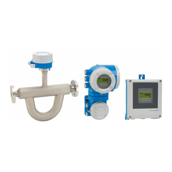
Product description Proline Promass Q 500 PROFIBUS PA Product description The measuring system consists of a transmitter and a sensor. The transmitter and sensor are mounted in physically separate locations. They are interconnected by one connecting cable(s). Product design Two versions of the transmitter are available. - Page 15 Proline Promass Q 500 PROFIBUS PA Product description 3.1.2 Proline 500 Signal transmission: analog Order code for "Integrated ISEM electronics", option B "Transmitter" For use in applications required to meet special requirements due to ambient or operating conditions. As the electronics are located in the transmitter, the device is ideal in the event of: •...
-
Page 16: Incoming Acceptance And Product
A0029318 • If one of the conditions is not satisfied, contact your Endress+Hauser Sales Center. • Depending on the device version, the CD-ROM might not be part of the delivery! The Technical Documentation is available via the Internet or via the Endress+Hauser Operations App, see the "Product identification"... -
Page 17: Product Identification
• Enter the serial number from the nameplates into the Endress+Hauser Operations App or scan the 2-D matrix code (QR code) on the nameplate with the Endress+Hauser Operations App: all the information for the measuring device is displayed. For an overview of the scope of the associated Technical Documentation, refer to the following: •... - Page 18 Incoming acceptance and product identification Proline Promass Q 500 PROFIBUS PA Proline 500 3 4 5 Order code: Ser. no.: Ext. ord. cd.: Date: A0029192 4 Example of a transmitter nameplate Manufacturing location Name of the transmitter Order code Serial number (ser.
-
Page 19: Sensor Nameplate
Proline Promass Q 500 PROFIBUS PA Incoming acceptance and product identification 4.2.2 Sensor nameplate Order code: Ser. no.: Ext. ord. cd.: Date: A0029199 5 Example of a sensor nameplate Name of the sensor Manufacturing location Order code Serial number (ser. no.) Extended order code (Ext. -
Page 20: Symbols On Measuring Device
Incoming acceptance and product identification Proline Promass Q 500 PROFIBUS PA 4.2.3 Symbols on measuring device Symbol Meaning WARNING! This symbol alerts you to a dangerous situation. Failure to avoid this situation can result in serious or fatal injury. Reference to documentation Refers to the corresponding device documentation. -
Page 21: Storage And Transport
Proline Promass Q 500 PROFIBUS PA Storage and transport Storage and transport Storage conditions Observe the following notes for storage: • Store in the original packaging to ensure protection from shock. • Do not remove protective covers or protective caps installed on process connections. -
Page 22: Measuring Devices With Lifting Lugs
Installation Proline Promass Q 500 PROFIBUS PA 5.2.2 Measuring devices with lifting lugs CAUTION Special transportation instructions for devices with lifting lugs ‣ Only use the lifting lugs fitted on the device or flanges to transport the device. ‣ The device must always be secured at two lifting lugs at least. - Page 23 Proline Promass Q 500 PROFIBUS PA Installation To prevent measuring errors arising from accumulation of gas bubbles in the measuring tube, avoid the following mounting locations in the pipe: • Highest point of a pipeline. • Directly upstream of a free pipe outlet in a down pipe.
-
Page 24: Requirements From Environment And Process
Installation Proline Promass Q 500 PROFIBUS PA Orientation Recommendation Horizontal orientation, transmitter at bottom Exceptions: → 7, 24 A0015590 Horizontal orientation, transmitter at → 25 side A0015592 Applications with low process temperatures may decrease the ambient temperature. To maintain the minimum ambient temperature for the transmitter, this orientation is recommended. -
Page 25: Special Mounting Instructions
‣ If operating outdoors: Avoid direct sunlight, particularly in warm climatic regions. You can order a weather protection cover from Endress+Hauser : → 241 Vibrations The operational reliability of the measuring system is not affected by plant vibrations. 6.1.3... - Page 26 Installation Proline Promass Q 500 PROFIBUS PA RUPTURE DISK A0030346 Rupture disk label Rupture disk with 1/2" NPT internal thread with 1" width across flat Transport protection Zero point adjustment All measuring devices are calibrated in accordance with state-of-the-art technology.
- Page 27 Proline Promass Q 500 PROFIBUS PA Installation 280 (11.0) 255 (10.0) 146 (5.75) 134 (5.3) 12 (0.47) 30 (1.18) A0029553 9 Weather protection cover for Proline 500 Cover locking: Proline 500 NOTICE Order code for "Housing", option L "Cast, stainless": The covers of the transmitter housing are provided with a borehole to lock the cover.
-
Page 28: Mounting The Measuring Device
Installation Proline Promass Q 500 PROFIBUS PA Pitch angle Roll angle +90° 0° α β 0° -90° +/-180° A0032309 A0032310 The adjustable pitch angle is the blue marked area of The adjustable roll angle is the blue marked area of angle α. -
Page 29: Mounting The Transmitter Housing: Proline 500 - Digital
Proline Promass Q 500 PROFIBUS PA Installation 2. Install the measuring device or turn the transmitter housing so that the cable entries do not point upwards. A0029263 6.2.4 Mounting the transmitter housing: Proline 500 – digital CAUTION Ambient temperature too high! Danger of electronics overheating and housing deformation. -
Page 30: Mounting The Transmitter Housing: Proline 500
Installation Proline Promass Q 500 PROFIBUS PA Wall mounting 17 (0.67) 14 (0.55) 5.8 (0.23) 5.8 (0.23) 149 (5.85) A0029054 11 Engineering unit mm (in) 1. Drill the holes. 2. Insert wall plugs into the drilled holes. 3. Screw in the securing screws slightly at first. - Page 31 Proline Promass Q 500 PROFIBUS PA Installation Wall mounting 18 (0.71) 10 (0.39) 20 (0.79) 100 (3.94) A0029068 12 Engineering unit mm (in) 1. Drill the holes. 2. Insert wall plugs into the drilled holes. 3. Screw in the securing screws slightly at first.
-
Page 32: Turning The Transmitter Housing: Proline 500
Installation Proline Promass Q 500 PROFIBUS PA Post mounting WARNING Order code for "Transmitter housing", option L "Cast, stainless": cast transmitters are very heavy. They are unstable if they are not mounted on a secure, fixed post. ‣ Only mount the transmitter on a secure, fixed post on a stable surface. -
Page 33: Turning The Display Module: Proline 500
Proline Promass Q 500 PROFIBUS PA Installation 6.2.7 Turning the display module: Proline 500 The display module can be turned to optimize display readability and operability. – – – 3 mm A0030035 1. Loosen the securing clamp of the connection compartment cover. -
Page 34: Electrical Connection
Electrical connection Proline Promass Q 500 PROFIBUS PA Electrical connection NOTICE The measuring device does not have an internal circuit breaker. ‣ For this reason, assign the measuring device a switch or power-circuit breaker so that the power supply line can be easily disconnected from the mains. - Page 35 Proline Promass Q 500 PROFIBUS PA Electrical connection Relay output Standard installation cable is sufficient. Current input 0/4 to 20 mA Standard installation cable is sufficient. Status input Standard installation cable is sufficient. Cable diameter • Cable glands supplied: M20 × 1.5 with cable ⌀ 6 to 12 mm (0.24 to 0.47 in) •...
- Page 36 Electrical connection Proline Promass Q 500 PROFIBUS PA Standard cable 4, 6, 8 cores (2, 3, 4 pairs); pair-stranded with common shield Shielding Tin-plated copper-braid, optical cover ≥ 85 % Capacitance C Maximum 760 nF IIC, maximum 4.2 µF IIB Inductance L Maximum 26 µH IIC, maximum 104 µH IIB...
-
Page 37: Terminal Assignment
Proline Promass Q 500 PROFIBUS PA Electrical connection Operating temperature When mounted in a fixed position: –50 to +105 °C (–58 to +221 °F); when cable can move freely: –25 to +105 °C (–13 to +221 °F) Available cable length Fixed: 20 m (65 ft);... -
Page 38: Pin Assignment Of Device Plug
Electrical connection Proline Promass Q 500 PROFIBUS PA Order code for "Input; output 1", option GA "PROFIBUS PA" Order code for Cable entry Cable entry "Electrical connection" L, N, P, U Plug M12 × 1 – 7.1.5 Pin assignment of device plug... -
Page 39: Connecting The Measuring Device: Proline 500 - Digital
Proline Promass Q 500 PROFIBUS PA Electrical connection Connecting the measuring device: Proline 500 – digital NOTICE Limitation of electrical safety due to incorrect connection! ‣ Have electrical connection work carried out by correspondingly trained specialists only. ‣ Observe applicable federal/national installation codes and regulations. - Page 40 Electrical connection Proline Promass Q 500 PROFIBUS PA Connecting the sensor connection housing via terminals For the device version with the order code for "Sensor connection housing": • Option A "Aluminum coated" • Option L "Cast, stainless" 10 (0.4) 3 mm...
- Page 41 Proline Promass Q 500 PROFIBUS PA Electrical connection Connecting the sensor connection housing via terminals For the device version with the order code for "Sensor connection housing": Option B "Stainless" 10 (0.4) 8 mm 22 mm 24 mm A0029613 1. Release the securing screw of the housing cover.
- Page 42 Electrical connection Proline Promass Q 500 PROFIBUS PA Connecting the sensor connection housing via the connector For the device version with the order code for "Sensor connection housing": Option C "Ultra-compact hygienic, stainless" A0029615 1. Connect the protective ground. 2. Connect the connector.
- Page 43 Proline Promass Q 500 PROFIBUS PA Electrical connection Connecting the connecting cable to the transmitter TX 20 TX 20 10 (0.4) 22 mm 24 mm A0029597 1. Loosen the 4 fixing screws on the housing cover. 2. Open the housing cover.
-
Page 44: Connecting The Signal Cable And The Supply Voltage Cable
Electrical connection Proline Promass Q 500 PROFIBUS PA 7.2.2 Connecting the signal cable and the supply voltage cable A0028200 Cable entry for supply voltage Cable entry for cable or connection of device plug for signal transmission Cable entry for cable or connection of device plug for signal transmission... - Page 45 Proline Promass Q 500 PROFIBUS PA Electrical connection WARNING Housing degree of protection may be voided due to insufficient sealing of the housing. ‣ Screw in the screw without using any lubricant. WARNING Excessive tightening torque applied to the fixing screws! Risk of damaging the plastic transmitter.
-
Page 46: Connecting The Measuring Device: Proline 500
Electrical connection Proline Promass Q 500 PROFIBUS PA Connecting the measuring device: Proline 500 NOTICE Limitation of electrical safety due to incorrect connection! ‣ Have electrical connection work carried out by correspondingly trained specialists only. ‣ Observe applicable federal/national installation codes and regulations. - Page 47 Proline Promass Q 500 PROFIBUS PA Electrical connection Connecting the sensor connection housing via terminals For the device version with the order code for "Housing": Option L "Cast, stainless" 10 (0.4) 3 mm 22 mm 24 mm A0029612 1. Loosen the securing clamp of the housing cover.
- Page 48 Electrical connection Proline Promass Q 500 PROFIBUS PA Connecting the sensor connection housing via terminals For the device version with the order code for "Housing": Option B "Stainless" 10 (0.4) 8 mm 22 mm 24 mm A0029613 1. Release the securing screw of the housing cover.
- Page 49 Proline Promass Q 500 PROFIBUS PA Electrical connection Connecting the connecting cable to the transmitter 10 (0.4) 3 mm 22 mm 24 mm A0029592 1. Loosen the securing clamp of the connection compartment cover. 2. Unscrew the connection compartment cover.
-
Page 50: Connecting The Signal Cable And The Supply Voltage Cable
Electrical connection Proline Promass Q 500 PROFIBUS PA 7.3.2 Connecting the signal cable and the supply voltage cable A0026781 Cable entry for supply voltage Cable entry for signal transmission, input/output 1 and 2 Cable entry for input/output signal transmission; Optional: connection of external WLAN antenna or service plug –... - Page 51 Proline Promass Q 500 PROFIBUS PA Electrical connection 10 (0.4) mm (in) – A0029815 7. Push the cable through the cable entry . To ensure tight sealing, do not remove the sealing ring from the cable entry. 8. Strip the cable and cable ends. In the case of stranded cables, also fit ferrules.
-
Page 52: Ensure Potential Equalization
Electrical connection Proline Promass Q 500 PROFIBUS PA Removing a cable 3 (0.12) A0029598 15 Engineering unit mm (in) 1. To remove a cable from the terminal, use a flat-blade screwdriver to push the slot between the two terminal holes 2. -
Page 53: Special Connection Instructions
Proline Promass Q 500 PROFIBUS PA Electrical connection Special connection instructions 7.5.1 Connection examples PROFIBUS-PA A0028768 16 Connection example for PROFIBUS-PA Control system (e.g. PLC) PROFIBUS PA segment coupler Cable shield: the cable shield must be grounded at both ends to comply with EMC requirements; observe cable... - Page 54 Electrical connection Proline Promass Q 500 PROFIBUS PA 4...20 mA A0028759 18 Connection example for 4-20 mA current output (passive) Automation system with current input (e.g. PLC) Active barrier for power supply (e.g. RN221N) Analog display unit: observe maximum load...
- Page 55 Proline Promass Q 500 PROFIBUS PA Electrical connection Relay output A0028760 21 Connection example for relay output (passive) Automation system with relay input (e.g. PLC) Power supply Transmitter: Observe input values → 248 Current input A0028915 22...
-
Page 56: Hardware Settings
Electrical connection Proline Promass Q 500 PROFIBUS PA Hardware settings 7.6.1 Setting the device address The address must always be configured for a PROFIBUS DP/PA device. The valid address range is between 1 and 126. In a PROFIBUS DP/PA network, each address can only be assigned once. -
Page 57: Ensuring The Degree Of Protection
Proline Promass Q 500 PROFIBUS PA Electrical connection Proline 500 transmitter Hardware addressing not used A0029637 Set the desired device address using the DIP switches in the connection compartment. A0029633 To switch addressing from software addressing to hardware addressing: set the DIP switch to On. -
Page 58: Post-Connection Check
Electrical connection Proline Promass Q 500 PROFIBUS PA 5. To ensure that moisture does not enter the cable entry: Route the cable so that it loops down before the cable entry ("water trap"). A0029278 6. Insert dummy plugs into unused cable entries. -
Page 59: Operation Options
Proline Promass Q 500 PROFIBUS PA Operation options Operation options Overview of operation options A0029295 Local operation via display module Computer with Web browser (e.g. Internet Explorer) or with operating tool (e.g. FieldCare, DeviceCare, AMS Device Manager, SIMATIC PDM) Field Xpert SFX350 or SFX370... -
Page 60: Structure And Function Of The Operating Menu
Operation options Proline Promass Q 500 PROFIBUS PA Structure and function of the operating menu 8.2.1 Structure of the operating menu For an overview of the operating menu for experts: "Description of Device Parameters" document supplied with the device→ 271... -
Page 61: Operating Philosophy
Proline Promass Q 500 PROFIBUS PA Operation options 8.2.2 Operating philosophy The individual parts of the operating menu are assigned to certain user roles (operator, maintenance etc.). Each user role contains typical tasks within the device lifecycle. For custody transfer, once the device has been put into circulation or sealed, its operation is restricted. -
Page 62: Access To The Operating Menu Via The Local Display
Operation options Proline Promass Q 500 PROFIBUS PA Menu/parameter User role and tasks Content/meaning Expert function-oriented Tasks that require detailed Contains all the parameters of the device and makes it possible to access these knowledge of the function of the parameters directly using an access code. - Page 63 Proline Promass Q 500 PROFIBUS PA Operation options Status area The following symbols appear in the status area of the operational display at the top right: • Status signals→ 166 – F: Failure – C: Function check – S: Out of specification –...
-
Page 64: Navigation View
Operation options Proline Promass Q 500 PROFIBUS PA 8.3.2 Navigation view In the submenu In the wizard /../Operation 0091-1 /../Select medium Access stat.disp Select medium Operator Liquid Locking status Display A0013993-EN A0013995-EN Navigation view Navigation path to current position Status area Display area for navigation Operating elements →... - Page 65 Proline Promass Q 500 PROFIBUS PA Operation options Display area Menus Symbol Meaning Operation Appears: • In the menu next to the "Operation" selection • At the left in the navigation path in the Operation menu Setup Appears: • In the menu next to the "Setup" selection •...
-
Page 66: Editing View
Operation options Proline Promass Q 500 PROFIBUS PA 8.3.3 Editing view Numeric editor Text editor User ABC_ DEFG HIJK LMNO PQRS TUVW A0013999 A0013941 Editing view Display area of the entered values Input mask Operating elements → 67 Input mask... -
Page 67: Operating Elements
Proline Promass Q 500 PROFIBUS PA Operation options Selection of letters from a to z. abc _ … Selection of special characters. "'^ _ … ~& Confirms selection. Switches to the selection of the correction tools. Exits the input without applying the changes. -
Page 68: Opening The Context Menu
Operation options Proline Promass Q 500 PROFIBUS PA Meaning Enter key For operational display • Pressing the key briefly opens the operating menu. • Pressing the key for 2 s opens the context menu. In a menu, submenu • Pressing the key briefly: –... - Page 69 Proline Promass Q 500 PROFIBUS PA Operation options 2. Press + simultaneously. The context menu is closed and the operational display appears. Calling up the menu via the context menu 1. Open the context menu. 2. Press to navigate to the desired menu.
-
Page 70: Navigating And Selecting From List
Operation options Proline Promass Q 500 PROFIBUS PA 8.3.6 Navigating and selecting from list Different operating elements are used to navigate through the operating menu. The navigation path is displayed on the left in the header. Icons are displayed in front of the individual menus. -
Page 71: Calling Up Help Text
Proline Promass Q 500 PROFIBUS PA Operation options The direct access code consists of a 4-digit number and the channel number, which identifies the channel of a process variable: e.g. 0914-1. In the navigation view, this appears on the right-hand side in the header of the selected parameter. -
Page 72: Changing The Parameters
Operation options Proline Promass Q 500 PROFIBUS PA 8.3.9 Changing the parameters For a description of the editing display - consisting of text editor and numeric editor - with symbols → 66, for a description of the operating elements → 67 Example: Changing the tag name in the "Tag description"... -
Page 73: User Roles And Related Access Authorization
Proline Promass Q 500 PROFIBUS PA Operation options Ent. access code Invalid or out of range input value Min:0 Max:9999 A0014049-EN 8.3.10 User roles and related access authorization The two user roles "Operator" and "Maintenance" have different write access to the parameters if the customer defines a user-specific access code. -
Page 74: Access To The Operating Menu Via The Web Browser
Operation options Proline Promass Q 500 PROFIBUS PA Local operation with touch control The keypad lock is switched on and off via the context menu. Switching on the keypad lock The keypad lock is switched on automatically: • Each time the device is restarted. - Page 75 Proline Promass Q 500 PROFIBUS PA Operation options Computer software Software Interface CDI-RJ45 WLAN Recommended operating • Microsoft Windows 7 or higher. systems • Mobile operating systems: – iOS – Android Microsoft Windows XP is supported. Web browsers supported •...
-
Page 76: Establishing A Connection
Operation options Proline Promass Q 500 PROFIBUS PA 8.4.3 Establishing a connection Via service interface (CDI-RJ45) Preparing the measuring device Proline 500 – digital 1. Loosen the 4 fixing screws on the housing cover. 2. Open the housing cover. 3. The location of the connection socket depends on the measuring device and the... - Page 77 Proline Promass Q 500 PROFIBUS PA Operation options NOTICE In principle, avoid simultaneous access to the measuring device via the service interface (CDI-RJ45) and the WLAN interface from the same mobile terminal. This could cause a network conflict. ‣ Only activate one service interface (CDI-RJ45 service interface or WLAN interface).
-
Page 78: Logging On
Operation options Proline Promass Q 500 PROFIBUS PA 2. Enter the IP address of the Web server in the address line of the Web browser: 192.168.1.212 The login page appears. 2 3 4 A0029417 Picture of device Device name... -
Page 79: User Interface
Proline Promass Q 500 PROFIBUS PA Operation options 8.4.5 User interface A0029418 Function row Operating language Navigation area Header The following information appears in the header: • Device tag • Device status with status signal → 169 • Current measured values... -
Page 80: Disabling The Web Server
Operation options Proline Promass Q 500 PROFIBUS PA Working area Depending on the selected function and the related submenus, various actions can be performed in this area: • Configuring parameters • Reading measured values • Calling up help text • Starting an upload/download 8.4.6... -
Page 81: Connecting The Operating Tool
Proline Promass Q 500 PROFIBUS PA Operation options 8.5.1 Connecting the operating tool Via PROFIBUS PA network This communication interface is available in device versions with PROFIBUS PA. A0028838 26 Options for remote operation via PROFIBUS PA network Automation system... - Page 82 Operation options Proline Promass Q 500 PROFIBUS PA Proline 500 transmitter A0027563 28 Connection via service interface (CDI-RJ45) Computer with Web browser (e.g. Microsoft Internet Explorer, Microsoft Edge) for accessing the integrated device Web server or with "FieldCare", "DeviceCare" operating tool with COM DTM "CDI Communication TCP/IP"...
-
Page 83: Fieldcare
FieldCare Function scope FDT-based plant asset management tool from Endress+Hauser. It can configure all smart field devices in a system and helps you manage them. By using the status information, it is also a simple but effective way of checking their status and condition. -
Page 84: Devicecare
Display area for current measured values Edit toolbar with additional functions such as save/restore, event list and create documentation Navigation area with operating menu structure Working area Range of action Status area 8.5.3 DeviceCare Function scope Tool to connect and configure Endress+Hauser field devices. Endress+Hauser... -
Page 85: Simatic Pdm
Proline Promass Q 500 PROFIBUS PA Operation options The fastest way to configure Endress+Hauser field devices is with the dedicated "DeviceCare" tool. Together with the device type managers (DTMs) it presents a convenient, comprehensive solution. For details, see Innovation Brochure IN01047S Source for device description files See information →... -
Page 86: System Integration
System integration Proline Promass Q 500 PROFIBUS PA System integration Overview of device description files 9.1.1 Current version data for the device Firmware version 01.00.zz • On the title page of the Operating instructions • On the transmitter nameplate • Firmware version Diagnostics →... -
Page 87: Manufacturer-Specific Gsd
Proline Promass Q 500 PROFIBUS PA System integration 9.2.1 Manufacturer-specific GSD This GSD guarantees the unrestricted functionality of the measuring device. Device-specific process parameters and functions are therefore available. Manufacturer-specific GSD ID number File name PROFIBUS PA 0x156D EH3x156D.gsd The fact that the manufacturer-specific GSD should be used is specified in the Ident number selector parameter by selecting the Manufacturer option. -
Page 88: Compatibility With Earlier Model
System integration Proline Promass Q 500 PROFIBUS PA Compatibility with earlier model If the device is replaced, the measuring device Promass 500 supports the compatibility of the cyclic data with previous models. It is not necessary to adjust the engineering parameters of the PROFIBUS network with the Promass 500 GSD file. -
Page 89: Using The Gsd Modules Of The Previous Model
Proline Promass Q 500 PROFIBUS PA System integration 2. Set the device address: The same device address that was set for the Promass 80 or Promass 83 PROFIBUS PA must be used. 3. Connect the measuring device Promass 500 PROFIBUS PA. - Page 90 System integration Proline Promass Q 500 PROFIBUS PA Control variable Function Support 0 → 8 Measuring mode: UNIDIRECTIONAL Cause: 0 → 9 Measuring mode: BIDIRECTIONAL The Profile Transducer Block Flow is no longer supported. To continue to use the functionality: Use the Totalizer operation mode parameter in the Totalizer function block.
-
Page 91: Cyclic Data Transmission
Proline Promass Q 500 PROFIBUS PA System integration Cyclic data transmission Cyclic data transmission when using the device master file (GSD). 9.5.1 Block model The block model shows which input and output data the measuring device makes available for cyclic data exchange. Cyclic data exchange takes place with a PROFIBUS master (Class 1), e.g. - Page 92 System integration Proline Promass Q 500 PROFIBUS PA AI module (Analog Input) Transmit an input variable from the measuring device to the PROFIBUS master (Class 1). The selected input variable, along with the status, is cyclically transmitted to the PROFIBUS Master (Class 1) via the AI module. The input variable is depicted in the first four bytes in the form of a floating point number as per the IEEE 754 standard.
- Page 93 Proline Promass Q 500 PROFIBUS PA System integration Function block Factory setting AI 7 AI 8 Data structure Input data of Analog Input Byte 1 Byte 2 Byte 3 Byte 4 Byte 5 Measured value: floating point number (IEEE 754)
- Page 94 System integration Proline Promass Q 500 PROFIBUS PA Selection: control totalizer CHANNEL Value SETTOT Control totalizer 33310 Totalize 33046 Resetting 33308 Adopt totalizer initial setting Factory setting Function block Factory setting: Value SETTOT (meaning) Totalizer 1, 2 and 3 0 (totalizing)
- Page 95 Proline Promass Q 500 PROFIBUS PA System integration Input data of TOTAL Byte 1 Byte 2 Byte 3 Byte 4 Byte 5 Measured value: floating point number (IEEE 754) Status AO module (Analog Output) Transmit a compensation value from the PROFIBUS master (Class 1) to the measuring device.
- Page 96 System integration Proline Promass Q 500 PROFIBUS PA Selection: device function The device function can be specified using the CHANNEL parameter. CHANNEL Device function Factory setting: Status (meaning) Empty pipe detection • 0 (device function not active) • 1 (device function active) Low flow cut off •...
- Page 97 Proline Promass Q 500 PROFIBUS PA System integration Data structure Output data of Discrete Output Byte 1 Byte 2 Discrete Status EMPTY_MODULE module This module is used to assign empty spaces arising from modules not being used in the slots .
-
Page 98: Commissioning
Commissioning Proline Promass Q 500 PROFIBUS PA Commissioning 10.1 Function check Before commissioning the measuring device: ‣ Make sure that the post-installation and post-connection checks have been performed. • "Post-installation check" checklist → 33 • "Post-connection check" checklist → 58 10.2... -
Page 99: Configuring The Measuring Device
Proline Promass Q 500 PROFIBUS PA Commissioning X X X X X X X 20.50 Main menu 0104-1 Display language English Operation Setup Display language 0104-1 English à Deutsch Español Français Display language 0104-1 à English Deutsch Español Français Hauptmenü... -
Page 100: Defining The Tag Name
Commissioning Proline Promass Q 500 PROFIBUS PA Navigation "Setup" menu Setup → 101 Device tag ‣ → 101 System units ‣ Medium selection → 104 ‣ Communication → 105 ‣ Analog inputs → 107 ‣... -
Page 101: Setting The System Units
Proline Promass Q 500 PROFIBUS PA Commissioning XXXXXXXXX A0029422 31 Header of the operational display with tag name Tag name Enter the tag name in the "FieldCare" operating tool → 84 Navigation "Setup" menu → Device tag Parameter overview with brief description... - Page 102 Commissioning Proline Promass Q 500 PROFIBUS PA Temperature unit → 103 Pressure unit → 103 Parameter overview with brief description Parameter Description Selection Factory setting Mass flow unit Select mass flow unit. Unit choose list Country-specific: • kg/h Result •...
- Page 103 Proline Promass Q 500 PROFIBUS PA Commissioning Parameter Description Selection Factory setting Temperature unit Select temperature unit. Unit choose list Country-specific: • °C Result • °F The selected unit applies for: • Electronic temperature parameter (6053) • Maximum value parameter (6051) •...
-
Page 104: Selecting And Setting The Medium
Commissioning Proline Promass Q 500 PROFIBUS PA 10.6.3 Selecting and setting the medium The Select medium wizard submenu contains parameters that must be configured in order to select and set the medium. Navigation "Setup" menu → Select medium ‣ Medium selection →... -
Page 105: Configuring Communication
Proline Promass Q 500 PROFIBUS PA Commissioning Parameter overview with brief description Parameter Prerequisite Description Selection / User Factory setting entry / User interface Select medium – Select medium type. • Liquid Liquid • Gas Select gas type The Gas option is selected in Select measured gas type. - Page 106 Commissioning Proline Promass Q 500 PROFIBUS PA Navigation "Setup" menu → Communication ‣ Communication → 106 Device address Parameter overview with brief description Parameter Description User entry Factory setting Device address Enter device address. 0 to 126 Endress+Hauser...
-
Page 107: Configuring The Analog Inputs
Proline Promass Q 500 PROFIBUS PA Commissioning 10.6.5 Configuring the analog inputs The Analog inputs submenu guides the user systematically to the individual Analog input 1 to n submenu. From here you get to the parameters of the individual analog input. -
Page 108: Displaying The I/O Configuration
Commissioning Proline Promass Q 500 PROFIBUS PA Parameter Prerequisite Description Selection / User Factory setting entry Fail safe type – Select the failure mode. • Fail safe value • Fallback value • Off Fail safe value In Fail safe type parameter, Specify the values to be output... -
Page 109: Configuring The Current Input
Proline Promass Q 500 PROFIBUS PA Commissioning 10.6.7 Configuring the current input The "Current input" wizard guides the user systematically through all the parameters that have to be set for configuring the current input. Navigation "Setup" menu → Current input ‣... -
Page 110: Configuring The Status Input
Commissioning Proline Promass Q 500 PROFIBUS PA 10.6.8 Configuring the status input The Status input submenu guides the user systematically through all the parameters that have to be set for configuring the status input. Navigation "Setup" menu → Status input ‣... - Page 111 Proline Promass Q 500 PROFIBUS PA Commissioning Signal mode → 111 Assign current output 1 to n → 111 Current span → 111 0/4 mA value → 112 20 mA value → 112 → 112...
- Page 112 Commissioning Proline Promass Q 500 PROFIBUS PA Parameter Prerequisite Description Selection / User Factory setting interface / User entry 0/4 mA value One of the following options is Enter 4 mA value. Signed floating-point Country-specific: selected in the Current span number • 0 kg/h parameter (→...
-
Page 113: 10.6.10 Configuring The Pulse/Frequency/Switch Output
Proline Promass Q 500 PROFIBUS PA Commissioning 10.6.10 Configuring the pulse/frequency/switch output The Pulse/frequency/switch output wizard guides you systematically through all the parameters that can be set for configuring the selected output type. Navigation "Setup" menu → Advanced setup → Pulse/frequency/switch output ‣... - Page 114 Commissioning Proline Promass Q 500 PROFIBUS PA Parameter overview with brief description Parameter Prerequisite Description Selection / User Factory setting interface / User entry Operating mode – Define the output as a pulse, • Pulse Pulse frequency or switch output. • Frequency • Switch Terminal number –...
- Page 115 Proline Promass Q 500 PROFIBUS PA Commissioning Configuring the frequency output Navigation "Setup" menu → Pulse/frequency/switch output ‣ Pulse/frequency/switch output 1 to n Operating mode → 115 Terminal number → 115 Signal mode → 115 → 116...
- Page 116 Commissioning Proline Promass Q 500 PROFIBUS PA Parameter Prerequisite Description Selection / User Factory setting interface / User entry Assign frequency output In the Operating mode Select process variable for • Off parameter (→ 113), the frequency output. • Mass flow Frequency option is selected.
- Page 117 Proline Promass Q 500 PROFIBUS PA Commissioning Parameter Prerequisite Description Selection / User Factory setting interface / User entry Maximum frequency value In the Operating mode Enter maximum frequency. 0.0 to 10 000.0 Hz 10 000.0 Hz parameter, the Frequency option is selected and one of...
- Page 118 Commissioning Proline Promass Q 500 PROFIBUS PA Parameter Prerequisite Description Selection / User Factory setting interface / User entry Measuring value at maximum In the Operating mode Enter measured value for Signed floating-point Depends on country frequency parameter, the Frequency maximum frequency. number and nominal...
- Page 119 Proline Promass Q 500 PROFIBUS PA Commissioning Parameter Prerequisite Description Selection / User Factory setting interface / User entry Failure frequency In the Operating mode Enter frequency output value 0.0 to 12 500.0 Hz 0.0 Hz parameter, the Frequency in alarm condition. option is selected and one of...
- Page 120 Commissioning Proline Promass Q 500 PROFIBUS PA Configuring the switch output Navigation "Setup" menu → Pulse/frequency/switch output ‣ Pulse/frequency/switch output 1 to n Operating mode → 120 Terminal number → 120 Signal mode → 120 → 121...
- Page 121 Proline Promass Q 500 PROFIBUS PA Commissioning Parameter Prerequisite Description Selection / User Factory setting interface / User entry Switch output function In the Operating mode Select function for switch • Off parameter the Switch option is output. • On selected. • Diagnostic behavior •...
-
Page 122: 10.6.11 Configuring The Relay Output
Commissioning Proline Promass Q 500 PROFIBUS PA Parameter Prerequisite Description Selection / User Factory setting interface / User entry Switch-off delay • The Switch option is Define delay for the switch-off 0.0 to 100.0 s 0.0 s selected in the Operating of status output. - Page 123 Proline Promass Q 500 PROFIBUS PA Commissioning Parameter overview with brief description Parameter Prerequisite Description Selection / User Factory setting interface / User entry Relay output function – Select the function for the • Closed Closed relay output. • Open • Diagnostic behavior • Limit •...
-
Page 124: 10.6.12 Configuring The Double Pulse Output
Commissioning Proline Promass Q 500 PROFIBUS PA Parameter Prerequisite Description Selection / User Factory setting interface / User entry Switch-on delay In the Relay output function Define delay for the switch-on 0.0 to 100.0 s 0.0 s parameter, the Limit option is of status output. -
Page 125: 10.6.13 Configuring The Local Display
Proline Promass Q 500 PROFIBUS PA Commissioning Parameter Description Selection / User interface / Factory setting User entry Assign pulse output 1 Select process variable for pulse output. • Off • Mass flow • Volume flow • Corrected volume flow • Target mass flow •... - Page 126 Commissioning Proline Promass Q 500 PROFIBUS PA Parameter overview with brief description Parameter Prerequisite Description Selection / User Factory setting entry Format display A local display is provided. Select how measured values • 1 value, max. size 1 value, max. size are shown on the display.
- Page 127 Proline Promass Q 500 PROFIBUS PA Commissioning Parameter Prerequisite Description Selection / User Factory setting entry 100% bargraph value 3 A selection was made in the Enter 100% value for bar Signed floating-point Value 3 display parameter. graph display. number Value 4 display A local display is provided.
-
Page 128: 10.6.14 Configuring The Low Flow Cut Off
Commissioning Proline Promass Q 500 PROFIBUS PA 10.6.14 Configuring the low flow cut off The Low flow cut off wizard systematically guides the user through all the parameters that must be set to configure low flow cut off. Navigation "Setup" menu → Low flow cut off ‣... -
Page 129: Configuring The Partial Filled Pipe
Proline Promass Q 500 PROFIBUS PA Commissioning 10.6.15 Configuring the partial filled pipe detection The Partial filled pipe detection wizard guides you systematically through all parameters that have to be set for configuring the monitoring of the pipe filling. Navigation "Setup"... -
Page 130: Advanced Settings
Commissioning Proline Promass Q 500 PROFIBUS PA 10.7 Advanced settings The Advanced setup submenu together with its submenus contains parameters for specific settings. Navigation to the "Advanced setup" submenu X X X X X X X 20.50 0104-1 Main menu... -
Page 131: Calculated Values
Proline Promass Q 500 PROFIBUS PA Commissioning ‣ WLAN settings → 138 ‣ Concentration ‣ Heartbeat setup ‣ Configuration backup → 139 ‣ Administration → 140 10.7.1 Calculated values The Calculated values submenu contains parameters for calculating the corrected volume flow. -
Page 132: Carrying Out A Sensor Adjustment
Commissioning Proline Promass Q 500 PROFIBUS PA Parameter Prerequisite Description Selection / User Factory setting interface / User entry Fixed reference density The Fixed reference density Enter fixed value for reference Positive floating- 1 kg/Nl option is selected in the density. point number Corrected volume flow calculation parameter parameter. -
Page 133: Configuring The Totalizer
Proline Promass Q 500 PROFIBUS PA Commissioning Zero point adjustment All measuring devices are calibrated in accordance with state-of-the-art technology. Calibration takes place under reference conditions → 253. Therefore, a zero point adjustment in the field is generally not required. - Page 134 Commissioning Proline Promass Q 500 PROFIBUS PA Parameter overview with brief description Parameter Description Selection Factory setting Assign process variable Select process variable for totalizer. • Mass flow Mass flow • Volume flow • Corrected volume flow • Target mass flow •...
-
Page 135: Carrying Out Additional Display Configurations
Proline Promass Q 500 PROFIBUS PA Commissioning 10.7.4 Carrying out additional display configurations In the Display submenu you can set all the parameters associated with the configuration of the local display. Navigation "Setup" menu → Advanced setup → Display ‣... - Page 136 Commissioning Proline Promass Q 500 PROFIBUS PA Parameter overview with brief description Parameter Prerequisite Description Selection / User Factory setting entry Format display A local display is provided. Select how measured values • 1 value, max. size 1 value, max. size are shown on the display.
- Page 137 Proline Promass Q 500 PROFIBUS PA Commissioning Parameter Prerequisite Description Selection / User Factory setting entry 0% bargraph value 3 A selection was made in the Enter 0% value for bar graph Signed floating-point Country-specific: Value 3 display parameter. display. number • 0 kg/h •...
-
Page 138: Wlan Configuration
Commissioning Proline Promass Q 500 PROFIBUS PA Parameter Prerequisite Description Selection / User Factory setting entry Separator A local display is provided. Select decimal separator for • . (point) . (point) displaying numerical values. • , (comma) Backlight One of the following Switch the local display •... -
Page 139: Configuration Management
Proline Promass Q 500 PROFIBUS PA Commissioning Parameter Prerequisite Description User entry / Factory setting Selection Assign SSID name – Select which name will be used • Device tag User-defined for SSID: device tag or user- • User-defined defined name. SSID name... -
Page 140: Using Parameters For Device Administration
Commissioning Proline Promass Q 500 PROFIBUS PA Parameter Description User interface / Selection Factory setting Backup state Shows the current status of data saving or • None None restoring. • Backup in progress • Restoring in progress • Delete in progress • Compare in progress •... - Page 141 Proline Promass Q 500 PROFIBUS PA Commissioning Using the parameter to define the access code Navigation "Setup" menu → Advanced setup → Administration → Define access code ‣ Define access code Define access code → 141 Confirm access code →...
-
Page 142: Simulation
Commissioning Proline Promass Q 500 PROFIBUS PA Parameter overview with brief description Parameter Description Selection Factory setting Device reset Reset the device configuration - either • Cancel Cancel entirely or in part - to a defined state. • To delivery settings •... - Page 143 Proline Promass Q 500 PROFIBUS PA Commissioning Device alarm simulation → 144 Diagnostic event category → 144 Diagnostic event simulation → 144 Parameter overview with brief description Parameter Prerequisite Description Selection / User Factory setting entry / User interface Assign simulation process variable –...
- Page 144 Commissioning Proline Promass Q 500 PROFIBUS PA Parameter Prerequisite Description Selection / User Factory setting entry / User interface Pulse output simulation 1 to n In the Operating mode Set and switch off the pulse • Off parameter, the Pulse option is output simulation.
-
Page 145: Protecting Settings From Unauthorized
Proline Promass Q 500 PROFIBUS PA Commissioning 10.9 Protecting settings from unauthorized access The following write protection options exist in order to protect the configuration of the measuring device from unintentional modification: • Protect access to parameters via access code → 145 •... -
Page 146: Write Protection Via Write Protection
Via Web browser, FieldCare, DeviceCare (via CDI-RJ45 service interface), fieldbus For a reset code, contact your Endress+Hauser service organization. 1. Navigate to the Reset access code parameter (→ 141). 2. Enter the reset code. - Page 147 Proline Promass Q 500 PROFIBUS PA Commissioning A0029675 1. Open the housing cover. 2. Remove the display module. 3. Fold open the terminal cover. 4. Setting the write protection (WP) switch on the main electronics module to the ON position enables hardware write protection.
- Page 148 Commissioning Proline Promass Q 500 PROFIBUS PA Proline 500 A0029630 Setting the write protection (WP) switch on the main electronics module to the ON position enables hardware write protection. In the Locking status parameter the Hardware locked option is displayed →...
-
Page 149: Operation
Proline Promass Q 500 PROFIBUS PA Operation Operation 11.1 Reading the device locking status Device active write protection: Locking status parameter Operation → Locking status Function scope of the "Locking status" parameter Options Description None The access status displayed in the Access status parameter applies → 73. Only appears on local display. -
Page 150: Measured Variables" Submenu
Operation Proline Promass Q 500 PROFIBUS PA 11.4.1 "Measured variables" submenu The Measured variables submenu contains all the parameters needed to display the current measured values for each process variable. Navigation "Diagnostics" menu → Measured values → Measured variables ‣... -
Page 151: Totalizer
Proline Promass Q 500 PROFIBUS PA Operation Parameter Prerequisite Description User interface Reference density – Displays the reference density currently Signed floating-point calculated. number Dependency The unit is taken from the Reference density unit parameter (→ 102). Temperature –... -
Page 152: Input Values" Submenu
Operation Proline Promass Q 500 PROFIBUS PA Parameter overview with brief description Parameter Prerequisite Description Selection / User Factory setting entry / User interface Assign process variable – Select process variable for • Mass flow Mass flow totalizer. • Volume flow • Corrected volume flow •... -
Page 153: Output Values
Proline Promass Q 500 PROFIBUS PA Operation Parameter overview with brief description Parameter Description User interface Measured values 1 to n Displays the current input value. Signed floating-point number Measured current 1 to n Displays the current value of the current input. - Page 154 Operation Proline Promass Q 500 PROFIBUS PA Navigation "Diagnostics" menu → Measured values → Output values → Value current output 1 to n ‣ Current output 1 to n → 154 Output current 1 to n → 154...
- Page 155 Proline Promass Q 500 PROFIBUS PA Operation Parameter overview with brief description Parameter Prerequisite Description User interface / User Factory setting entry Output frequency In the Operating mode Displays the value currently 0.0 to 12 500.0 Hz – parameter, the Frequency measured for the frequency option is selected.
-
Page 156: Adapting The Measuring Device To The Process
Operation Proline Promass Q 500 PROFIBUS PA Navigation "Diagnostics" menu → Measured values → Output values → Double pulse output ‣ Double pulse output → 156 Pulse output Parameter overview with brief description Parameter Description User interface Pulse output Shows the currently output pulse frequency. -
Page 157: Showing Data Logging
Proline Promass Q 500 PROFIBUS PA Operation Parameter overview with brief description Parameter Prerequisite Description Selection / User Factory setting entry Control Totalizer 1 to n – Control totalizer value. • Totalize Totalize • Reset + hold • Preset + hold Preset value 1 to n In the Assign process variable Specify start value for totalizer. - Page 158 Operation Proline Promass Q 500 PROFIBUS PA Navigation "Diagnostics" menu → Data logging ‣ Data logging → 159 Assign channel 1...4 → 159 Logging interval Clear logging data → 159 Data logging → 159 Logging delay →...
- Page 159 Proline Promass Q 500 PROFIBUS PA Operation Parameter overview with brief description Parameter Prerequisite Description Selection / User Factory setting entry / User interface Assign channel 1 to n The Extended HistoROM Assign process variable to • Off application package is logging channel. • Mass flow available.
-
Page 160: Diagnostics And Troubleshooting
Diagnostics and troubleshooting Proline Promass Q 500 PROFIBUS PA Diagnostics and troubleshooting 12.1 General troubleshooting For local display Error Possible causes Solution Local display dark and no output Supply voltage does not match the Apply the correct supply voltage . - Page 161 Proline Promass Q 500 PROFIBUS PA Diagnostics and troubleshooting For output signals Error Possible causes Solution Signal output outside the valid Main electronics module is Order spare part → 239. range defective. Device shows correct value on local Configuration error...
- Page 162 Diagnostics and troubleshooting Proline Promass Q 500 PROFIBUS PA Error Possible causes Solution Connection lost 1. Check cable connection and power supply. 2. Refresh the Web browser and restart if necessary. Content of Web browser Not using optimum version of Web 1.
-
Page 163: Diagnostic Information Via Light Emitting
Proline Promass Q 500 PROFIBUS PA Diagnostics and troubleshooting 12.2 Diagnostic information via light emitting diodes 12.2.1 Transmitter Proline 500 – digital Different LEDs in the transmitter provide information on the device status. A0029689 Supply voltage Device status Not used... -
Page 164: Sensor Connection Housing
Diagnostics and troubleshooting Proline Promass Q 500 PROFIBUS PA Proline 500 Different LEDs in the transmitter provide information on the device status. 1 2 3 4 5 A0029629 Supply voltage Device status Not used Communication Service interface (CDI) active Color... - Page 165 Proline Promass Q 500 PROFIBUS PA Diagnostics and troubleshooting Color Meaning Communication White Communication active Device status Error Flashing red Warning Supply voltage Green Supply voltage is ok Supply voltage is off or too low Endress+Hauser...
-
Page 166: Diagnostic Information On Local Display
Diagnostics and troubleshooting Proline Promass Q 500 PROFIBUS PA 12.3 Diagnostic information on local display 12.3.1 Diagnostic message Faults detected by the self-monitoring system of the measuring device are displayed as a diagnostic message in alternation with the operational display. - Page 167 Proline Promass Q 500 PROFIBUS PA Diagnostics and troubleshooting Diagnostic behavior Symbol Meaning Alarm • Measurement is interrupted. • Signal outputs and totalizers assume the defined alarm condition. • A diagnostic message is generated. Warning Measurement is resumed. The signal outputs and totalizers are not affected. A diagnostic message is generated.
-
Page 168: Calling Up Remedial Measures
Diagnostics and troubleshooting Proline Promass Q 500 PROFIBUS PA 12.3.2 Calling up remedial measures X X X X X X X X X X X X X X 20.50 S801 Supply voltage Menu Diagnostic list Diagnostics 1 S801 Supply voltage... -
Page 169: Calling Up Remedy Information
Proline Promass Q 500 PROFIBUS PA Diagnostics and troubleshooting A0031056 Status area with status signal Diagnostic information→ 167 Remedy information with Service ID In addition, diagnostic events which have occurred can be shown in the Diagnostics menu: • Via parameter •... -
Page 170: Calling Up Remedy Information
Diagnostics and troubleshooting Proline Promass Q 500 PROFIBUS PA Xxxxxx/…/…/ Device name: Xxxxxxx Mass flow: kg/h 12.34 Device tag: Xxxxxxx Volume flow: 12.34 m /h ³ Status signal: Function check (C) Xxxxxx Diagnostics 1: C485 Simu... Remedy information: Deactivate... Failure (F) -
Page 171: Adapting The Diagnostic Information
Proline Promass Q 500 PROFIBUS PA Diagnostics and troubleshooting The user is in the Diagnostics menu. 1. Call up the desired parameter. 2. On the right in the working area, mouse over the parameter. A tool tip with remedy information for the diagnostic event appears. - Page 172 Diagnostics and troubleshooting Proline Promass Q 500 PROFIBUS PA Coding Measuring value (hex) Byte 5 Quality Quality Substatus Limits A0021271-EN 34 Structure of the coding byte The content of the coding byte depends on the configured failsafe mode in the particular function block.
-
Page 173: Overview Of Diagnostic Information
Proline Promass Q 500 PROFIBUS PA Diagnostics and troubleshooting Diagnostic information pertaining to the electronics: diagnostic number 200 to 399 Measured value status (fixed assignment) Diagnostic behavior Device diagnosis Quality Coding Category (configurable) (fixed assignment) Quality Substatus (hex) (NE107) Alarm... -
Page 174: Diagnostic Of Sensor
Diagnostics and troubleshooting Proline Promass Q 500 PROFIBUS PA 12.7.1 Diagnostic of sensor Diagnostic information Remedy instructions Influenced measured variables Short text 022 Temperature sensor defective 1. Check or replace sensor electronic • Oscillation amplitude @1 module (ISEM) • Oscillation amplitude @1 Measured variable status 2. - Page 175 Proline Promass Q 500 PROFIBUS PA Diagnostics and troubleshooting Diagnostic information Remedy instructions Influenced measured variables Short text 046 Sensor limit exceeded 1. Inspect sensor • Oscillation amplitude @1 2. Check process condition • Oscillation amplitude @1 Measured variable status [from the factory] •...
- Page 176 Diagnostics and troubleshooting Proline Promass Q 500 PROFIBUS PA Diagnostic information Remedy instructions Influenced measured variables Short text 062 Sensor connection faulty 1. Check or replace sensor electronic • Oscillation amplitude @1 module (ISEM) • Oscillation amplitude @1 Measured variable status 2.
- Page 177 Proline Promass Q 500 PROFIBUS PA Diagnostics and troubleshooting Diagnostic information Remedy instructions Influenced measured variables Short text 063 Exciter current faulty 1. Check or replace sensor electronic • Oscillation amplitude @1 module (ISEM) • Oscillation amplitude @1 Measured variable status 2.
- Page 178 Diagnostics and troubleshooting Proline Promass Q 500 PROFIBUS PA Diagnostic information Remedy instructions Influenced measured variables Short text 082 Data storage 1. Check module connections • Oscillation amplitude @1 2. Contact service • Oscillation amplitude @1 Measured variable status • Signal asymmetry •...
- Page 179 Proline Promass Q 500 PROFIBUS PA Diagnostics and troubleshooting Diagnostic information Remedy instructions Influenced measured variables Short text 083 Memory content 1. Restart device • Oscillation amplitude @1 2. Restore HistoROM S-DAT backup • Oscillation amplitude @1 Measured variable status (' D evice reset' parameter) •...
- Page 180 Diagnostics and troubleshooting Proline Promass Q 500 PROFIBUS PA Diagnostic information Remedy instructions Influenced measured variables Short text 140 Sensor signal asymmetrical 1. Check or replace sensor electronic • Oscillation amplitude @1 module (ISEM) • Oscillation amplitude @1 Measured variable status [from the factory] 2.
- Page 181 Proline Promass Q 500 PROFIBUS PA Diagnostics and troubleshooting Diagnostic information Remedy instructions Influenced measured variables Short text 144 Measuring error too high 1. Check or change sensor • Oscillation amplitude @1 2. Check process conditions • Oscillation amplitude @1 Measured variable status [from the factory] •...
-
Page 182: Diagnostic Of Electronic
Diagnostics and troubleshooting Proline Promass Q 500 PROFIBUS PA 12.7.2 Diagnostic of electronic Diagnostic information Remedy instructions Influenced measured variables Short text 201 Device failure 1. Restart device • Oscillation amplitude @1 2. Contact service • Oscillation amplitude @1 Measured variable status •... - Page 183 Proline Promass Q 500 PROFIBUS PA Diagnostics and troubleshooting Diagnostic information Remedy instructions Influenced measured variables Short text 242 Software incompatible 1. Check software • Oscillation amplitude @1 2. Flash or change main electronics • Oscillation amplitude @1 Measured variable status module •...
- Page 184 Diagnostics and troubleshooting Proline Promass Q 500 PROFIBUS PA Diagnostic information Remedy instructions Influenced measured variables Short text 252 Modules incompatible 1. Check electronic modules • Oscillation amplitude @1 2. Change electronic modules • Oscillation amplitude @1 Measured variable status •...
- Page 185 Proline Promass Q 500 PROFIBUS PA Diagnostics and troubleshooting Diagnostic information Remedy instructions Influenced measured variables Short text 262 Sensor electronic connection faulty 1. Check or replace connection cable • Oscillation amplitude @1 between sensor electronic module • Oscillation amplitude @1...
- Page 186 Diagnostics and troubleshooting Proline Promass Q 500 PROFIBUS PA Diagnostic information Remedy instructions Influenced measured variables Short text 270 Main electronic failure Change main electronic module • Oscillation amplitude @1 • Oscillation amplitude @1 Measured variable status • Signal asymmetry •...
- Page 187 Proline Promass Q 500 PROFIBUS PA Diagnostics and troubleshooting Diagnostic information Remedy instructions Influenced measured variables Short text 271 Main electronic failure 1. Restart device • Oscillation amplitude @1 2. Change main electronic module • Oscillation amplitude @1 Measured variable status •...
- Page 188 Diagnostics and troubleshooting Proline Promass Q 500 PROFIBUS PA Diagnostic information Remedy instructions Influenced measured variables Short text 272 Main electronic failure 1. Restart device • Oscillation amplitude @1 2. Contact service • Oscillation amplitude @1 Measured variable status • Signal asymmetry •...
- Page 189 Proline Promass Q 500 PROFIBUS PA Diagnostics and troubleshooting Diagnostic information Remedy instructions Influenced measured variables Short text 273 Main electronic failure Change electronic • Oscillation amplitude @1 • Oscillation amplitude @1 Measured variable status • Signal asymmetry • Carrier mass flow Quality •...
- Page 190 Diagnostics and troubleshooting Proline Promass Q 500 PROFIBUS PA Diagnostic information Remedy instructions Influenced measured variables Short text 275 I/O module 1 to n defective Change I/O module • Oscillation amplitude @1 • Oscillation amplitude @1 Measured variable status • Signal asymmetry •...
- Page 191 Proline Promass Q 500 PROFIBUS PA Diagnostics and troubleshooting Diagnostic information Remedy instructions Influenced measured variables Short text 276 I/O module 1 to n faulty 1. Restart device • Oscillation amplitude @1 2. Change I/O module • Oscillation amplitude @1 Measured variable status •...
- Page 192 Diagnostics and troubleshooting Proline Promass Q 500 PROFIBUS PA Diagnostic information Remedy instructions Influenced measured variables Short text 276 I/O module 1 to n faulty 1. Restart device • Oscillation amplitude @1 2. Change I/O module • Oscillation amplitude @1 Measured variable status •...
- Page 193 Proline Promass Q 500 PROFIBUS PA Diagnostics and troubleshooting Diagnostic information Remedy instructions Influenced measured variables Short text 283 Memory content 1. Reset device • Oscillation amplitude @1 2. Contact service • Oscillation amplitude @1 Measured variable status • Signal asymmetry •...
- Page 194 Diagnostics and troubleshooting Proline Promass Q 500 PROFIBUS PA Diagnostic information Remedy instructions Influenced measured variables Short text 302 Device verification active Device verification active, please wait. • Oscillation amplitude @1 • Oscillation amplitude @1 Measured variable status • Signal asymmetry •...
- Page 195 Proline Promass Q 500 PROFIBUS PA Diagnostics and troubleshooting Diagnostic information Remedy instructions Influenced measured variables Short text 311 Electronic failure 1. Do not reset device • Oscillation amplitude @1 2. Contact service • Oscillation amplitude @1 Measured variable status •...
- Page 196 Diagnostics and troubleshooting Proline Promass Q 500 PROFIBUS PA Diagnostic information Remedy instructions Influenced measured variables Short text 332 Writing in embedded HistoROM failed Replace user interface board • Oscillation amplitude @1 Ex d/XP: replace transmitter • Oscillation amplitude @1 Measured variable status •...
- Page 197 Proline Promass Q 500 PROFIBUS PA Diagnostics and troubleshooting Diagnostic information Remedy instructions Influenced measured variables Short text 361 I/O module 1 to n faulty 1. Restart device • Oscillation amplitude @1 2. Check electronic modules • Oscillation amplitude @1 Measured variable status 3.
- Page 198 Diagnostics and troubleshooting Proline Promass Q 500 PROFIBUS PA Diagnostic information Remedy instructions Influenced measured variables Short text 372 Sensor electronic (ISEM) faulty 1. Restart device • Oscillation amplitude @1 2. Check if failure recurs • Oscillation amplitude @1 Measured variable status 3.
- Page 199 Proline Promass Q 500 PROFIBUS PA Diagnostics and troubleshooting Diagnostic information Remedy instructions Influenced measured variables Short text 373 Sensor electronic (ISEM) faulty 1. Transfer data or reset device • Oscillation amplitude @1 2. Contact service • Oscillation amplitude @1 Measured variable status •...
- Page 200 Diagnostics and troubleshooting Proline Promass Q 500 PROFIBUS PA Diagnostic information Remedy instructions Influenced measured variables Short text 374 Sensor electronic (ISEM) faulty 1. Restart device • Oscillation amplitude @1 2. Check if failure recurs • Oscillation amplitude @1 Measured variable status [from the factory] 3.
- Page 201 Proline Promass Q 500 PROFIBUS PA Diagnostics and troubleshooting Diagnostic information Remedy instructions Influenced measured variables Short text 375 I/O- 1 to n communication failed 1. Restart device • Oscillation amplitude @1 2. Check if failure recurs • Oscillation amplitude @1 Measured variable status 3.
- Page 202 Diagnostics and troubleshooting Proline Promass Q 500 PROFIBUS PA Diagnostic information Remedy instructions Influenced measured variables Short text 382 Data storage 1. Insert T-DAT • Oscillation amplitude @1 2. Replace T-DAT • Oscillation amplitude @1 Measured variable status • Signal asymmetry •...
- Page 203 Proline Promass Q 500 PROFIBUS PA Diagnostics and troubleshooting Diagnostic information Remedy instructions Influenced measured variables Short text 383 Memory content 1. Restart device • Oscillation amplitude @1 2. Delete T-DAT via ' R eset device' • Oscillation amplitude @1...
-
Page 204: Diagnostic Of Configuration
Diagnostics and troubleshooting Proline Promass Q 500 PROFIBUS PA Diagnostic information Remedy instructions Influenced measured variables Short text 387 Embedded HistoROM failed Contact service organization • Oscillation amplitude @1 • Oscillation amplitude @1 Measured variable status • Signal asymmetry • Carrier mass flow Quality •... - Page 205 Proline Promass Q 500 PROFIBUS PA Diagnostics and troubleshooting Diagnostic information Remedy instructions Influenced measured variables Short text 330 Flash file invalid 1. Update firmware of device • Oscillation amplitude @1 2. Restart device • Oscillation amplitude @1 Measured variable status •...
- Page 206 Diagnostics and troubleshooting Proline Promass Q 500 PROFIBUS PA Diagnostic information Remedy instructions Influenced measured variables Short text 331 Firmware update failed 1. Update firmware of device • Oscillation amplitude @1 2. Restart device • Oscillation amplitude @1 Measured variable status •...
- Page 207 Proline Promass Q 500 PROFIBUS PA Diagnostics and troubleshooting Diagnostic information Remedy instructions Influenced measured variables Short text 410 Data transfer 1. Check connection • Oscillation amplitude @1 2. Retry data transfer • Oscillation amplitude @1 Measured variable status • Signal asymmetry •...
- Page 208 Diagnostics and troubleshooting Proline Promass Q 500 PROFIBUS PA Diagnostic information Remedy instructions Influenced measured variables Short text 412 Processing download Download active, please wait • Oscillation amplitude @1 • Oscillation amplitude @1 Measured variable status • Signal asymmetry • Carrier mass flow...
- Page 209 Proline Promass Q 500 PROFIBUS PA Diagnostics and troubleshooting Diagnostic information Remedy instructions Influenced measured variables Short text 437 Configuration incompatible 1. Restart device • Oscillation amplitude @1 2. Contact service • Oscillation amplitude @1 Measured variable status • Signal asymmetry •...
- Page 210 Diagnostics and troubleshooting Proline Promass Q 500 PROFIBUS PA Diagnostic information Remedy instructions Influenced measured variables Short text 438 Dataset 1. Check data set file • Oscillation amplitude @1 2. Check device configuration • Oscillation amplitude @1 Measured variable status 3.
- Page 211 Proline Promass Q 500 PROFIBUS PA Diagnostics and troubleshooting Diagnostic information Remedy instructions Influenced measured variables Short text 442 Frequency output 1 to n 1. Check process – 2. Check frequency output settings Measured variable status [from the factory] Quality...
- Page 212 Diagnostics and troubleshooting Proline Promass Q 500 PROFIBUS PA Diagnostic information Remedy instructions Influenced measured variables Short text 453 Flow override Deactivate flow override • Oscillation amplitude @1 • Oscillation amplitude @1 Measured variable status • Signal asymmetry • Carrier mass flow...
- Page 213 Proline Promass Q 500 PROFIBUS PA Diagnostics and troubleshooting Diagnostic information Remedy instructions Influenced measured variables Short text 482 FB not Auto/Cas Set Block in AUTO mode – Measured variable status Quality Good Quality substatus Coding (hex) 0x80 to 0x83...
- Page 214 Diagnostics and troubleshooting Proline Promass Q 500 PROFIBUS PA Diagnostic information Remedy instructions Influenced measured variables Short text 485 Measured variable simulation Deactivate simulation • Oscillation amplitude @1 • Oscillation amplitude @1 Measured variable status • Signal asymmetry • Carrier mass flow...
- Page 215 Proline Promass Q 500 PROFIBUS PA Diagnostics and troubleshooting Diagnostic information Remedy instructions Influenced measured variables Short text 491 Current output 1 to n simulation Deactivate simulation – Measured variable status Quality Good Quality substatus Coding (hex) 0x80 to 0x83...
- Page 216 Diagnostics and troubleshooting Proline Promass Q 500 PROFIBUS PA Diagnostic information Remedy instructions Influenced measured variables Short text 495 Diagnostic event simulation Deactivate simulation – Measured variable status Quality Good Quality substatus Coding (hex) 0x80 to 0x83 Status signal Diagnostic behavior...
-
Page 217: Diagnostic Of Process
Proline Promass Q 500 PROFIBUS PA Diagnostics and troubleshooting Diagnostic information Remedy instructions Influenced measured variables Short text 537 Configuration 1. Check IP addresses in network – 2. Change IP address Measured variable status Quality Good Quality substatus Coding (hex) - Page 218 Diagnostics and troubleshooting Proline Promass Q 500 PROFIBUS PA Diagnostic information Remedy instructions Influenced measured variables Short text 830 Sensor temperature too high Reduce ambient temp. around the sensor • Oscillation amplitude @1 housing • Oscillation amplitude @1 Measured variable status [from the factory] •...
- Page 219 Proline Promass Q 500 PROFIBUS PA Diagnostics and troubleshooting Diagnostic information Remedy instructions Influenced measured variables Short text 831 Sensor temperature too low Increase ambient temp. around the sensor • Oscillation amplitude @1 housing • Oscillation amplitude @1 Measured variable status [from the factory] •...
- Page 220 Diagnostics and troubleshooting Proline Promass Q 500 PROFIBUS PA Diagnostic information Remedy instructions Influenced measured variables Short text 832 Electronic temperature too high Reduce ambient temperature • Oscillation amplitude @1 • Oscillation amplitude @1 Measured variable status [from the factory] •...
- Page 221 Proline Promass Q 500 PROFIBUS PA Diagnostics and troubleshooting Diagnostic information Remedy instructions Influenced measured variables Short text 833 Electronic temperature too low Increase ambient temperature • Oscillation amplitude @1 • Oscillation amplitude @1 Measured variable status [from the factory] •...
- Page 222 Diagnostics and troubleshooting Proline Promass Q 500 PROFIBUS PA Diagnostic information Remedy instructions Influenced measured variables Short text 834 Process temperature too high Reduce process temperature • Oscillation amplitude @1 • Oscillation amplitude @1 Measured variable status [from the factory] •...
- Page 223 Proline Promass Q 500 PROFIBUS PA Diagnostics and troubleshooting Diagnostic information Remedy instructions Influenced measured variables Short text 835 Process temperature too low Increase process temperature • Oscillation amplitude @1 • Oscillation amplitude @1 Measured variable status [from the factory] •...
- Page 224 Diagnostics and troubleshooting Proline Promass Q 500 PROFIBUS PA Diagnostic information Remedy instructions Influenced measured variables Short text 842 Process limit Low flow cut off active! • Oscillation amplitude @1 1. Check low flow cut off configuration • Oscillation amplitude @1 Measured variable status •...
- Page 225 Proline Promass Q 500 PROFIBUS PA Diagnostics and troubleshooting Diagnostic information Remedy instructions Influenced measured variables Short text 843 Process limit Check process conditions • Oscillation amplitude @1 • Oscillation amplitude @1 Measured variable status • Signal asymmetry • Carrier mass flow...
- Page 226 Diagnostics and troubleshooting Proline Promass Q 500 PROFIBUS PA Diagnostic information Remedy instructions Influenced measured variables Short text 882 Input signal 1. Check input configuration • Carrier mass flow 2. Check external device or process • Measured values @1 Measured variable status conditions •...
- Page 227 Proline Promass Q 500 PROFIBUS PA Diagnostics and troubleshooting Diagnostic information Remedy instructions Influenced measured variables Short text 912 Medium inhomogeneous 1. Check process cond. • Oscillation amplitude @1 2. Increase system pressure • Oscillation amplitude @1 Measured variable status [from the factory] •...
- Page 228 Diagnostics and troubleshooting Proline Promass Q 500 PROFIBUS PA Diagnostic information Remedy instructions Influenced measured variables Short text 913 Medium unsuitable 1. Check process conditions • Oscillation amplitude @1 2. Check electronic modules or sensor • Oscillation amplitude @1 Measured variable status [from the factory] •...
- Page 229 Proline Promass Q 500 PROFIBUS PA Diagnostics and troubleshooting Diagnostic information Remedy instructions Influenced measured variables Short text 944 Monitoring failed Check process conditions for Heartbeat • Oscillation amplitude @1 Monitoring • Oscillation amplitude @1 Measured variable status [from the factory] •...
-
Page 230: Pending Diagnostic Events
Diagnostics and troubleshooting Proline Promass Q 500 PROFIBUS PA Diagnostic information Remedy instructions Influenced measured variables Short text 948 Oscillation damping too high Check process conditions • Oscillation amplitude @1 • Oscillation amplitude @1 Measured variable status [from the factory] •... -
Page 231: Diagnostic List
Proline Promass Q 500 PROFIBUS PA Diagnostics and troubleshooting Navigation "Diagnostics" menu Diagnostics → 231 Actual diagnostics → 231 Previous diagnostics Operating time from restart → 231 Operating time → 231 Parameter overview with brief description... -
Page 232: 12.10 Event Logbook
Diagnostics and troubleshooting Proline Promass Q 500 PROFIBUS PA / ../Diagnose list Diagnostics F273 Main electronic Diagnostics 2 Diagnostics 3 A0014006-EN 35 Taking the example of the local display To call up the measures to rectify a diagnostic event: •... -
Page 233: 12.10.2 Filtering The Event Logbook
Proline Promass Q 500 PROFIBUS PA Diagnostics and troubleshooting 12.10.2 Filtering the event logbook Using the Filter options parameter you can define which category of event message is displayed in the Events list submenu. Navigation path Diagnostics → Event logbook → Filter options Filter categories •... -
Page 234: 12.11 Resetting The Measuring Device
Diagnostics and troubleshooting Proline Promass Q 500 PROFIBUS PA Info number Info name I1451 Monitoring on I1457 Measured error verification failed I1459 I/O module verification failed I1460 HBSI verification failed I1461 Sensor verification failed I1462 Sensor electronic module verific. failed... -
Page 235: 12.11.1 Function Scope Of The "Device Reset" Parameter
Proline Promass Q 500 PROFIBUS PA Diagnostics and troubleshooting 12.11.1 Function scope of the "Device reset" parameter Options Description Cancel No action is executed and the user exits the parameter. To delivery settings Every parameter for which a customer-specific default setting was ordered is reset to this customer-specific value. - Page 236 Diagnostics and troubleshooting Proline Promass Q 500 PROFIBUS PA Parameter overview with brief description Parameter Description User interface Factory setting Device tag Shows name of measuring point. Max. 32 characters, such as Promass300/500PA letters, numbers or special characters (e.g. @, %, /).
-
Page 237: 12.13 Firmware History
"Manufacturer' s information" document. The manufacturer' s information is available: • In the Download Area of the Endress+Hauser web site: www.endress.com → Downloads • Specify the following details: –... -
Page 238: Maintenance
13.2 Measuring and test equipment Endress+Hauser offers a wide variety of measuring and test equipment, such as W@M or device tests. Your Endress+Hauser Sales Center can provide detailed information on the services. -
Page 239: Repairs
• The measuring devices have a modular design. • Spare parts are grouped into logical kits with the associated Installation Instructions. • Repairs are carried out by Endress+Hauser Service or by appropriately trained customers. • Certified devices can only be converted to other certified devices by Endress+Hauser Service or at the factory. -
Page 240: Disposal
Repairs Proline Promass Q 500 PROFIBUS PA 14.5 Disposal 14.5.1 Removing the measuring device 1. Switch off the device. WARNING Danger to persons from process conditions. ‣ Beware of hazardous process conditions such as pressure in the measuring device, high temperatures or aggressive fluids. -
Page 241: Accessories
Various accessories, which can be ordered with the device or subsequently from Endress +Hauser, are available for the device. Detailed information on the order code in question is available from your local Endress+Hauser sales center or on the product page of the Endress+Hauser website: www.endress.com. -
Page 242: For The Sensor
Heating jacket Is used to stabilize the temperature of the fluids in the sensor. Water, water vapor and other non-corrosive liquids are permitted for use as fluids. If using oil as a heating medium, please consult with Endress+Hauser. 15.2 Service-specific accessories... - Page 243 Proline Promass Q 500 PROFIBUS PA Accessories Cerabar S The pressure transmitter for measuring the absolute and gauge pressure of gases, steam and liquids. It can be used to read in the operating pressure value. For details, see "Technical Information" TI00383P and Operating Instructions...
-
Page 244: Technical Data
Technical data Proline Promass Q 500 PROFIBUS PA Technical data 16.1 Application The measuring device is suitable for flow measurement of liquids and gases only. Depending on the version ordered, the measuring device can also measure potentially explosive, flammable, poisonous and oxidizing media. -
Page 245: Input
Proline Promass Q 500 PROFIBUS PA Technical data 16.3 Input Measured variable Direct measured variables • Mass flow • Density • Temperature Calculated measured variables • Volume flow • Corrected volume flow • Reference density Measuring range Measuring ranges for liquids... - Page 246 Input signal External measured values Various pressure transmitters and temperature measuring devices can be ordered from Endress+Hauser: see "Accessories" section → 242 It is recommended to read in external measured values to calculate the following measured variables for gases: •...
-
Page 247: Output
Proline Promass Q 500 PROFIBUS PA Technical data 16.4 Output Output signal PROFIBUS PA PROFIBUS PA In accordance with EN 50170 Volume 2, IEC 61158-2 (MBP), galvanically isolated Data transfer 31.25 KBit/s Current consumption 10 mA Permitted supply voltage 9 to 32 V... - Page 248 Technical data Proline Promass Q 500 PROFIBUS PA Assignable measured • Mass flow variables • Volume flow • Corrected volume flow • Density • Reference density • Temperature Frequency output Maximum input values DC 30 V, 250 mA (passive) Maximum output current 22.5 mA (active)
- Page 249 Proline Promass Q 500 PROFIBUS PA Technical data Maximum switching • DC 30 V, 0.1 A capacity (passive) • AC 30 V, 0.5 A Assignable functions • Off • On • Diagnostic behavior • Limit value – Mass flow – Volume flow –...
- Page 250 Technical data Proline Promass Q 500 PROFIBUS PA Pulse/frequency/switch output Pulse output Failure mode Choose from: • Actual value • No pulses Frequency output Failure mode Choose from: • Actual value • 0 Hz • Defined value (f 2 to 12 500 Hz)
- Page 251 Proline Promass Q 500 PROFIBUS PA Technical data Low flow cut off The switch points for low flow cut off are user-selectable. Galvanic isolation The outputs are galvanically isolated from one another and from earth (PE). Protocol-specific data Manufacturer ID...
-
Page 252: Power Supply
Technical data Proline Promass Q 500 PROFIBUS PA Input values Analog output 1 to 3 (fixed assignment) (from automation system to • Analog output 1: external pressure measuring device) • Analog output 2: external temperature • Analog output 3: external reference density Digital output 1 to 4: (fixed assignment) •... -
Page 253: Performance Characteristics
Proline Promass Q 500 PROFIBUS PA Technical data Order code for terminal voltage Frequency range "Power supply" DC 24 V ±20% – Option I AC100 to 240 V –15…+10% 50/60 Hz Power consumption Transmitter Max. 10 W (active power) Current consumption Transmitter •... - Page 254 Technical data Proline Promass Q 500 PROFIBUS PA Base accuracy Design fundamentals → 257 Mass flow and volume flow (liquids) ±0.05 % o.r. (PremiumCal; order code for "Calibration flow", option D, for mass flow) ±0.10 % o.r. Mass flow (gases) ±0.35 % o.r.
- Page 255 Proline Promass Q 500 PROFIBUS PA Technical data US units 1:10 1:20 1:50 1:100 1:500 [inch] [lb/min] [lb/min] [lb/min] [lb/min] [lb/min] [lb/min] 73.6 36.8 14.7 2 944 294.4 147.2 58.9 29.5 7 360 147.2 73.6 14.7 20 240 2 024 1 012 404.8...
- Page 256 Technical data Proline Promass Q 500 PROFIBUS PA o.f.s. = of full scale value When there is a difference between the temperature at zero point adjustment and the process temperature, the typical measured error of the sensor is DN 25 (1"): ±0.0001 % o.f.s./°C (±0.00005 % o.f.s./°F) DN 50, 80, 100 (2", 3", 4"): ±0.00015 % o.f.s./°C (±0.000075 % o.f.s./°F)
-
Page 257: Installation
Proline Promass Q 500 PROFIBUS PA Technical data Density [% o.r./bar] [% o.r./psi] [mm] [in] –0.0005 –0.00003 –0.0035 –0.00024 –0.0005 –0.00003 –0.0005 –0.00003 Design fundamentals o.r. = of reading, o.f.s. = of full scale value BaseAccu = base accuracy in % o.r., BaseRepeat = base repeatability in % o.r. -
Page 258: Environment
Technical data Proline Promass Q 500 PROFIBUS PA 16.8 Environment Ambient temperature → 24 range Temperature tables Observe the interdependencies between the permitted ambient and fluid temperatures when operating the device in hazardous areas. For detailed information on the temperature tables, see the separate document entitled "Safety Instructions"... - Page 259 Proline Promass Q 500 PROFIBUS PA Technical data A0031121 Ambient temperature Medium temperature Maximum permissible medium temperature at T = 60 °C (140 °F); higher medium temperatures require a A max reduction of the ambient temperature T (derating) Maximum permitted ambient temperature at the maximum specified medium temperature of the sensor...
- Page 260 Technical data Proline Promass Q 500 PROFIBUS PA testing. The corresponding type test declaration can be ordered with the device (order code for "Additional Approval", option LN "Type test containment"). Secondary containment Secondary containment burst pressure pressure rating (designed with a safety factor ≥...
-
Page 261: 16.10 Mechanical Construction
Proline Promass Q 500 PROFIBUS PA Technical data System pressure 16.10 Mechanical construction Design, dimensions For the dimensions and installation lengths of the device, see the "Technical Information" document, "Mechanical construction" section Weight All values (weight) refer to devices with EN/DIN PN 40 flanges. - Page 262 Technical data Proline Promass Q 500 PROFIBUS PA Window material Order code for "Transmitter housing": • Option A "Aluminum, coated": glass • Option D "Polycarbonate": plastic • Option L "Cast, stainless": glass Sensor connection housing Order code for "Sensor connection housing": •...
- Page 263 Proline Promass Q 500 PROFIBUS PA Technical data Cable entries and adapters Material • Adapter for cable entry with internal thread G ½" Stainless steel, 1.4404 (316L) • Adapter for cable entry with internal thread NPT ½" Only available for certain device versions: •...
-
Page 264: 16.11 Operability
Technical data Proline Promass Q 500 PROFIBUS PA Process connections Fixed flange connections: – EN 1092-1 (DIN 2501) flange – EN 1092-1 (DIN 2512N) flange – ASME B16.5 flange – JIS B2220 flange For information on the different materials used in the process connections → 263 Surface roughness All data relate to parts in contact with fluid. - Page 265 Proline Promass Q 500 PROFIBUS PA Technical data Display elements • 4-line, illuminated, graphic display • White background lighting; switches to red in event of device errors • Format for displaying measured variables and status variables can be individually configured •...
- Page 266 Technical data Proline Promass Q 500 PROFIBUS PA A device that has a WLAN interface (can be ordered as an option) is required for the WLAN connection: order code for "Display; operation", option G "4-line, illuminated; touch control + WLAN". The device acts as an Access Point and enables communication by computer or a mobile handheld terminal.
-
Page 267: 16.12 Certificates And Approvals
EU Directives. These are listed in the corresponding EU Declaration of Conformity along with the standards applied. Endress+Hauser confirms successful testing of the device by affixing to it the CE mark. C-Tick symbol The measuring system meets the EMC requirements of the "Australian Communications and Media Authority (ACMA)". - Page 268 Technical data Proline Promass Q 500 PROFIBUS PA Ex approval The devices are certified for use in hazardous areas and the relevant safety instructions are provided in the separate "Safety Instructions" (XA) document. Reference is made to this document on the nameplate.
-
Page 269: 16.13 Application Packages
The application packages can be ordered with the device or subsequently from Endress+Hauser. Detailed information on the order code in question is available from your local Endress+Hauser sales center or on the product page of the Endress+Hauser website: www.endress.com. -
Page 270: 16.14 Accessories
For an overview of the scope of the associated Technical Documentation, refer to the following: • The W@M Device Viewer : Enter the serial number from the nameplate (www.endress.com/deviceviewer) • The Endress+Hauser Operations App: Enter the serial number from the nameplate or scan the 2-D matrix code (QR code) on the nameplate. Endress+Hauser... - Page 271 Proline Promass Q 500 PROFIBUS PA Technical data Standard documentation Brief Operating Instructions Part 1 of 2: Sensor Measuring device Documentation code Proline Promass KA01212D Part 2 of 2: Transmitter Measuring device Documentation code Proline 500 KA01231D Technical Information Measuring device...
- Page 272 Technical data Proline Promass Q 500 PROFIBUS PA Installation Instructions Contents Documentation code Installation Instructions for spare part sets Overview of accessories available for order → 241 Endress+Hauser...
-
Page 273: Index
Discrete Output module ..... . . 96 Connection Display see Electrical connection see Local display Connection preparations ..... . 38 Endress+Hauser... - Page 274 Inlet runs ....... . . 24 Endress+Hauser services Input ........245 Maintenance .
- Page 275 Relay output 1 to n (Wizard) ....122 Transmitter ......17 Endress+Hauser...
- Page 276 Standards and guidelines ..... 269 Requirements for personnel ....10 Endress+Hauser...
- Page 277 For wizard ......65 W@M Device Viewer ....17, 239 Endress+Hauser...
- Page 278 Via write protection switch ....146 Write protection switch ..... . 146 Endress+Hauser...
- Page 280 www.addresses.endress.com...