
Related Manuals for Nortel MG 3200


Summary of Contents for Nortel MG 3200
- Page 1 Media Gateway 3200 Fast Track Installation Guide H.248 & SIP Version SN09 Document #: LTRT-73805...
- Page 3 Media Gateway 3200 Fast Track Installation Guide H.248 & SIP Version SN09 Document #: LTRT-73805 Published August-23-2005...
- Page 4 Notice This Fast Track Installation Guide describes the installation of the Nortel Media Gateway 3200 H.248 and SIP. Information contained in this document is believed to be accurate and reliable at the time of printing. However, due to ongoing product improvements and revisions, Nortel cannot guarantee the accuracy of printed material after the Date Published nor can it accept responsibility for errors or omissions.
-
Page 5: Table Of Contents
2.3 Mounting the MG 3200........................13 2.3.1 Mounting the MG 3200 on a Desktop ................13 2.3.2 Installing the MG 3200 in a 19-inch Rack ................. 13 2.4 Cabling the MG 3200 ........................15 2.4.1 Connecting the E1/T1 Trunk Interfaces ................16 2.4.2... - Page 6 Figure 2-1: MG 3200 Front View ........................11 Figure 2-2: 19-inch Rack & Desktop Accessories ................... 13 Figure 2-3: MG 3200 Front View with 19-inch Rack Mount Brackets ............. 14 Figure 2-4: MG 3200 Rear Panel Cabling (16 Trunks, Dual AC Power)............15 Figure 2-5: MG 3200 Rear Panel Cabling (8 Trunks, DC Power))..............
- Page 7 List of Tables Table 2-1: MG 3200 Front View Component Descriptions................11 Table 2-2: MG 3200 Rear Panel Cabling (16 Trunks, Dual AC Power) Component Descriptions ....15 Table 2-3: MG 3200 Rear Panel Cabling (8 Trunks, DC Power) Component Descriptions......15 Table 2-4: E1/T1 Connections on each 50-pin Telco Connector ..............
- Page 8 Related Documentation Document # Manual Name LTRT-727xx (e.g., LTRT-72703) MG 3200 H.248 User’s Manual LTRT-729xx MG 3200 H.248 Configuration Guide Note: Where the word “network” appears in this manual, it means LAN, WAN, etc., accessed via the gateway’s Ethernet interface.
-
Page 9: Quick Start
Media Gateway 3200 User’s Manuals. Figure 1-1: Required Steps to Install the Media Gateway 3200 Unpack the MG 3200 Refer to Section Refer to Section Mount the MG 3200... - Page 10 Media Gateway 3200 Reader’s Notes H.248/SIP Document #: LTRT-73805...
-
Page 11: Installing The Mg 3200
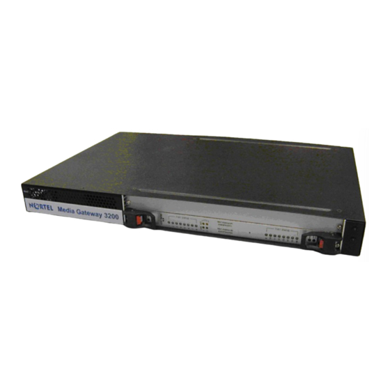
Fast Track Installation Guide 2. Installing the MG 3200 Installing the MG 3200 Figure 2-1 shows the front view of the MG 3200. For information on the MG 3200 LEDs refer to Section on page 33. Figure 2-1: MG 3200 Front View... -
Page 12: Unpacking
Cable the MG 3200 (refer to Section on page 15). After powering-up the MG 3200, the Ready and LAN LEDs on the front panel turn to green (after a self-testing period of about 3 minutes). Any malfunction changes the Ready LED to red (refer to... -
Page 13: Mounting The Mg 3200
This Fast Track Installation Guide. Figure 2-2: 19-inch Rack & Desktop Accessories Mounting the MG 3200 The MG 3200 can be mounted on a desktop, or installed in a standard 19-inch rack. Refer to Section on page for cabling the MG 3200. -
Page 14: Figure 2-3: Mg 3200 Front View With 19-Inch Rack Mount Brackets
(of your choosing) in the vertical tracks of the 19-inch rack. Use standard 19-inch rack bolts (not provided) to fasten the device to the frame of the rack. Nortel recommends using two additional (not supplied) rear mounting brackets to provide added support. -
Page 15: Cabling The Mg 3200
Fast Track Installation Guide 2. Installing the MG 3200 Cabling the MG 3200 The MG 3200 is available in many configurations, i.e., AC or DC, in the 16-trunk, 8-trunk, 4-trunk, 2-trunk or 1-trunk device. The 16-trunk dual AC (Figure 2-4) and the 8-trunk DC... -
Page 16: Connecting The E1/T1 Trunk Interfaces
2.4.1 Connecting the E1/T1 Trunk Interfaces Connect the MG 3200 E1/T1 Trunk Interfaces using either Telco or RJ-48 connectors: With 50-pin Telco connectors (16-trunk device), take these 3 steps: Attach the Trunk cable with a 50-pin male Telco connector to the 50-pin female Telco connector labeled “Trunks 1 8”... -
Page 17: Installing The Ethernet Connection
When initializing (connecting the MG 3200 to the network for the first time) use a standard Ethernet cable to connect the network interface on your computer to a port on a network hub/switch. Use a second standard Ethernet cable to connect the MG 3200 to another port on the same network hub/switch. -
Page 18: Connecting The Dc Power Supply
(for power source redundancy). 2.4.3.2 Connecting the DC Power Supply To connect the MG 3200 to a DC power supply use one of these two options: • DC Terminal block with a screw connection type. -
Page 19: Figure 2-10: Dc Terminal Block Crimp Connector
Fast Track Installation Guide 2. Installing the MG 3200 Figure 2-10: DC Terminal Block Crimp Connector 2 screws for connecting the crimp terminal block to the MG 3200 rear panel Version SN09 August 2005... -
Page 20: Configuring The Mg 3200
MAC and IP addresses (Table 3-1 shows the default IP addresses of the MG 3200). To assign an IP address to each of the MG 3200 modules use one of the following methods: •... -
Page 21: Assigning An Ip Address Using Bootp
Fast Track Installation Guide 3. Configuring the MG 3200 Click the Reset button and click OK in the prompt; The MG 3200 applies the changes and restarts. This takes approximately 3 minutes to complete. When the MG 3200 has finished restarting, the Ready and LAN LEDs on the front panel are lit green. -
Page 22: Restoring Networking Parameters To Their Initial State
Repeat steps 2 to 11 for the MG 3200 second module (if used). Figure 3-1: Client Configuration Screen with Blank Parameters Restoring Networking Parameters to their Initial State You can use the ‘Reset’ button to restore the MG 3200 networking parameters to their factory default values (described in Table 3-1) and to reset the username and password. -
Page 23: Accessing The Embedded Web Server
3.4.2 on page When you have completed the above relevant section you are then ready to start using the MG 3200. For information on how to fully configure the VoIP gateway, refer to the MG 3200 User’s Manuals. Tip: Once the gateway is configured correctly back up your settings by making a copy of the VoIP gateway configuration (ini file) and store it in a directory on your computer. -
Page 24: Configuring Basic H.248 Parameters
Setup’ screen is displayed, shown in Figure 3-3. Figure 3-3: MG 3200 H.248 Quick Setup Screen To configure basic H.248 parameters, take these 16 steps: If your network features a DNS server, in the fields ‘DNS Primary Server IP’ and ‘DNS Secondary Server IP’, enter the IP address of the primary and secondary DNS servers... - Page 25 Call Manager/Agent is configured with to identify your MG 3200. Click the Reset button and click OK in the prompt; The MG 3200 applies the changes and restarts. This takes approximately 3 minutes to complete. When the MG 3200 has finished restarting, the Ready and LAN LEDs on the front panel are lit green.
-
Page 26: Configuring Basic Sip Parameters
Enable the DMZ configuration on the residential router for the LAN port where the MG 3200 gateway is connected. Enter the public IP address for the MG 3200 in the ‘NAT IP Address’ field (in addition to the gateway’s local IP address). - Page 27 Select the coder (i.e., vocoder) that best suits your VoIP system requirements. The default coder is: G.7231 30 msec. To program the entire list of coders you want the MG 3200 to use, click the button on the left side of the ‘1 Coder’...
-
Page 28: Configuring The Trunk Settings
Media Gateway 3200 Note: The following Sections from here, up to the end of this Fast Track Guide, apply equally to H.248 and SIP. Configuring the Trunk Settings To configure the trunk settings, take these 13 steps: Access the Embedded Web Server (refer to Section on page 23). - Page 29 PSTN or PBX side is configured as ‘Network side’, and vice-versa. If you don’t know the MG 3200 ISDN termination side, choose ‘User Side’ and refer to the ‘Status & Diagnostics>Channel Status’ screen. If the D-channel alarm is indicated, choose ‘Network Side’.
- Page 30 Click the Save Configuration button in the middle of the screen; a confirmation message appears when the save is complete. For more detailed information on configuring the MG 3200 trunk settings, refer to the MG 3200 User’s Manual, document # LTRT-727xx.
-
Page 31: Changing The Mg 3200 Username And Password
4. Changing the MG 3200 Username and Password Changing the MG 3200 Username and Password To prevent unauthorized access to the MG 3200, it is recommended that you change the username and password (both are case-sensitive) that is used to access the Embedded Web Server. -
Page 32: Restoring And Backing Up The Mg 3200 Configuration
Media Gateway 3200 Restoring and Backing Up the MG 3200 Configuration The ‘Configuration File’ screen enables you to restore (load a new ini file to the gateway) or to back up (make a copy of the VoIP gateway ini file and store it in a directory on your computer) the current configuration the gateway is using. -
Page 33: Monitoring The Mg 3200
The MG 3200 provides several ways of monitoring the status of the gateway: • Monitoring the MG 3200 LEDs (refer to Section below). • Monitoring the MG 3200 trunks and B-channels via the Embedded Web Server (refer to Section on page 34). Monitoring the MG 3200 LEDs 6.1.1... -
Page 34: Monitoring The Mg 3200 Trunks And B-Channels
Blue The cPCI board was inserted successfully. During correct MG 3200 operation, the ACT LED is lit green, the FAIL LED is off. Changing of the FAIL LED to red indicates a failure. Monitoring the MG 3200 Trunks and B-channels To monitor the status of the trunks and B-channels: •... -
Page 35: Software Update
7. Software Update Software Update The ‘Software Update’ menu enables users to upgrade the MG 3200 software by loading a new cmp file along with the ini and a suite of auxiliary files, or to update the existing auxiliary files. -
Page 36: Figure 7-2: Load A Cmp File Screen
Start Software Upgrade button, the process must be followed through and completed with a MG 3200 reset at the end. If you click the Cancel button in any of the subsequent screens, the MG 3200 is automatically reset with the configuration that was previously burned in flash memory. -
Page 37: Figure 7-4: Load An Ini File Screen
Note that these are NOT the files you loaded in the previous Wizard steps. Click Reset; the MG 3200 resets, utilizing the new cmp and ini file you loaded up to now as well as utilizing the other configuration files. -
Page 38: Figure 7-5: Load A Cpt File Screen
Figure 7-5: Load a CPT File Screen Follow the same procedure you followed when loading the ini file (refer to Step 6). The same procedure applies to the ‘Load a VP file’ (not applicable to the MG 3200 gateway) screen and ‘Load a coefficient file’ screen. -
Page 39: Figure 7-7: 'End Process' Screen
Fast Track Installation Guide 7. Software Update Figure 7-7: ‘End Process’ Screen Click the End Process button; the ‘Quick Setup’ screen appears and the full Web application is reactivated. Version SN09 August 2005... -
Page 40: Updating The Auxiliary Files
Table 7-1: ini and Auxiliary Files Descriptions File Type Description Load the file to provision the MG 3200 parameters. The Embedded Web Server enables practically full device provisioning but customers may occasionally require new feature configuration parameters in which case this file is loaded. -
Page 41: Figure 7-8: Auxiliary Files Screen
Flash Memory’ screen is displayed. Note: Saving an auxiliary file to flash memory may disrupt traffic on the MG 3200. To avoid this, disable all traffic on the device before saving to flash memory. Click the Save Configuration button in the middle of the screen; a confirmation message appears when the save is complete. - Page 42 Media Gateway 3200 H.248/SIP Document #: LTRT-73804...