Table of Contents
Advertisement
Quick Links
MODEL G1023RL SERIES
10" TABLE SAW
WITH RIVING KNIFE
OWNER'S MANUAL
(For RL/RLW/RLX/RLWX/RLX5 models manufactured since 02/21)
G1023RLX/RLX5
G1023RLW/RLWX
G1023RL
177335
COPYRIGHT © MAY, 2010 BY GRIZZLY INDUSTRIAL, INC., REVISED FEBRUARY, 2021 (AI)
WARNING: NO PORTION OF THIS MANUAL MAY BE REPRODUCED IN ANY SHAPE
OR FORM WITHOUT THE WRITTEN APPROVAL OF GRIZZLY INDUSTRIAL, INC.
#BL12898 PRINTED IN TAIWAN
V5.02.21
Advertisement
Table of Contents

Related Manuals for Grizzly G1023RL Series


Summary of Contents for Grizzly G1023RL Series
- Page 1 G1023RLW/RLWX G1023RL 177335 COPYRIGHT © MAY, 2010 BY GRIZZLY INDUSTRIAL, INC., REVISED FEBRUARY, 2021 (AI) WARNING: NO PORTION OF THIS MANUAL MAY BE REPRODUCED IN ANY SHAPE OR FORM WITHOUT THE WRITTEN APPROVAL OF GRIZZLY INDUSTRIAL, INC. #BL12898 PRINTED IN TAIWAN...
- Page 2 This manual provides critical safety instructions on the proper setup, operation, maintenance, and service of this machine/tool. Save this document, refer to it often, and use it to instruct other operators. Failure to read, understand and follow the instructions in this manual may result in fire or serious personal injury—including amputation, electrocution, or death.
-
Page 3: Table Of Contents
Crosscut Sled..........55 Protecting Yourself from Kickback ....12 SECTION 6: AFTERMARKET ACCESSORIES SECTION 2: POWER SUPPLY ...... 13 FROM GRIZZLY ..........56 SECTION 3: SETUP ........15 SECTION 7: MAINTENANCE ......59 Needed for Setup ......... 15 Schedule ............59 Unpacking ............ -
Page 4: Introduction
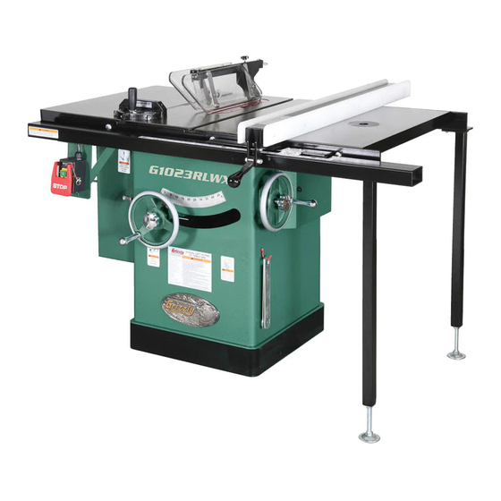
The G1023RL features two cast iron wings; the G1023RLW and G1023RLWX feature cast- iron router table extensions; the G1023RLX and G1023RLX5 feature heavy-duty extension tables with 53" rip capacity. Model G1023RL Series (Mfd. Since 02/21) -
Page 5: Identification
Keep hands out of the line of saw blade. d) Use a push-stick when required. e) Pay particular attention to instructions on reducing risk of kickback. f) Do not perform any operation freehand. g) Never reach around or over saw blade. G1023RLW/RLWX Model G1023RL Series (Mfd. Since 02/21) -
Page 6: Controls & Components
Figure 1. ON/OFF switch with disabling lock. K. Fence: Guides workpiece as it moves into blade and determines angle of cut. Figure 3. Table components. Model G1023RL Series (Mfd. Since 02/21) -
Page 7: Glossary Of Terms
The following is a list of common definitions, terms and phrases used throughout this manual as they relate to this table saw and woodworking in general. Become familiar with these terms for assembling, adjusting or operating this machine. Your safety is VERY important to us at Grizzly! Arbor: A metal shaft extending from the drive... -
Page 8: Machine Data Sheet
Machine Data Sheet Customer Service #: (570) 546-9663 · To Order Call: (800) 523-4777 · Fax #: (800) 438-5901 MODEL G1023RL SERIES 10" TABLE SAWS Model Number G1023RL G1023RLW G1023RLWX G1023RLX G1023RLX5 Product Dimensions Weight 471 lbs. 509 lbs. 522 lbs. - Page 9 Included Fence & Rails Additional Blade Information Included Blade Information 10" x 40T Riving Knife/Spreader Thickness 0.098"–0.102" Required Blade Body Thickness 0.086"–0.094" Required Blade Kerf Thickness 0.122"–0.129" Rim Speed at Maximum Blade 11,000 FPM Diameter Model G1023RL Series (Mfd. Since 02/21)
- Page 10 Optional Long Rails Compatible Mobile Base T28922 T28922 & T28347 Other Specifications Country of Origin Taiwan Warranty 1 Year Approximate Assembly & Setup Time 2 Hours Certified by a Nationally Recognized Testing Laboratory (NRTL) Model G1023RL Series (Mfd. Since 02/21)
-
Page 11: Section 1: Safety
Never operate under the influence of drugs or injury or blindness from flying particles. Everyday alcohol, when tired, or when distracted. eyeglasses are NOT approved safety glasses. Model G1023RL Series (Mfd. Since 02/21) - Page 12 Make sure they are properly installed, you experience difficulties performing the intend- undamaged, and working correctly BEFORE ed operation, stop using the machine! Contact our operating machine. Technical Support at (570) 546-9663. -10- Model G1023RL Series (Mfd. Since 02/21)
-
Page 13: Additional Safety For Table Saws
DO NOT attempt dado or rabbeting operations covered wood products, and some plastics. Never without first reading these sections in this manual. cut materials not intended for this saw. -11- Model G1023RL Series (Mfd. Since 02/21) -
Page 14: Preventing Kickback
Make multiple, shallow passes when per- forming a non-through cut. Making a deep • Use featherboards or anti-kickback devices non-through cut will greatly increase the to assist with feeding and prevent or slow chance of kickback. down kickback. -12- Model G1023RL Series (Mfd. Since 02/21) -
Page 15: Section 2: Power Supply
6-15 PLUG loading the machine during operation and make sure it is connected to a power supply circuit that meets the specified circuit requirements. Grounding Pin Figure 4. Typical 6-15 plug and receptacle. -13- Model G1023RL Series (Mfd. Since 02/21) - Page 16 If you ever notice that a cord or plug is damaged or worn, discon- nect it from power, and immediately replace it with a new one. -14- Model G1023RL Series (Mfd. Since 02/21)
-
Page 17: Section 3: Setup
Customer Service at (570) 546-9663 for advice. Save the containers and all packing materials for possible inspection by the carrier or its agent. Otherwise, filing a freight claim can be difficult. -15- Model G1023RL Series (Mfd. Since 02/21) -
Page 18: Hardware Recognition Chart
Hardware Recognition Chart -16- Model G1023RL Series (Mfd. Since 02/21) -
Page 19: Inventory
Hinge Pins (Motor Cover) ........2 Figure 8. G1023RL main components. Hex Wrenches 3, 5 ........1 Each Open-End Wrench 12 x 14mm ......1 Button Hd Cap Screw M5-.8 x 8 (Bracket) ..4 -17- Model G1023RL Series (Mfd. Since 02/21) - Page 20 A. Router Table Extension Wing ..... 1 Only the hardware needed to mount the fence B. Clamp Assemblies ........4 to your Grizzly saw is listed in this inventory and C. Table Insert 29mm ........1 D. Table Insert 60mm ........1 shown in Figure 9.
- Page 21 Hex Bolts ⁄ "-16 x 1 ⁄ " (Rtr Table/Rail) ....2 Grizzly saw is listed in this inventory and shown Lock Washers ⁄ " (Rtr Table/Rail) ..... 2 in Figure 12. To avoid confusion, we suggest Flat Washers ⁄...
-
Page 22: Cleanup
Figure 13. T23692 Orange Power Degreaser. Repeat Steps 2–3 as necessary until clean, then coat all unpainted surfaces with a quality metal protectant to prevent rust. -20- Model G1023RL Series (Mfd. Since 02/21) -
Page 23: Site Considerations
( G 1 0 2 3 R L W / G 1 0 2 3 R L W X o n l y ) = P o w e r C o n n e c t i o n Figure 14. Minimum working clearances. -21- Model G1023RL Series (Mfd. Since 02/21) -
Page 24: Assembly
Use a straightedge as a gauge and adjust extension wing up/down until it is flush with main table above each bolt, then completely tighten all bolts. Figure 15. Lifting straps supporting main table. -22- Model G1023RL Series (Mfd. Since 02/21) - Page 25 (see Figure 18). Figure 19. Installing switch. Figure 18. Masking tape location for adjusting the extension wing down. Note: After reinstalling wings, remove all excess masking tape with a razor blade. -23- Model G1023RL Series (Mfd. Since 02/21)
- Page 26 Figure 22. handwheel shaft, slide handwheel onto shaft, then tighten set screw on side of handwheel (see Figure 25). Set Screw Handle Handwheel Figure 25. Blade height handwheel installed. Figure 22. Motor cover installed. -24- Model G1023RL Series (Mfd. Since 02/21)
-
Page 27: Rails & Fence
(8) ⁄ "-16 x 1 ⁄ " hex bolts, (16) ⁄ " flat washers, and (8) ⁄ " hex nuts to secure extension table to rails, as shown in Figure 27. -25- Model G1023RL Series (Mfd. Since 02/21) -
Page 28: Saw Blade
Blade Guard Install the blade guard as instructed in "Installing Blade Guard & Spreader" on Page 34. -26- Model G1023RL Series (Mfd. Since 02/21) -
Page 29: Scale & Cursor
(4) amount of other open lines throughout the system. Explaining how to cal- culate these variables is beyond the scope of this manual. Consult an expert or purchase a good dust collection "how-to" book. -27- Model G1023RL Series (Mfd. Since 02/21) -
Page 30: Test Run
OFF . Blade Tilt Stop Accuracy (Page 65). Motor should run smoothly and without Miter Slot Parallel to Blade (Page 67). unusual problems or noises. Spreader/Riving Knife Alignment (Page 70). Turn machine OFF . -28- Model G1023RL Series (Mfd. Since 02/21) -
Page 31: Section 4: Operations
Read books/magazines or get formal training before beginning any proj- ects. Regardless of the content in this sec- tion, Grizzly Industrial will not be held liable for accidents caused by lack of training. -29- Model G1023RL Series (Mfd. Since 02/21) -
Page 32: Disabling & Locking Switch
Minor Warping: Slightly cupped workpieces can be safely supported with cupped side facing the table or fence; however, work- pieces supported on the bowed side will rock during the cut, which could cause kickback. -30- Model G1023RL Series (Mfd. Since 02/21) -
Page 33: Non-Through & Through Cuts
A dado blade smaller than 10" will require removal (3.1mm–3.3mm) of the riving knife, because the riving knife will be • Riving Knife Thickness: 0.98"–0.102" (2.5– higher than the blade. 2.6mm) • Blade Size Required for Riving Knife: 10" -31- Model G1023RL Series (Mfd. Since 02/21) -
Page 34: Blade Selection
Best for cutting across the grain • 60-80 teeth • Alternate top bevel tooth profile • Small hook angle and a shallow gullet Triple Chip Blade Alternate Bevel Figure 39. Laminate blade. Figure 37. Crosscutting blade. -32- Model G1023RL Series (Mfd. Since 02/21) -
Page 35: Blade Installation
Figure 41. Blade order of installation and teeth facing the correct direction. Raise arbor all the way up, and remove table insert and blade guard/riving knife, depend- Install blade guard and table insert. ing on what is installed. -33- Model G1023RL Series (Mfd. Since 02/21) -
Page 36: Blade Guard Assembly
-34- Model G1023RL Series (Mfd. Since 02/21) - Page 37 Close right access door. Check to make sure blade is 90° to table. Follow "Setting 90° Stop Bolt" instructions on Page 65. Swing one side of blade guard up and out of the way. -35- Model G1023RL Series (Mfd. Since 02/21)
- Page 38 Use good judgment! -36- Model G1023RL Series (Mfd. Since 02/21)
-
Page 39: Riving Knife
Guard Assembly on Page 34 for installation instructions. Top Distance Minimum 3mm Maximum 8mm Bottom Distance Minimum 3mm Maximum 8mm Figure 50. Allowable top and bottom distances between riving knife and blade. -37- Model G1023RL Series (Mfd. Since 02/21) -
Page 40: Ripping
Set up safety devices such as featherboards or other anti-kickback devices, making sure no safety devices are contacting blade. Keep blade guard installed and in down position. Failure to do this could result in serious personal injury or death. -38- Model G1023RL Series (Mfd. Since 02/21) -
Page 41: Crosscutting
Proceed to make cut in same manner as described in Crosscutting instructions. Turn saw OFF and allow blade to come to a complete stop before removing cutoff piece. Failure to follow this warning could result in severe lacerations or amputation. -39- Model G1023RL Series (Mfd. Since 02/21) -
Page 42: Blade Tilt/Bevel Cuts
Dado Blade the rotating blade, causing severe lacera- tions or amputation. Fence Workpiece Figure 55. Example of a dado being cut with a dado blade. -40- Model G1023RL Series (Mfd. Since 02/21) - Page 43 Cut 1 Fence Workpiece Cut 2 Fence Workpiece Cut 3 Fence Workpiece Finished Dado Cut Fence Workpiece Figure 56. Example of dado being cut with multiple light cuts, instead of one deep cut. -41- Model G1023RL Series (Mfd. Since 02/21)
- Page 44 Align blade to cut one side of dado, as shown in Figure 57. Figure 59. Additional single blade dado cuts. Blade Cut 1 Fence Workpiece Figure 57. First cut for a single-blade dado. -42- Model G1023RL Series (Mfd. Since 02/21)
-
Page 45: Rabbet Cutting
— If cut is satisfactory, repeat cut with is flat and straight, and make multiple light workpiece. cuts (rather than one deep cut) to achieve the desired cutting depth. -43- Model G1023RL Series (Mfd. Since 02/21) - Page 46 Figure 63. Example of second cut to create a standard blade. rabbet. — If workpiece is very tall, or is unstable when placed against fence, lay it flat on table and use a dado blade to perform rab- bet cut. -44- Model G1023RL Series (Mfd. Since 02/21)
-
Page 47: Resawing
Note: To determine the maximum resawing height for this table saw, find the maximum blade height, then double it and subtract ⁄ ". #8 x 2" ⁄ " Wood Screw ⁄ " Assembled Resaw Barrier Figure 64. Resaw barrier. -45- Model G1023RL Series (Mfd. Since 02/21) - Page 48 Countersink holes ⁄ " DISCONNECT MACHINE FROM POWER! deep so head of flat head cap screws sits slightly beneath face of auxiliary fence board. Remove standard table insert and blade guard assembly. -46- Model G1023RL Series (Mfd. Since 02/21)
- Page 49 12. When finished resawing, remove resaw bar- the desired depth of cut. Failure to follow rier and auxiliary fence, then re-install blade these warnings could result in serious per- guard/spreader or riving knife and standard sonal injury. table insert. -47- Model G1023RL Series (Mfd. Since 02/21)
-
Page 50: Section 5: Shop Made Safety Accessories
(the cuts are too far apart). will bend without breaking. Cut 30º angle at one end of board. Only Steps 1–3 are required to make a clamp-mounted featherboard. Refer to Page 50 for instructions on clamping. -48- Model G1023RL Series (Mfd. Since 02/21) - Page 51 Now, proceed to Mounting Featherboard in Drill ⁄ " hole in center of bar, then countersink Miter Slot on Page 50. bottom to fit ⁄ "-20 flat head screw. -49- Model G1023RL Series (Mfd. Since 02/21)
- Page 52 Note: The featherboard should be placed firmly enough against workpiece to keep it against fence but not so tight that it is difficult to feed workpiece. -50- Model G1023RL Series (Mfd. Since 02/21)
-
Page 53: Push Sticks
⁄ " Grid from the blade! Figure 76. Template for a basic shop-made push stick (not shown at actual size). -51- Model G1023RL Series (Mfd. Since 02/21) -
Page 54: Push Blocks
Lip for pushing workpiece ⁄ " Grid 9"−10" Minimum Length Figure 79. Template for a shop-made push block (shown at 50% of full size). -52- Model G1023RL Series (Mfd. Since 02/21) -
Page 55: Narrow-Rip Auxiliary Fence & Push Block
Attach handle to base with #8 x 1 ⁄ " wood screws, and attach lip to base with cyanoac- Length of Table rylate-type wood glue. Saw Rip Fence ⁄ " Figure 80. Auxiliary fence dimensions. -53- Model G1023RL Series (Mfd. Since 02/21) - Page 56 Place workpiece 1" behind blade and even- to a complete stop before removing cut-off ly against table and auxiliary fence (see piece. Failure to follow this warning could Figure 84). result in serious personal injury. -54- Model G1023RL Series (Mfd. Since 02/21)
-
Page 57: Outfeed & Support Tables
Crosscut Sled Support Outfeed Table Table Figure 87. Example of crosscut sled. Figure 86. Example of outfeed & support tables. -55- Model G1023RL Series (Mfd. Since 02/21) -
Page 58: Section 6: Aftermarket Accessories From Grizzly
Approximate shipping weight: 70 lbs. Figure 88. T28922 Bear Crawl "Cub" Mobile Base. Figure 90. T10113 Universal Overarm Blade Guard. www.grizzly.com 1-800-523-4777 order online at or call -56- Model G1023RL Series (Mfd. Since 02/21) - Page 59 Master Plate for a precision measurement, with no runout! Model G0710 Model G1163P Figure 94. Point-of-use dust collectors. Figure 92. Superbar™ and master plate. www.grizzly.com 1-800-523-4777 order online at or call -57- Model G1023RL Series (Mfd. Since 02/21)
- Page 60 No staggered steps or round bottoms like a wobble-dado leaves! Cuts in all directions - rip, cross-cut, miter, any depth. Figure 98. Hearing protection. Figure 96. Forrest Dado Blades. www.grizzly.com 1-800-523-4777 order online at or call -58- Model G1023RL Series (Mfd. Since 02/21)
-
Page 61: Section 7: Maintenance
SECTION 7: MAINTENANCE Cleaning Always disconnect power to the machine before Cleaning the Model G1023RL series table saw is performing maintenance. relatively easy. Vacuum excess wood chips and Failure to do this may sawdust, and wipe off the remaining dust with a result in serious person- dry cloth. -
Page 62: Lubrication
Front Trunnion film of grease. Slide Elevation Slides Rear Trunnion Slide Elevation Leadscrew Figure 100. Example of trunnion slides. Figure 102. Elevation leadscrew and elevation slides. -60- Model G1023RL Series (Mfd. Since 02/21) -
Page 63: Section 8: Service
11. Test all legs for power; repair/replace if at fault. 12. Centrifugal switch/contact points at fault. 12. Adjust centrifugal switch/clean contact points. Replace either if at fault. 13. Motor or motor bearings at fault. 13. Replace motor. -61- Model G1023RL Series (Mfd. Since 02/21) - Page 64 6. Miter slot not parallel with blade. 6. Adjust miter slot parallel with blade (Page 67). 7. Spreader/riving knife not correctly aligned 7. Adjust spreader/riving knife or spreader into with blade. alignment with blade (Page 70). -62- Model G1023RL Series (Mfd. Since 02/21)
- Page 65 1. Elevation slide gib out of adjustment. 1. Adjust elevation slide gib (Page 81). sloppy, inconsistent 2. Gas strut worn out. 2. Replace gas strut. from top to bottom, difficult to move, or it binds. -63- Model G1023RL Series (Mfd. Since 02/21)
- Page 66 (Page 65). Workpiece catches 1. Table insert not adjusted properly. 1. Adjust table/dado insert so it is perfectly flush with on table/dado insert table surface (Page 75). table opening during cutting operation. -64- Model G1023RL Series (Mfd. Since 02/21)
-
Page 67: Blade Tilt Stops
90° stop screw. Proceed to next tooth does not obstruct placement of square. step. Tilt blade to about 20°, so there is room for stop bolt to move. Blade 90° Square Table Figure 103. Checking blade at 90°. -65- Model G1023RL Series (Mfd. Since 02/21) - Page 68 — If blade is not 45° to table, you will need to adjust 45° stop screw. Proceed to next step. Figure 106. 90° stop bolt and jam nut (table removed for clarity). Tighten jam nut, then close motor cover. -66- Model G1023RL Series (Mfd. Since 02/21)
-
Page 69: Miter Slot To Blade Parallelism
Mark carbide tip with a marker where you made this measurement. Figure 109. Arbor height limit stops. The saw blade is sharp. Use extra care or wear gloves when handling the blade or working near it. -67- Model G1023RL Series (Mfd. Since 02/21) - Page 70 Do not forget to tighten table mounting bolts when finished. STEP B Table Mounting Locations Front Figure 112. Table mounting bolt holes (table top removed for clarity). Figure 114. Shim procedure diagram B. -68- Model G1023RL Series (Mfd. Since 02/21)
-
Page 71: Blade Alignment
3. Make sure blade does not contact table insert when raised or tilted. Recheck parallelism of blade to miter slot (refer to Page 67). Adjust as necessary until blade does not touch insert. -69- Model G1023RL Series (Mfd. Since 02/21) -
Page 72: Spreader Or Riving Knife Alignment
If spreader/riving knife does not lay evenly, proceed to Adjusting Bent Spreader/Riving Knife on Page 71. Top Alignment Bottom Alignment Figure 116. Checking top and bottom riving knife parallelism with blade. -70- Model G1023RL Series (Mfd. Since 02/21) - Page 73 — If this does not work, remove it to straight- Remove table insert. Loosen quick release lever shown in Figure — If you cannot straighten it properly, replace 119. Quick Release Lever Screws Figure 119. Quick release lever. -71- Model G1023RL Series (Mfd. Since 02/21)
-
Page 74: Fence Adjustments
Figure 120. Gap between fence and table approximately ⁄ " from to back. — If gap is uneven, if fence height is more than ⁄ ", or if fence touches table, then continue with Step 3. -72- Model G1023RL Series (Mfd. Since 02/21) - Page 75 — If miter slot is not parallel with blade, you must follow procedures described in Miter Space Slot to Blade Parallelism on Page 67. Between Fence & Blade Even Figure 124. Example of fence aligned parallel with miter slot. -73- Model G1023RL Series (Mfd. Since 02/21)
-
Page 76: Fence Scale Calibration
Measure width of freshly cut workpiece with a tape measure. Workpiece width should be exactly 12". If it is not, then adjust indicator window hairline to match width of workpiece. -74- Model G1023RL Series (Mfd. Since 02/21) -
Page 77: Miter Gauge Adjustments
— If insert is not flush with table, proceed to Step 3. Insert hex wrench through holes shown in Figure 127. Loosen screws to raise insert, or tighten screws to lower it. Repeat Steps 2–3 until insert is flush. -75- Model G1023RL Series (Mfd. Since 02/21) - Page 78 Loosen set screw on right front side of miter bar, adjust pointer to 0°, then tighten screw. Figure 131. Screws for adjusting miter bar in miter slot. Test fit miter bar in T-slot until it is snug. -76- Model G1023RL Series (Mfd. Since 02/21)
-
Page 79: Belt Tension & Replacement
Figure 133. Checking belt tension. — If there is more than ⁄ " deflection when flat belt is pushed with moderate pressure, loosen hex bolt, adjust motor downward, then tighten two hex bolts. Close motor cover. -77- Model G1023RL Series (Mfd. Since 02/21) - Page 80 Remove cap screws that secure mounting plate shown in Figure 135, then remove plate. Figure 137. Removing arbor lock nut. (Inset: arbor lock nut.) Mounting Cap Screws Plate Figure 135. Removing mounting plate. -78- Model G1023RL Series (Mfd. Since 02/21)
- Page 81 (see Figure 140). Bearing Rear Spacer Figure 142. Seating arbor into new bearing. 20. Using rubber hammer, seat arbor onto bearing (see Figure 142), then remove it from vise. Figure 140. Location of rear spacer. -79- Model G1023RL Series (Mfd. Since 02/21)
- Page 82 Figure 144. Re-installing arbor and belt. ing bolts. Re-check miter slot to blade parallelism and adjust as needed. 25. Tap arbor shaft into pulley, making sure shaft is straight. 26. Install rear spacer onto end of arbor. -80- Model G1023RL Series (Mfd. Since 02/21)
-
Page 83: Gib Adjustment
Gib Adjustment Wrench or Socket 12mm ........1 Hex Wrench 4mm ..........1 The Model G1023RL series has an elevation slide To adjust elevation slide gib: gib that can be adjusted to ensure smooth, con- sistent movement of the arbor. -
Page 84: Section 9: Wiring
Technical Support at (570) 546-9663. The photos and diagrams included in this section are best viewed in color. You can view these pages in color at www.grizzly.com. -82- Model G1023RL Series (Mfd. Since 02/21) -
Page 85: G1023Rl/Rlx/Rlw Electrical Components
G1023RL/RLX/RLW Electrical Components 3HP, 240V, 1-Ph Figure 146. On/off switch. Figure 148. Magnetic switch. Figure 147. Motor junction box. Figure 149. Start capacitor. READ ELECTRICAL SAFETY -83- Model G1023RL Series (Mfd. Since 02/21) ON PAGE 82! -
Page 86: G1023Rl/Rlx/Rlw Wiring
240V On/Off Switch (See Figure 139) 6-15 Plug (Included) L1/1 L2/3 L3/5 Ground MA-09 Magnetic 240V Switch T1/2 T2/4 T3/6 Assembly MPE-15 (See Figure 141) SDE RA-20 READ ELECTRICAL SAFETY -84- Model G1023RL Series (Mfd. Since 02/21) ON PAGE 82! -
Page 87: G1023Rlwx/Rlx5 Electrical Components
G1023RLWX/RLX5 Electrical Components 5HP, 240V, 1-Ph Figure 153. Start capacitor. Figure 150. Run capacitor. Figure 151. On/off switch. Figure 154. Magnetic switch. Figure 152. Motor junction box. READ ELECTRICAL SAFETY -85- Model G1023RL Series (Mfd. Since 02/21) ON PAGE 82! -
Page 88: G1023Rlwx/Rlx5 Wiring
L6-30 Plug (Included) Run Capacitor 60uf 300V On/Off Switch L1/1 L2/3 L3/5 NO13 Ground NC21 MA-18 NC22 240V Magnetic Switch T1/2 T2/4 T3/6 NO14 Assembly MPE-18 SDE RA-30 READ ELECTRICAL SAFETY -86- Model G1023RL Series (Mfd. Since 02/21) ON PAGE 82! -
Page 89: Section 10: Parts
26-1 6 (RLX5) 26-3V2 26-2 26-4 26-1 (G1023RLX5) 26-2 26-4 (G1023RLWX) 26-2 26-4V3 (G1023RL) 19-1 (G1023RLW) (G1023RLX) 24-1 19 (RLX5) 19V2 20-2 20-1 21-1 10-1 19V2 19 (RLX5) 27V2 (G1023RLWX) (G1023RL/RLW/RLX) (G1023RLX5) -8 7- Model G1023RL Series (Mfd. Since 02/21) - Page 90 REF PART # DESCRIPTION P1023RLX5026 MAG SWITCH ASSY MPE-18 26-1 P1023RLWX026-1 MAG SWITCH FRONT COVER 26-2 P1023RLWX026-2 MAG SWITCH BACK COVER 26-3 P1023RLWX026-3 CONTACTOR SDE MA-18 240V 26-4 P1023RLWX026-4 OL RELAY SDE RA-30 18-26A -88- Model G1023RL Series (Mfd. Since 02/21)
-
Page 91: G1023Rl (All) Arbor & Motor
30-4 30-5 30-9 30-7 30-6 30-8 52 (RLX5) 52V2 95 (RLX5) 95V2 43-1 115-1 43-1 113-1 96-1 54V2 35-1 54 (RLX5) 96V2 160 (RLX5) 94V2 84 85 94 (RLX5) 60 (RLX5) 60V2 43-1 -89- Model G1023RL Series (Mfd. Since 02/21) - Page 92 P1023RLWX030-9 CENTRIFUGAL SWITCH 3450RPM 30-8 P1023RL030-8 S CAPACITOR 600M 125V 1-3/4 X 3-3/8 30-10 P1023RLWX030-10 R CAPACITOR COVER 30-9 P1023RL030-9 CENTRIFUGAL SWITCH 3450RPM 30-12 P1023RLWX030-12 R CAPACITOR 60M 300V 1-3/4 X 3-3/8 V2.06.14 -90- Model G1023RL Series (Mfd. Since 02/21)
-
Page 93: G1023Rl (All) Blade Guard & Miter Gauge
FLANGE SCREW 10-24 X 1-1/4 P1023RL413 SET SCREW 10-24 X 5/8 P1023RL320 ARRESTING SPRING P1023RL414 ROLL PIN 1.5 X 13 P1023RL321 ROLL PIN 4 X 45 P1023RL415 MITER HINGE PIN P1023RL322 ROLL PIN 4 X 30 -91- Model G1023RL Series (Mfd. Since 02/21) -
Page 94: G1023Rl (All) Fence
MAGNIFIED CURSOR P1023RL544 MAGNET P1023RL517 HEX BOLT 1/4-20 X 1-3/4 P1023RL545 PHLP HD SCR 10-24 X 1/2 P1023RL520 HEX BOLT 3/8-16 X 1-3/4 P1023RL550 FENCE WARNING LABEL P1023RL522 PHLP HD SCR 10-24 X 3/8 -92- Model G1023RL Series (Mfd. Since 02/21) -
Page 95: G1023Rl/Rlw/Rlwx Fence Rails
P1023RL532 FLAT WASHER 3/8 P1023RL516 HEX BOLT 1/4-20 X 3/4 P1023RL533 FLAT WASHER 1/4 516-1 P1023RL516-1 FRONT RAIL 46-1/2" P1023RL534 HEX NUT 1/4-20 517-1V2 P1023RL517-1V2 REAR RAIL 54-1/2" V2.09.17 P1023RL551 RAIL WARNING LABEL -93- Model G1023RL Series (Mfd. Since 02/21) -
Page 96: G1023Rlx/Rlx5 Fence Rails
EXT. WOOD TABLE P1023RL518 HEX BOLT 3/8-16 X 1 P1023RLX551 RAIL WARNING LABEL P1023RLX519 HEX NUT 1/2-12 P1023RLX550 FLAT WASHER 1/4 P1023RL526 FLAT HD SCR 1/4-20 X 3/4 P1023RLX552 HEX BOLT 3/8-16 X 1-3/4 -94- Model G1023RL Series (Mfd. Since 02/21) -
Page 97: G1023Rlw/Rlwx, Router Table & Guard
LOCK WASHER #8 P1023RLW614 LOCK WASHER 3/8 620-10 P1023RLW620-10 HEX NUT 8-32 P1023RLW615 FLAT WASHER 3/8 620-11 P1023RLW620-11 PHLP HD SCR 10-24 X 2-1/2 P1023RLW616 HEX NUT 3/8-16 620-12 P1023RLW620-12 FLAT WASHER 1/4 -95- Model G1023RL Series (Mfd. Since 02/21) -
Page 98: Labels & Cosmetics
MUST maintain the original location and readability of the labels on the machine. If any label is removed or becomes unreadable, REPLACE that label before using the machine again. Contact Grizzly at (800) 523-4777 or www.grizzly.com to order new labels. -96-... -
Page 99: Warranty & Returns
WARRANTY & RETURNS Grizzly Industrial, Inc. warrants every product it sells for a period of 1 year to the original purchaser fro the date of purchase. This warranty does not apply to defects due directly or indirectly to misuse, abus negligence, accidents, repairs or alterations or lack of maintenance.