Table of Contents

Related Manuals for Grizzly G1023RL


Summary of Contents for Grizzly G1023RL
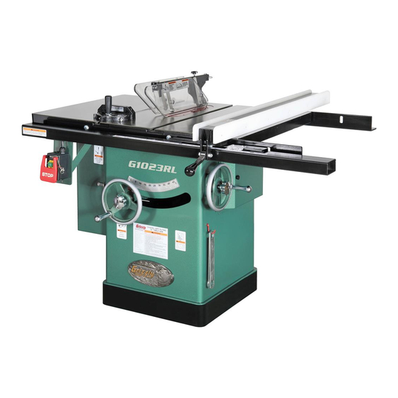
- Page 1 MODEL G1023RL SERIES 10" LEFT-TILT TABLE SAW WITH RIVING KNIFE OWNER'S MANUAL G1023RLX G1023RL G1023RLW/RLWX WARNING: NO PORTION OF THIS MANUAL MAY BE REPRODUCED IN ANY SHAPE OR FORM WITHOUT THE WRITTEN APPROVAL OF GRIZZLY INDUSTRIAL, INC.
-
Page 3: Table Of Contents
SECTION 4: OPERATIONS ... 26 Table of Contents SECTION ACCESSORIES ... 45 SECTION 6: AFTERMARKET ACCESSORIES FROM GRIZZLY ... 53 SECTION 7: MAINTENANCE ... 56 SECTION 8: SERVICE ... 58 SECTION 9: WIRING & ELECTRICAL ... 76 SECTION 10: PARTS ... 81 WARRANTY AND RETURNS ... -
Page 4: Introduction
INTRODUCTION Manual Accuracy Contact Info your machine may not exactly match the manual Machine Description www.grizzly.com... - Page 5 Use saw-blade guard and spreader for every operation for which it can be used, including all through sawing. c) Keep hands out of the line of saw blade. d) Use a push-stick when required. e) Pay particular attention to instructions on reducing risk of kickback.
-
Page 6: Machine Data Sheet
Machine Data Sheet MODEL G1023RL Series 10" LEFT-TILTING TABLE SAWS Model Number G1023RL G1023RLX G1023RLW G1023RLWX Motor Required Power Supply Circuit Speed Power Requirement Full Load Current Rating Power Connection Device Table Size (full assembly) Table Height Above Floor Overall Machine Size... -
Page 7: Section 1: Safety
SECTION 1: SAFETY For Your Own Safety, Read Instruction Manual Before Operating this Machine The purpose of safety symbols is to attract your attention to possible hazardous conditions. This manual uses a series of symbols and signal words intended to convey the level of impor- tance of the safety messages. - Page 8 DISCONNECTING POWER SUPPLY. APPROVED OPERATION. DANGEROUS ENVIRONMENTS. ONLY USE AS INTENDED. USE RECOMMENDED ACCESSORIES. CHILDREN & BYSTANDERS. REMOVE ADJUSTING TOOLS. SECURING WORKPIECE. FEED DIRECTION. FORCING MACHINERY. GUARDS & COVERS. NEVER STAND ON MACHINE. STABLE MACHINE. AWKWARD POSITIONS. UNATTENDED OPERATION. MAINTAIN WITH CARE. CHECK DAMAGED PARTS.
-
Page 9: Additional Safety For Table Saws
Additional Safety for Table Saws HAND POSITIONING. BLADE GUARD. RIVING KNIFE. KICKBACK. FEEDING WORKPIECE. FENCE. PUSH STICKS/BLOCKS. CUT-OFF PIECES. BLADE ADJUSTMENTS. CHANGING BLADES. DAMAGED SAW BLADES. DADO AND RABBET OPERATIONS. CUTTING CORRECT MATERIAL. -
Page 10: Preventing Kickback
Kickback is typically defined as the high-speed expulsion of stock from the table saw toward its opera- tor. In addition to the danger of the opera- tor or others in the area being struck by the flying stock, it is often the case that the operator’s hands are pulled into the... -
Page 11: Glossary Of Terms
Glossary of Terms Arbor: Bevel Edge Cut: Page 37 Blade Guard Assembly: Crosscut: Dado Blade: Dado Cut: Page 37 Featherboard: Page 45 Kerf: Kickback: on-Through Cut: Page 28 VERY Parallel: Perpendicular: Push Stick: Page 31 Page 49 Rabbet: Page 40 Page 36 Rip Cut: Riving Knife:... -
Page 12: Section 2: Power Supply
Circuit Requirements Nominal Voltage ... 220V/240V Cycle ...60 Hz Phase ... 1-Phase Circuit Rating (G1023RL/RL/RLW) ... 15 Amps Circuit Rating (G1023RLWX) ... 30 Amps... - Page 13 DO NOT connect to power until instructed later in this manual. G1023RL/RLW/RLX Connection Type & Grounding GROUNDED 6-15 RECEPTACLE 6-15 PLUG Figure 1. Min. Gauge (G1023RL/RL/RLW) ...14 AWG Maximum Length (Shorter is Better)...50 ft. G1023RLWX Connection Type & Grounding Figure Figure 2.
-
Page 14: Section 3: Setup
SECTION 3: SETUP This machine presents serious injury hazards to untrained users. Read through this entire manu- al to become familiar with the controls and opera- tions before starting the machine! Wear safety glasses dur- ing the entire setup pro- cess! This machine and its com- ponents are very heavy. - Page 15 Hardware Recognition Chart...
- Page 16 If you cannot find an item on this list, check the mounting location on the machine or the packaging materials. Sometimes parts are pre-installed for shipping, or they become hidden by packaging materials. Table Saw Unit Box Contents: (Figures 3–5) Hardware and Tools (Not Shown) Figure 3. Figure 4.
- Page 17 Fence & Rail Inventory G1023RL, G1023RLW, G1023RLWX Figure 6 Box Contents (Figure 6): Figure 6. Hardware and Tools (Not Shown): Router Table & Guard Inventory G1023RLW, G1023RLWX Box Contents (Figures 7 –8) Figure 7. Figure 8.
- Page 18 Hardware and Tools (Not Shown): Router Table Guard Fence & Rail Inventory G1023RLX Figure 9 Box Contents (Figure 9) Figure 9. Hardware and Tools (Not Shown):...
- Page 19 Cleanup Before cleaning, gather the following: H9692—Orange Power Cleaner & Degreaser Figure 10. Note: In a pinch, automotive degreasers, mineral ventative. Before using these products, though, test them on an inconspicuous area of your paint to make sure they will not damage it. Gasoline and petroleum products have low flash points and can explode...
-
Page 20: Site Considerations
Weight Load Machine Data Sheet Space Allocation See below for required space allocation. Children or untrained people may be seriously injured by this machine. Only install in an access restricted location. G1023RL/RLW/RLWX Physical Environment Electrical Installation Lighting Figure 11. G1023RLX... - Page 21 Assembly Model G1023RL Only after Model G1023RLW/RLWX/RLX Only: after To assemble your machine: Figure 12. Page 23 Figure 13 Figure 12 Figure 13 Get lifting help during the next step! The extension wings are heavy and can be difficult for one per- son to install.
- Page 22 Figure 14. Figure 15. Note: After reinstalling wings, remove all excess masking tape with a razor blade. Model G1023RL: 3–7 Model G1023RLW or G1023RLWX: Router Table & Legs Figure Model G1023RLX: Page 22. Figure 15 after Page 22 after Extension Table & Legs Figure 16 Figure 16.
- Page 23 Figure 17. Figure 20. Figure 18 Figure 21 Figure 18. Figure 21. Figure 22 Figure 19 Figure 22. Rails & Fence Figure 19. Figure 20...
- Page 24 Router Table & Legs Extension Table & Legs To install the Model G1023RLX extension table and legs: Figure 23 Figure 23. Figure 24 Figure 24. Figure 24 Figure 25 Figure 25.
-
Page 25: Saw Blade
Saw Blade Checking Fence Parallelism Blade Installation Page 30. Table Insert Page 67 To install the table insert: Blade Guard Figure 26 Page 31 Scale & Cursor Mounting Router Figure 26. Guard & Router Checking Fence Parallelism Blade Guard... -
Page 26: Dust Collection
Dust Collection DO NOT operate the table saw without an adequate dust collection system. This saw creates substantial amounts of wood dust while operating. Failure to use a dust collec- tion system can result in short and long-term respiratory illness. - Page 27 Test Run Troubleshooting Page 58 To test run the machine: Power Connection Figure 28 Figure 28. Recommended Page 24 Adjustments Adjustments that should be verified: SECTION 7: SERVICE Page 60 Page 62 Page 64...
-
Page 28: Section 4: Operations
"how to" books before beginning any projects. Regardless of the content in this section, Grizzly Industrial will not be held liable for accidents caused by lack of training. Basic Controls ON/OFF Switch:... -
Page 29: Operation Overview
Operation Overview To complete a typical operation, the operator does the following: Disabling & Locking Switch Figure 31. Children or untrained people can be killed or seriously injured by this machine. If machine is accessible to children or other people, always disable and lock the switch before leaving machine unattended! Place key in a well-hidden or secure location. -
Page 30: Stock Inspection
Non-Through & Through Cuts Non-Through Cuts Figure 33. " Through Cuts Figure Figure 34. Stock Inspection Before cutting, inspect all workpieces for the following: Material Type: Figure Foreign Objects: Large/Loose Knots: Wet or “Green” Stock: Excessive Warping: Minor Warping:... -
Page 31: Blade Requirements
Crosscut blade features: Blade Requirements Figure 36. Blade Selection Combination blade features: Ripping Blade Features: Figure 37. Figure 35. -
Page 32: Blade Installation
Blade Requirements Dado Blades Stacked Dado Blade (see below): Wobble Dado Blade: Figure 39. Blade Installation The saw blade is sharp. Use extra care and wear gloves when installing the blade. To install a new blade: Figure 40, Figure 40. -
Page 33: Blade Guard Assembly
Blade Guard Assembly Figure 41 Figure 41. Guard Spreader In order to work properly, the spreader cannot be bent or misaligned with the blade. If the spreader gets accidentally bent, take the time to straighten it or just replace it. Using a bent or misaligned spreader will increase the risk of kickback! Refer to Page 64 to check or adjust alignment if... - Page 34 Figure 43 Figure 43. Figure 44 Figure 44 insert removed for clarity Page 60 Figure 45 Figure 45. Removing Blade Guard & Spreader Step 1 " Page...
- Page 35 Anti-Kickback Pawls Figure 46 Disabling Pawls We do not recommend disabling the pawls during normal operations unless absolutely necessary. In most situations, disabling the pawls will increase your risk of serious per- sonal injury in the event of a kickback. The pawls are sharp and can lacerate fin- gers or hands.
-
Page 36: Riving Knife
Riving Knife Figure 48 Figure 48. Figure 49 Figure 49 To ensure that the riving knife works safe- ly, it MUST be aligned with and correctly adjusted to the blade. Refer to Page 64 to check or adjust the riving knife alignment. When to Use the Riving Knife When Not to Use the Riving Knife we strongly recommend... - Page 37 Page 8 Figure 50. Turn OFF the saw and allow the blade to come to a complete stop before removing the cut-off piece. Failure to follow this warn- ing could result in serious personal injury.
- Page 38 To make a crosscut using the miter gauge: Figure 51 Figure 51. Turn OFF the saw and allow the blade to come to a complete stop before removing the cut-off piece. Failure to follow this warn- ing could result in serious personal injury...
-
Page 39: Dado Cutting
Blade Tilt/Bevel Cuts Page 60 Figure 53 Figure 53 Dado Cutting Figure 54 Dado Blade Figure 54. Installing a Dado Blade Dado blades have a higher risk of kickback than normal blades because their larger size applies stronger forces to the workpiece. This risk increases relative to the depth and width of the cut. - Page 40 Cutting Dadoes with a Dado Blade Figure Dado Blade Cut 1 Cut 2 Cut 3 Finished Dado Cut Figure 55. To cut a dado with a dado blade: — Figure...
- Page 41 Cutting Dadoes with a Standard Blade Page 29 To use a standard saw blade to cut dadoes: Page 36 Figure 56 Blade Cut 1 Figure 56. Cut 2 Figure 57. Cuts 3+ Page Figure 58. Figure Blade Figure 58...
-
Page 42: Rabbet Cutting
ALWAYS replace the blade guard after dadoing is complete. Figure Cutting Rabbets with a Dado Blade Figure 60 Figure 60. - Page 43 Workpieces that are too tall to properly sup- port with the fence can easily shift during operation and cause kickback. Instead, place the stock flat on the saw and perform the rabbet cut with a dado blade, as instructed on Page 40.
- Page 44 Resawing on a table saw increases the chances of kickback. Serious injury can be caused by kickback. Kickback is a high- speed expulsion of stock from the table saw toward an operator. The operator or bystand- ers may be struck by flying stock, or the operator’s hands can be pulled into the blade...
-
Page 45: Auxiliary Fence
Auxiliary Fence Components Needed for the Auxiliary Fence: Only use furniture grade plywood, kiln dried hard- wood, or or HDPE plastic to prevent warping. Tools Needed for the Resaw Barrier: To build the auxiliary fence: Note: Only use furniture grade plywood or kiln dried hardwood to prevent warping. - Page 46 Always use push sticks or push paddles to increase safety and control during opera- tions which require that the blade guard and spreader must be removed from the saw. ALWAYS replace the blade guard after resawing is complete. Figure 65 Figure 66.
-
Page 47: Section 5: Shop Made Safety Accessories
We recommend using a bandsaw for making fingers in the next step because it tends to be safer. A table saw can be used, but it will over-cut the underside of the ends, produce a thicker kerf, and require you to stop the blade half-way through the cut, which can be dangerous. - Page 48 Figure 68 Figure 68. Figure 69 Tip: Consider making the miter bar longer for larger featherboards—approximately half the length of the total featherboard—to support the force applied to the featherboard during use. Figure 69. Figure 70. Note: The routed slot, countersink hole, and the flat head screw are essential for the miter bar to clamp into the miter slot.
- Page 49 Mounting Featherboards w/Clamps Figure 71 Figure 71. Figure 71 Step 5 Mounting Featherboard in Miter Slot Figure 72 Figure 72. Step 4 Note: The featherboard should be placed firmly enough against the workpiece to keep it against the fence but not so tight that it is difficult to feed the workpiece.
-
Page 50: Push Sticks
Push Sticks Using a Push Stick Feeding: Figure Making a Push Stick MATERIAL: ⁄ " Grid Figure 75 Supporting: Figure Push Stick Prohibition Zone Supporting Feeding Figure 73. Figure 74. SIZING: SANDING:... -
Page 51: Push Blocks
Push Blocks Push Stick Prohibition Using a Push Block Zone Supporting Figure Feeding Figure 77. CAUTION: Making a Push Block Figure 76 CAUTION: ⁄ " Grid Figure 78... - Page 52 Narrow-Rip Auxiliary Fence & Push Block Making a Narrow-Rip Push Block for an Auxiliary Fence Figure 79. Note: We recommend cutting the hardwood board oversize, then jointing and planing it to the correct size to make sure the board is square and flat. Only use furniture grade plywood or kiln dried hardwood to prevent warping.
- Page 53 Figure 82 Figure 83. Page 33 Figure 84 Turn the saw OFF and allow the blade to come to a complete stop before removing the cut-off piece. Failure to follow this warn- ing could result in serious personal injury. Figure 84...
-
Page 54: Crosscut Sled
Outfeed & Support Crosscut Sled Tables Figure 86 Figure 85 Figure 86. Figure 85. -
Page 55: Section 6: Aftermarket Accessories From Grizzly
To minimize this risk, only install accessories recommended for this machine by Grizzly. NOTICE Refer to the newest copy of the Grizzly Catalog for other accessories available for this machine. Figure 87. H7583—Grizzly Tenoning Jig Figure 88 H4231—Zero Clearance Insert for G1023RL/... - Page 56 G0440—2HP 1-Ph Cyclone Dust Collector Figure 91 T10113—Universal Overarm Blade Guard Figure 92. T10222—Router Table Attachment T10223—Sliding Table Attachment T10223 Figure 93. H9587—Table Saw Fundamentals Book Figure 94. T10222...
- Page 57 T20501—Face Shield Crown Protector 4" T20502—Face Shield Crown Protector 7" T20503—Face Shield Window T20452—"Kirova" Anti-Reflective S. Glasses T20451—"Kirova" Clear Safety Glasses H0736—Shop Fox ® Safety Glasses H7194—Bifocal Safety Glasses 1.5 H7195—Bifocal Safety Glasses 2.0 H7196—Bifocal Safety Glasses 2.5 T20502 T20503 H7194 Figure 95.
-
Page 58: Section 7: Maintenance
SECTION 7: MAINTENANCE Always disconnect power to the machine before performing maintenance. Failure to do this may result in serious person- al injury. Schedule Ongoing Weekly Monthly Unpainted Cast Iron Page 64 Page 53 Page 71 Cleaning Section 5: Accessories... - Page 59 Lubrication The following are the main components that need to be lubricated: Always disconnect power to the machine before performing Failure to do this may result in serious person- al injury. Trunnion Slides Figure 99 Figure 99. Worm Gear, Bevel Gears, and Blade Angle Teeth Page Figure 100.
-
Page 60: Section 8: Service
SECTION 8: SERVICE Troubleshooting Page 72... - Page 61 Page 60 Page 61 Page 65 Page 67 Page 30 Page 67 Page 62 Page 75 Page Page Page...
- Page 62 Blade Tilt Stops Note: The tilt scale reads "0" when the blade is 90° to the table. Tools Needed ° Setting 90° Stop Bolt Figure 102 Figure 102. Stop Bolt Figure 103 Figure 103 Figure 104 Setting 45º Page 61 Figures 104–105 Steps 2-3...
- Page 63 Figure 105 Setting 45° Stop Bolt Figure 106 Figure 106. Figure 107 Figure 107 Arbor Height Stop Bolts Figure 108. Figure 108...
-
Page 64: Miter Slot To Blade
Parallelism Tools Needed To adjust the blade parallel to the miter slot: Figure 109. Figure 109. The saw blade is dangerously sharp. Use extra care or wear gloves when handling the blade or working near it. Figure 110. Steps 3-6 Figure 111. - Page 65 Blade Alignment Figures 112–113 Figure 112. Figure 113. Steps 3-6 Alignment Blade Alignment Tools Needed Adjusting Blade Alignment by Moving Table 62, Figure 111 Page 62 Steps 3-6 Step 13 Blade Page...
- Page 66 Adjusting Blade Position by Moving Trunnion The table and wings are very heavy and can dam- age your back or crush your hands or feet. Get lifting help when moving the table and wings. Figure 114 Figure 114. Steps 2-4 Page 62 Spreader or Riving Knife Alignment...
- Page 67 Figure 116. Adjusting Alignment Adjusting Bent Spreader/Riving Knife Page 66 Adjusting Alignment Figure 117 Mounting Block Figure 117. Possible Tools Needed To adjust the spreader/riving knife position: Figure 118 Figure 118. Figure 117 Checking Alignment Steps 1–4 Page 64...
- Page 68 Adjusting Bent Spreader/Riving Knife Checking Alignment Page 64 Fence Adjustments Steps 1–4 Tools Needed Height To check/adjust the fence height to the table: Figure 119 Pressure and Parallelism Figure 119. Clamping Step 3 Figure 120...
- Page 69 Figure 120. FIgure 119 Clamping Pressure and Parallelism To verify fence parallelism: Figure 119 Figure 121 Figure 121. Note: It is permissible for the back of the fence to pivot outward lel with the blade (see Figure 124 on Page 68 Many woodworkers intentionally set up their fence in this manner.
- Page 70 Figure 122 Optional Figure 124 Figure 123 Step 4 Figure 123 Figure 124.
- Page 71 Fence Scale Calibration Figure 125. Tools Needed To calibrate the fence scale indicator win- dow: Step 2 Miter Gauge Adjustments Figure Figure 126. Tools Needed Checking/Setting 90° Stops Figure 126 Figure 126...
- Page 72 Figure 127 Figure 127. Step 6 Checking/Setting 45° Stops Figure 128. Adjusting Miter Bar Tightness Figure 129. Figure Figure 129...
- Page 73 Belt Tension & Replacement Tools Needed Tensioning Belt Figure 130 Figure 130. Figure 131 Figure...
- Page 74 Replacing Belt Figure 132 Figure 132. Figure 133 Figure 133. Page 71 Figure 134. Figure 135 Figure 135. Figure Figure 134...
- Page 75 Figure 136. Figure 137 Figure 137. Figure 138 Figure 138. Figure 136 Figure 139. Figure 140. Figure Figure 140 Figure 140...
- Page 76 Figure 141 Figure 141. Figure 142 Figure 142. Figure 136 Page 73 Page 71 Page 62...
-
Page 77: Gib Adjustment
Gib Adjustment Figure 143 Figure 143. Tools Needed To adjust the elevation slide gib: Figure 143 Note: Exercise patience, as some of the nuts and screws may be difficult to reach due to tight space constraints. Step 4... -
Page 78: Section 9: Wiring & Electrical
SECTION 9: WIRING & ELECTRICAL Wiring Safety Instructions SHOCK HAZARD. MODIFICATIONS. WIRE CONNECTIONS. CIRCUIT REQUIREMENTS. The photos and diagrams included in this section are best viewed in color. You can view these pages in color at www.grizzly.com. WIRE/COMPONENT DAMAGE. MOTOR WIRING. CAPACITORS/INVERTERS. EXPERIENCING DIFFICULTIES. - Page 79 G1023RL/RLX/RLW Electrical Components 3HP, 220V, 1-Ph Figure 144. Figure 146 Figure 145. READ ELECTRICAL SAFETY ON PAGE 76!
- Page 80 G1023RL/RLX/RLW Wiring 3HP, 220V, 1-Ph 3HP 220V 1-Ph Motor Figures 145 On/Off Switch Figure 144 MA-18 Magnetic 220V Switch Assembly MPE-18 Figure 146 SDE RA-20 6-15 Plug (Included) 220V 220V-240V Single-Phase 60 Hz READ ELECTRICAL SAFETY ON PAGE 76!
- Page 81 G1023RLWX Electrical Components 5HP, 220V, 1-Ph Figure 147. Figure 148. Figure 149. Figure 150. Figure 151 READ ELECTRICAL SAFETY ON PAGE 76!
- Page 82 G1023RLWX Wiring 5HP, 220V, 1-Ph 5HP 220V 1-Ph Motor Figures 147, 149, 150 On/Off Switch Figure 148 MA-18 220V Magnetic Switch Assembly MPE-18 Figure 151 SDE RA-20 Disconnect Switch 220V-240V Power Single-Phase Junction Box 60 Hz READ ELECTRICAL SAFETY ON PAGE 76!
-
Page 83: Section 10: Parts
SECTION 10: PARTS G1023RL (All) Main... - Page 84 G1023RL (All) Main Parts PART # DESCRIPTION P1023RL001 CABINET P1023RL002 SCALE PHTEK4 TAP SCREW #10 X 3/8 PHTEK23 TAP SCREW #10 X 1/2 P1023RL004V2 MOTOR ACCESS DOOR V2.07.10 P1023RL004-1 HINGE PIN P1023RL005 FENCE RESTING BRACKET PBHS38M BUTTON HD CAP SCR M5-.8 X 8...
- Page 85 G1023RL (All) Arbor & Motor...
- Page 86 G1023RL (All) Arbor & Motor Parts REF PART # DESCRIPTION PW07 FLAT WASHER 5/16 PLW01 LOCK WASHER 5/16 35-1 PCAP08 CAP SCREW 5/16-18 X 1-1/2 PB03 HEX BOLT 5/16-18 X 1 PK33M KEY 5 X 5 X 45 P1023RL038 MOTOR PULLEY...
- Page 87 G1023RL (All) Blade Guard & Miter Gauge REF PART # DESCRIPTION P1023RL300 BLADE GUARD ASSEMBLY P1023RL301 SUPPORT ARM P1023RL302 RIGHT GUARD P1023RL303 LEFT GUARD P1023RL304 SWING PLATE PRP39M ROLL PIN 4 X 20 P1023RL306 KNOB M6-1 X 20 P1023RL307 CLEAR FRONT GUARD...
- Page 88 G1023RL (All) Fence REF PART # DESCRIPTION P1023SL501 FENCE LOCKING TAB P8826002A FENCE LOCK KNOB P8826003 BEARING PAD P8826004 LOCKING LEVER P1023SL508 FENCE BODY 508-1 P8826008A FENCE FACING P1023SL512 MAGNIFIED CURSOR PB88 HEX BOLT 1/4-20 X 1-3/4 PB25 HEX BOLT 3/8-16 X 1-3/4...
- Page 89 G1023RL, W, WX Fence Rails REF PART # DESCRIPTION P1023SL514 SCALE 26" P1023SL515 FRONT RAIL TUBE 54" PB05 HEX BOLT 1/4-20 X 3/4 516-1 P1023SL516A FRONT RAIL 46-1/2" 517-1 P1023SL517A REAR RAIL 46-1/2" PB18 HEX BOLT 3/8-16 X 1 REF PART #...
- Page 90 G1023RLX Fence Rails REF PART # DESCRIPTION P1023SLX506 EXTENSION LEG P1023SLX507 FRONT RAIL TUBE 84" P9221010 REAR RAIL 72" 510-1 P9221010A FRONT RAIL 72" P1023SLX511 SCALE 53" P9221014 FOOT PAD PB05 HEX BOLT 1/4-20 X 3/4 PB18 HEX BOLT 3/8-16 X 1 PN06 HEX NUT 1/2-12 PFH05...
- Page 91 PB24 HEX BOLT 3/8-16 X 1-1/4 PLW04 LOCK WASHER 3/8 PW02 FLAT WASHER 3/8 PN08 HEX NUT 3/8-16 Model G1023RL Series (Mfg. Since 7/10) PART # DESCRIPTION PFH05 FLAT HD SCR 1/4-20 X 3/4 PW06 FLAT WASHER 1/4 PN05 HEX NUT 1/4-20...
-
Page 92: Machine Labels
MUST maintain the original location and readability of the labels on the machine. If any label is removed or becomes unreadable, REPLACE that label before using the machine again. Contact Grizzly at (800) 523-4777 or www.grizzly.com to order new labels. Machine Labels... -
Page 93: Warranty Card
The following information is given on a voluntary basis. It will be used for marketing purposes to help us develop better products and services. Of course, all information is strictly confidential. Note: We never use names more than 3 times. _____________________________________________________________________ _________________________________________________________________________________ _________________________________________________________________________________... -
Page 95: Warranty And Returns
WARRANTY AND RETURNS... - Page 96 ® Buy Direct and Save with Grizzly – Trusted, Proven and a Great Value! ~Since 1983~ Visit Our Website Today For Current Specials! ORDER 24 HOURS A DAY! 1-800-523-4777...