Table of Contents
Advertisement
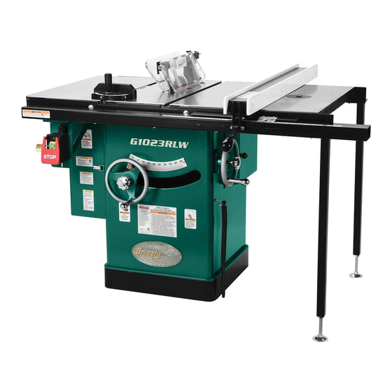
MODEL G1023RL SERIES
10" LEFT-TILT TABLE SAW
WITH RIVING KNIFE
OWNER'S MANUAL
(For RL/RLW/RLX models manufactured since 12/11)
(For RLWX models manufactured since 10/14)
G1023RLX
G1023RLW/RLWX
G1023RL
177335
COPYRIGHT © MAY, 2010 BY GRIZZLY INDUSTRIAL, INC. REVISED OCTOBER, 2014 (BLMN)
WARNING: NO PORTION OF THIS MANUAL MAY BE REPRODUCED IN ANY SHAPE
OR FORM WITHOUT THE WRITTEN APPROVAL OF GRIZZLY INDUSTRIAL, INC.
#BL12898 PRINTED IN TAIWAN
V3.10.14
Advertisement
Table of Contents

Related Manuals for Grizzly G1023RLX


Summary of Contents for Grizzly G1023RLX
- Page 1 G1023RLW/RLWX G1023RL 177335 COPYRIGHT © MAY, 2010 BY GRIZZLY INDUSTRIAL, INC. REVISED OCTOBER, 2014 (BLMN) WARNING: NO PORTION OF THIS MANUAL MAY BE REPRODUCED IN ANY SHAPE OR FORM WITHOUT THE WRITTEN APPROVAL OF GRIZZLY INDUSTRIAL, INC. #BL12898 PRINTED IN TAIWAN...
- Page 2 This manual provides critical safety instructions on the proper setup, operation, maintenance, and service of this machine/tool. Save this document, refer to it often, and use it to instruct other operators. Failure to read, understand and follow the instructions in this manual may result in fire or serious personal injury—including amputation, electrocution, or death.
-
Page 3: Table Of Contents
G1023RL (All) Fence ........86 Blade Selection ..........29 G1023RL, W, WX Fence Rails ....87 Blade Installation.......... 30 G1023RLX Fence Rails ....... 88 Blade Guard Assembly ........ 31 G1023RLW, WX, Router Table & Guard ..89 Riving Knife ..........34 Machine Labels .......... -
Page 4: Introduction
The G1023RL features 2 cast iron wings; the G1023RLW and G1023RLWX feature a cast-iron router table extension; the G1023RLX features a heavy-duty extension table with 53" rip capacity. Model G1023RL Series (Mfd. Since 12/11) -
Page 5: Identification
Extension Table For Your Own Safety Read Instruction Manual Before Operating Saw a) Wear eye protection. G1023RLX b) Use saw-blade guard and spreader for every operation for which it can be used, including all through sawing. Router Table Extension Wing c) Keep hands out of the line of saw blade. -
Page 6: Machine Data Sheet
Machine Data Sheet MODEL G1023RL Series 10" LEFT-TILTING TABLE SAWS Model Number G1023RL G1023RLX G1023RLW G1023RLWX Motor 3 HP, 240V, 1-Ph 3 HP, 240V, 1-Ph 3 HP, 240V, 1-Ph 5 HP, 240V, 1-Ph Required Power Supply Circuit 15 Amps 15 Amps... -
Page 7: Section 1: Safety
SECTION 1: SAFETY For Your Own Safety, Read Instruction Manual Before Operating This Machine The purpose of safety symbols is to attract your attention to possible hazardous conditions. This manual uses a series of symbols and signal words intended to convey the level of impor- tance of the safety messages. - Page 8 WEARING PROPER APPAREL. Do not wear FORCING MACHINERY. Do not force machine. clothing, apparel or jewelry that can become It will do the job safer and better at the rate for entangled in moving parts. Always tie back or which it was designed. cover long hair.
-
Page 9: Additional Safety For Table Saws
Additional Safety for Table Saws HAND & BODY POSITIONING. Touching a spin- FENCE. Make sure the fence remains properly ning saw blade will cause serious laceration or adjusted and parallel with the blade. Always lock amputation injuries. Keep hands away from saw the fence in place before using. -
Page 10: Preventing Kickback
Preventing Kickback • Never move the workpiece backwards or try to back it out of a cut while the blade is mov- ing. If you cannot complete a cut for some reason, stop the saw motor and allow the Take the precautions below to avoid the most blade to completely stop before backing the common causes of kickback: workpiece out. -
Page 11: Glossary Of Terms
The following is a list of common definitions, terms and phrases used throughout this manual as they relate to this table saw and woodworking in general. Become familiar with these terms for assembling, adjusting or operating this machine. Your safety is VERY important to us at Grizzly! Arbor: A metal shaft extending from the drive... -
Page 12: Section 2: Power Supply
SECTION 2: POWER SUPPLY Availability Circuit Information Before installing the machine, consider the avail- A power supply circuit includes all electrical ability and proximity of the required power supply equipment between the breaker box or fuse panel circuit. If an existing circuit does not meet the in the building and the machine. -
Page 13: Grounding Requirements
Circuit Requirements for G1023RLWX This machine is prewired to operate on a power supply circuit that has a verified ground and meets the following requirements: Nominal Voltage ..208V, 220V, 230V, 240V Cycle ............60 Hz Phase ..........Single Phase Circuit Rating ........30 Amps No adapter should be used with the plug. -
Page 14: Section 3: Setup
SECTION 3: SETUP Needed for Setup This machine presents serious injury hazards The following are needed to complete the setup to untrained users. Read process, but are not included with your machine. through this entire manu- al to become familiar with Description the controls and opera- •... -
Page 15: Hardware Recognition Chart
Hardware Recognition Chart -13- Model G1023RL Series (Mfd. Since 12/11) -
Page 16: Inventory
Inventory The following is a list of items shipped with your machine. Before beginning setup, lay these items out and inventory them. If any non-proprietary parts are missing (e.g. a nut or a washer), we will gladly replace them; or for the sake of expediency, replacements can be obtained at your local hardware store. - Page 17 Only the hardware needed to mount the fence B. Clamp Assemblies ........4 C. Table Insert 29mm ........1 to your Grizzly saw is listed in this inventory and shown in Figure 6. To avoid confusion, we sug- D. Table Insert 60mm ........1 E.
- Page 18 • Hex Bolts ⁄ "-16 x 1 ⁄ " (Rtr Table/Rail) ..2 Grizzly saw is listed in this inventory and shown in • Lock Washers ⁄ " (Rtr Table/Rail) ....2 Figure 9. To avoid confusion, we suggest remov- •...
-
Page 19: Cleanup
Cleanup Gasoline and petroleum products have low flash The unpainted surfaces of your machine are points and can explode coated with a heavy-duty rust preventative that or cause fire if used to prevents corrosion during shipment and storage. clean machinery. Avo i d This rust preventative works extremely well, but it u sing t h e s e p r o du c t s will take a little time to clean. -
Page 20: Site Considerations
Only install in an Shadows, glare, or strobe effects that may distract access restricted location. or impede the operator must be eliminated. G1023RL/RLW/RLWX G1023RLX Access Door Swing at 90º Access Door Swing at 90º Dust Port Dust Port 47"... -
Page 21: Assembly
Assembly Remove the motor brace shown in Figure 13 then. The brace is installed to prevent ship- ping damage. Assembly steps are the same for all models except where noted. Assembly consists of install- ing the left extension wing, ON/OFF switch, motor cover, dust port, rails, saw blade, table insert, Brace blade guard, fence scale, and cursor. - Page 22 (see Figure Model G1023RLX: Do not mount the exten- 14). sion table yet. Mount it to the right side of the table after the fence rails and rail tube are installed.
- Page 23 11. Mount the switch brace, as shown in Figure 14. Mount the fence resting brackets with (4) 17, using the pre-installed table mounting fas- M5-.8 x 8 button head cap screws, as shown in Figure 20. teners on the top end and the switch mount- ing fasteners on the bottom end.
-
Page 24: Rails & Fence
" hex bolts and ⁄ " flat washers to loosely attach the braces to the To install the Model G1023RLX extension table legs. (These will be adjusted and fully tight- and legs: ened later.) With the help of another person to hold the Use the (2) ⁄... -
Page 25: Saw Blade
Table Insert Use (2) ⁄ "-16 x ⁄ " hex bolts and ⁄ " flat washers to loosely attach the braces to the legs. (These will be adjusted and fully tight- ened later.) To install the table insert: Use the (2) ⁄... -
Page 26: Scale & Cursor
Scale & Cursor To connect a dust collection hose: Fit a 4" dust hose over the dust port, as shown in Figure 27, and tightly secure in Install the scale and cursor now on the Shop Fox place with a hose clamp. Classic Fence, using the instructions provided with the fence. -
Page 27: Test Run
Test Run Insert the padlock shaft through the ON but- ton, as shown in Figure 28. Test run your machine to make sure it runs prop- erly and is ready for regular operation. Padlock The test run consists of verifying the following: Shaft 1) The motor powers up and runs correctly, and ON / START... -
Page 28: Section 4: Operations
Handwheel Regardless of the content in this section, Figure 30. Basic table saw controls. Grizzly Industrial will not be held liable for accidents caused by lack of training. -26- Model G1023RL Series (Mfd. Since 12/11) -
Page 29: Operation Overview
Operation Overview Disabling & Locking Switch The purpose of this overview is to provide the novice machine operator with a basic understand- The switch can be disabled and locked by insert- ing of how the machine is used during a typical ing a padlock through the ON/START button, as operation, so the controls/components discussed shown. -
Page 30: Non-Through & Through Cuts
Non-Through & Stock Inspection Through Cuts Some workpieces are not safe to cut or may require modification before they are safe to cut. Non-Through Cuts Before cutting, inspect all workpieces for the following: A non-through cut is a sawing operation where the blade does not protrude above the top face of •... -
Page 31: Blade Requirements
Blade Requirements Crosscut blade features: • Best for cutting across the grain • 60-80 teeth • Alternate top bevel tooth profile To ensure that the spreader or riving knife works • Small hook angle and a shallow gullet safely, the following requirements MUST be met when installing new blades: •... -
Page 32: Blade Installation
Blade Installation Laminate blade features: • Best for cutting plywood or veneer • 40-80 teeth • Triple chip tooth profile • Very shallow gullet The saw blade is sharp. Use extra care and wear gloves when installing the blade. To install a new blade: Triple DISCONNECT SAW FROM POWER! Chip... -
Page 33: Blade Guard Assembly
Spreader Re-install the arbor flange and the arbor nut, and tighten them against the blade with the The spreader is a metal plate that prevents the wrenches included with the saw. DO NOT newly cut kerf of the workpiece from pinching the overtighten. - Page 34 Loosen the top knob on the blade guard, slide Place the right spreader pawl in the arresting the pins on the guard into the spreader slots, spring, then place a straightedge against the move the guard back, then tighten the top blade and the spreader.
- Page 35 Anti-Kickback Pawls Rotate one or both of the pawls upward, then place the arresting hook(s) in the arresting The anti-kickback pawls allow the workpiece to spring, as shown in Figure 46. travel in only one direction. If the workpiece moves backwards, such as during a kickback, the pawls will dig into the workpiece to slow or stop it.
-
Page 36: Riving Knife
Riving Knife To ensure that the riving knife works safe- ly, it MUST be aligned with and correctly The riving knife works in the same manner as adjusted to the blade. Refer to Page 64 to the spreader on the blade guard assembly. It is a check or adjust the riving knife alignment. -
Page 37: Ripping
Ripping Note: The jointed edge of the workpiece must slide against the fence during the cut- ting operation. "Ripping" means cutting with the grain of a natu- 10. Use a push stick to feed the workpiece ral wood workpiece. In other man-made materials through the saw blade, as shown in Figure such as MDF or plywood, ripping simply means 49 until the workpiece is completely beyond... -
Page 38: Crosscutting
Crosscutting Miter Cuts "Crosscutting" means cutting across the grain of A miter is an angled crosscut. Miters are usually a natural wood workpiece. In other man-made cut in the same manner as crosscuts, using the materials, such as MDF or plywood, crosscutting miter gauge and a predetermined mark on the means cutting across the width of the workpiece. -
Page 39: Blade Tilt/Bevel Cuts
Blade Tilt/Bevel Cuts Installing a Dado Blade DISCONNECT SAW FROM POWER! When the blade tilt stop bolts are properly adjust- Remove the table insert, the blade guard ed (Page 59), the blade tilt handwheel allows the assembly or riving knife, and the saw blade. operator to tilt the blade to the left, between 0°... - Page 40 Cutting Dadoes with a Dado Blade To cut a dado with a dado blade: The Figure below demonstrates the sequential Adjust the dado blade to the desired depth of process of making multiple, light cuts that get cut. progressively deeper. The actual number of cuts used should be determined by workpiece hard- Adjust the distance between the fence and the ness, total dado depth, and feed rate.
- Page 41 Cutting Dadoes with a Standard Reconnect the saw to the power source and turn the saw ON. Allow the blade to reach full Blade speed, then perform the cutting operation. A ripping blade (described on Page 29) is typically the best blade to use for cutting dadoes when Repeat the cutting operation on the other using a standard blade, because it removes saw- side of the dado channel, as shown in Figure...
-
Page 42: Rabbet Cutting
Rabbet Cutting Always use push sticks, featherboards, push paddles and other safety accessories Commonly used in furniture joinery, a rabbet is an whenever possible to increase safety and L-shaped groove cut in the edge of the workpiece. control during operations which require Rabbets can be cut with either a dado blade or a that the blade guard be removed from the standard saw blade. - Page 43 Cutting Rabbets with a Standard Blade A ripping blade is typically the best blade to use for cutting rabbets when using a standard blade because it removes sawdust very efficiently. (See Page 29 for blade details.) Also, a sacrificial fence is not required when cutting rabbets with a stan- dard blade.
-
Page 44: Resawing
Resawing Making Resaw Barrier The resaw barrier acts in tandem with the rip fence when resawing to provide tall support for the workpiece to minimize the probability of it binding against the blade and causing kickback. Resawing on a table saw increases the Tools Needed for the Resaw Barrier: chances of kickback. -
Page 45: Auxiliary Fence
Auxiliary Fence Attach the fence face (removed in Step 2) and the auxiliary fence to the fence body The auxiliary fence is necessary if you are with (6) #8 x 2" wood screws. The end result resawing a workpiece that is more than 3" tall. It should be similar to Figure 63. - Page 46 Install a ripping blade, install the riving knife, lower the blade below the table surface, then install the optional Model H4231. Make sure Always use push sticks or push paddles to the center section of the insert has already increase safety and control during opera- been removed—so the blade can be raised tions which require that the blade guard correctly in the following steps.
-
Page 47: Section 5: Shop Made Safety Accessories
SECTION 5: SHOP MADE SAFETY ACCESSORIES Featherboards We recommend using a bandsaw for making fingers in the next step because it tends to Easily made from scrap stock, featherboards be safer. A table saw can be used, but it will provide an added degree of protection against over-cut the underside of the ends, produce kickback, especially when used together with... - Page 48 Rout a ⁄ "– ⁄ " wide slot 4"–5" long in the Drill a ⁄ " hole in the center of the bar, then workpiece and 1"–2" from the short end of the countersink the bottom to fit a ⁄ "-20 flat head featherboard (see Figure 67).
- Page 49 Mounting Featherboards w/Clamps Mounting Featherboard in Miter Slot Lower the saw blade, then adjust the fence to Lower the saw blade, then adjust the fence to the desired width and secure it. the desired width and secure it. Place the workpiece against the fence, mak- Place the workpiece evenly against the fence, ing sure it is 1"...
-
Page 50: Push Sticks
Push Sticks Supporting: A second push stick can be used to keep the workpiece firmly against the fence while cutting. When using a push stick in this manner, only apply pressure before the blade; otherwise, When used correctly, push sticks reduce the risk pushing the workpiece against or behind the of injury by keeping hands away from the blade blade will increase the risk of kickback (see "Push... -
Page 51: Push Blocks
Push Blocks The notched end of the push block is then used to push the workpiece the rest of the way through the cut, keeping the operator's hands at a safe distance from the blade. A push stick is often When used correctly, a push block reduces the used at the same time in the other hand to sup- risk of injury by keeping hands away from the... -
Page 52: Narrow-Rip Auxiliary Fence & Push Block
Narrow-Rip Auxiliary Pre-drill and countersink eight pilot holes ⁄ " from the bottom of the 3" wide board, then Fence & Push Block secure the boards together with eight #8 x " wood screws, as shown in Figure 79. ⁄ There are designs for hundreds of specialty jigs #8 x 1 ⁄... - Page 53 Using the Auxiliary Fence and Push Place the workpiece 1" behind the blade and Block evenly against the table and the auxiliary fence (see Figure 82). Place the auxiliary fence on the table and clamp it to the fence at both ends, then adjust the distance between the auxiliary fence and Auxilliary Fence the blade—this determines how wide the...
-
Page 54: Outfeed & Support Tables
Outfeed & Support Crosscut Sled Tables A crosscut sled (see Figure 85) is a fantastic way to improve the safety and accuracy of cross- One of the best accessories for improving the cutting on the table saw. Most expert table saw safety and ease of using a table saw is simply plac- operators use a crosscut sled when they have ing a large table (outfeed table) behind the saw to... -
Page 55: Section 6: Accessories
(up to 44") as well as front to back. Very To reduce this risk, only install accessories versatile! recommended for this machine by Grizzly. NOTICE Refer to our website or latest catalog for additional recommended accessories. - Page 56 Master Plate for a precision measurement, with no runout! Figure 91. Universal overarm blade guard. Figure 93. Superbar™ and Master Plate. www.grizzly.com 1-800-523-4777 order online at or call -54- Model G1023RL Series (Mfd. Since 12/11)
-
Page 57: Section 7: Maintenance
SECTION 7: MAINTENANCE Cleaning Always disconnect power to the machine before Cleaning the Model G1023RL series table saw is performing maintenance. relatively easy. Vacuum excess wood chips and Failure to do this may sawdust, and wipe off the remaining dust with a result in serious person- dry cloth. -
Page 58: Lubrication
Lubrication Worm Gear, Bevel Gears, and Blade Angle Teeth Check every month. Use a stiff bristle brush and mineral spirits to clean away any built up grime It is essential to clean components before lubri- and debris from the worm gear, bevel gear, and cating them because dust and chips build up on blade angle trunnion teeth (see Figure 95). -
Page 59: Section 8: Service
SECTION 8: SERVICE Review the troubleshooting and procedures in this section to fix or adjust your machine if a problem devel- ops. If you need replacement parts or you are unsure of your repair skills, then feel free to call our Technical Support at (570) 546-9663. - Page 60 Symptom Possible Cause Possible Solution Handwheel binds or 1. Lock knob is engaged. 1. Loosen lock knob. is difficult to move. 2. Handwheel shaft pins are wedged. 2. Remove handwheel and adjust shaft pins. 3. Handwheel is inserted too far. 3.
-
Page 61: Blade Tilt Stops
Blade Tilt Stops —If the blade is 90° to the table, then adjust- ments do not need to be made. Make sure the tilt indicator arrow shown in Figure 98 points to the 0° mark on the scale. If it does The table saw features stop bolts that stop the not, remove the blade height lock knob, blade exactly at 45°... - Page 62 Setting 45° Stop Bolt Open the motor cover, loosen the jam nut shown in Figures 99–100, adjust the stop DISCONNECT SAW FROM POWER! bolt up or down according to how far off the blade was from 90°, then repeat Steps 2-3 Raise the blade as high as it will go, then tilt it until the blade stops at 90°.
-
Page 63: Miter Slot To Blade Parallelism
Miter Slot to Blade Open the right access door. Parallelism Tilt the blade as needed so there is enough room to adjust the stop bolt. Loosen the jam nut on the 45° stop bolt (see Your table saw will give the best results if the Figure 102) then adjust the stop bolt in or out miter slot is parallel with the blade. - Page 64 Rotate the marked blade tip to the other end Tilt the blade to 45° and repeat Steps 3-6. of the table insert. —If the blade is still parallel with the miter slot Compare the distance from the marked blade no further adjustments need to be made. tip to the miter slot, as shown in Figure 105.
-
Page 65: Blade Alignment
Blade Alignment 11. Tighten one bolt a small amount and then move on to each of the others, tightening each down the same amount. Continue to rotate through the bolts, tightening them a If the blade contacts the table insert when raised little each time until they are all secure. -
Page 66: Spreader Or Riving Knife Alignment
Spreader or Riving Adjusting Blade Position by Moving Trunnion Knife Alignment DISCONNECT SAW FROM POWER! Remove the table and wings and set them to Checking Alignment one side. The blade guard spreader and riving knife must be aligned with the blade when installed. If the spreader/riving knife is not aligned with the blade, then the workpiece will be forced sideways during The table and wings are... - Page 67 Adjusting Alignment The spreader/riving knife should be parallel with the blade along its length at both posi- The spreader/riving knife mounts to a block that tions and should be in the "Alignment Zone," can be repositioned to correctly align the spread- as shown in Figure 111.
-
Page 68: Fence Adjustments
Fence Adjustments Loosen the two cap screws on the mounting block, then adjust the set screws on the block to move it in the necessary direction (see "Mounting Block" inset in Figure 112). There are three main adjustments for the Shop Fox Classic fence: (1) height, (2) parallelism, and Re-install the table insert and spreader/riving (3) clamping pressure. - Page 69 Check the fence support pads. Over time Slide the fence up against the right hand edge the pads illustrated in Figure 115 will wear. of the miter slot, lock it in place, then raise the Replace them if they appear worn. blade to its maximum height.
- Page 70 To adjust the fence clamping pressure and Use trial-and-error to adjust the set screws parallelism to the blade: (see Figure 117) so the fence is parallel with the blade and the clamping pressure is suf- DISCONNECT SAW FROM POWER! ficient. Optional: Some woodworkers prefer to off- Remove the fence and equally adjust the set screws shown in Figure 117 as necessary,...
-
Page 71: Fence Scale Calibration
Fence Scale Miter Gauge Calibration Adjustments The miter gauge (see Figure 121) is equipped The fence scale indicator window, shown in Figure 120, can be calibrated with the fence with stop screws that allow you to easily adjust scale if you notice that your cuts do not accurately the miter gauge from 45°... - Page 72 Checking/Setting 45° Stops Pivot the miter gauge body so the 90° stop screw rests against the stop link, then tighten Follow the same process with the 45° stops that the lock knob. you followed with the 90°, except using a 45° square or adjustable square to verify that the miter Place the square evenly against the face of body is 45°...
-
Page 73: Belt Tension & Replacement
Belt Tension & Loosen the two hex bolts on the motor (see Figure 125), and pivot the motor up and Replacement down to make sure that it is movable. Hex Bolt The belt stretches slightly as the saw is used. Most of the belt stretching will happen during the first 16 hours of use, but it may continue in small increments through continued use. -
Page 74: Replacing Belt
Replacing Belt Loosen the motor adjustment bolt (see Figure 125 on Page 71). DISCONNECT SAW FROM POWER! 10. Remove the three Phillips head screws on Remove the table insert. the bearing retainer, shown in Figure 129, then remove the retainer. Remove the ON/OFF switch from the table. - Page 75 12. Loosen the set screws shown in Figure 131. 16. Tap the rear arbor bearing out; make sure another person catches the bearing. Set Screws 17. Remove the key and the larger front spacer from the arbor and set these aside. 18.
- Page 76 21. Re-install the larger front spacer and key onto 27. Use a block of wood to seat a new 6203-2RS the arbor. The arbor should look like the one bearing (Part P1023RL100) into the end of shown in Figure 136. the arbor.
-
Page 77: Gib Adjustment
Gib Adjustment Tools Needed Wrench or Socket 12mm ........1 Hex Wrench 4mm ..........1 The Model G1023RL has an elevation slide gib To adjust the elevation slide gib: that can be adjusted to ensure smooth, consistent movement of the arbor. DISCONNECT SAW FROM POWER! When adjusting the elevation slide gib, the goal Loosen the hex nuts securing the four adjust-... -
Page 78: Section 9: Wiring
Technical Support at (570) 546-9663. The photos and diagrams included in this section are best viewed in color. You can view these pages in color at www.grizzly.com. -76- Model G1023RL Series (Mfd. Since 12/11) -
Page 79: G1023Rl/Rlx/Rlw Electrical Components
G1023RL/RLX/RLW Electrical Components 3HP, 240V, 1-Ph Figure 139. On/Off Switch. Figure 141. Magnetic switch. Figure 140. Motor junction box. READ ELECTRICAL SAFETY -77- Model G1023RL Series (Mfd. Since 12/11) ON PAGE 76! -
Page 80: G1023Rl/Rlx/Rlw Wiring
G1023RL/RLX/RLW Wiring 3HP, 240V, 1-Ph 3HP 240V 1-Ph Motor (See Figure 140) 220V-240V Single-Phase S Capacitor 60 Hz 600M 125V Ground 240V On/Off Switch (See Figure 139) 6-15 Plug 3HP 240V 1-Ph Motor (Included) S Capacitor 600M 125V L1/1 L2/3 L3/5 Ground MA-09... -
Page 81: G1023Rlwx Electrical Components
G1023RLWX Electrical Components 5HP, 240V, 1-Ph Figure 142. Run capacitor. Figure 145. Start capacitor. Figure 143. On/Off Switch. Figure 146. Magnetic switch. Figure 144. Motor junction box. READ ELECTRICAL SAFETY -79- Model G1023RL Series (Mfd. Since 12/11) ON PAGE 76! -
Page 82: G1023Rlwx Wiring
Switch NO14 Assembly MPE-18 G1023RLWX Wiring 5HP, 240V, 1-Ph SDE RA-30 5HP 240V 1-Ph Motor 220V–240V Single-Phase (See Figures 142, 144, 145) 60 Hz L6-30 Plug Start Capacitor (Included) 400M 125V L6-30 Plug (Included) Run Capacitor 60M 300V On/Off Switch 220V–240V (See Figure 143) Single-Phase... -
Page 83: Section 10: Parts
SECTION 10: PARTS G1023RL (All) Main 26-3 26V3 26-1 26-3V2 26-1 26-2 26-4 (G1023RLWX) 26-2 26-4V3 19-1 24-1 20-2 19V2 20-1 21-1 10-1 26-5 19V2 27V2 (G1023RLWX) -81- Model G1023RL Series (Mfd. Since 12/11) - Page 84 DUST HOSE HOOK P1023RL020 PADDLE SWITCH P1023RL140 CABLE TIE 20-1 P1023RL020-1 SWITCH BOX G8588 GRIZZLY LOGO PLATE SMALL 20-2 P1023RL020-2 SWITCH DISABLING LOCK PLABEL-14 ELECTRICITY LABEL 1.4W X 1.2H PS08 PHLP HD SCR 10-24 X 3/4 PHTEK28 TAP SCREW #4 X 3/8...
-
Page 85: G1023Rl (All) Arbor & Motor
G1023RL (All) Arbor & Motor -83- Model G1023RL Series (Mfd. Since 12/11) - Page 86 G1023RL (All) Arbor & Motor Parts REF PART # DESCRIPTION REF PART # DESCRIPTION PW07 FLAT WASHER 5/16 P1023SL026 TILT SHAFT PLW01 LOCK WASHER 5/16 P1023027 SHAFT PIN 35-1 PCAP08 CAP SCREW 5/16-18 X 1-1/2 PK15M KEY 5 X 5 X 35 PB03 HEX BOLT 5/16-18 X 1 PB04...
-
Page 87: G1023Rl (All) Blade Guard & Miter Gauge
G1023RL (All) Blade Guard & Miter Gauge REF PART # DESCRIPTION REF PART # DESCRIPTION P1023RL300 BLADE GUARD ASSEMBLY PRP73M ROLL PIN 4 X 30 P1023RL301 SUPPORT ARM PS01 PHLP HD SCR 10-24 X 1/2 P1023RL302 RIGHT GUARD P1023RL324 FRONT BRACKET P1023RL303 LEFT GUARD P1023RL325... -
Page 88: G1023Rl (All) Fence
G1023RL (All) Fence 508-1 REF PART # DESCRIPTION REF PART # DESCRIPTION P1023SL501 FENCE LOCKING TAB P1023RL523 SET SCREW 3/8-16 X 5/16 P8826002A FENCE LOCK KNOB PLN02 LOCK NUT 1/4-20 P8826003 BEARING PAD PLN01 LOCK NUT 3/8-16 P8826004 LOCKING LEVER PW03 FLAT WASHER #10 P1023SL508... -
Page 89: G1023Rl, W, Wx Fence Rails
G1023RL, W, WX Fence Rails 517-1 516-1 REF PART # DESCRIPTION REF PART # DESCRIPTION P1023SL514 SCALE 26" PFH05 FLAT HD SCR 1/4-20 X 3/4 P1023SL515 FRONT RAIL TUBE 54" PW06 FLAT WASHER 1/4 PB05 HEX BOLT 1/4-20 X 3/4 PW02 FLAT WASHER 3/8 516-1 P1023SL516A FRONT RAIL 46-1/2"... -
Page 90: G1023Rlx Fence Rails
G1023RLX Fence Rails 510-1 REF PART # DESCRIPTION REF PART # DESCRIPTION P1023SLX506 EXTENSION LEG PW02 FLAT WASHER 3/8 P1023SLX507 FRONT RAIL TUBE 84" PW06 FLAT WASHER 1/4 P9221010 REAR RAIL 72" PN05 HEX NUT 1/4-20 510-1 P9221010A FRONT RAIL 72"... -
Page 91: G1023Rlw, Wx, Router Table & Guard
G1023RLW, WX, Router Table & Guard 612-1 620-12 620-1 620-8 620-2 620-3 620-6 620-8 620-4 620-5 620-7 620-11 620-8 620-9 620-10 PART # DESCRIPTION PART # DESCRIPTION P1023SLW601 ROUTER TABLE EXT WING PFH05 FLAT HD SCR 1/4-20 X 3/4 P1023SLW602 TABLE INSERT 29MM PW06 FLAT WASHER 1/4... -
Page 92: Machine Labels
COPYRIGHT © GRIZZLY INDUSTRIAL, INC. FOR GRIZZLY MACHINES ONLY! All labels created by Grizzly Industrial, Inc. are copyrighted and must only be used on Grizzly brand machines. Never use Grizzly’s label artwork on other brands of machines. G1023RL Labels B... -
Page 93: Warranty Card
Would you recommend Grizzly Industrial to a friend? _____ Yes _____No Would you allow us to use your name as a reference for Grizzly customers in your area? Note: We never use names more than 3 times. _____ Yes _____No 10. - Page 94 FOLD ALONG DOTTED LINE Place Stamp Here GRIZZLY INDUSTRIAL, INC. P.O. BOX 2069 BELLINGHAM, WA 98227-2069 FOLD ALONG DOTTED LINE Send a Grizzly Catalog to a friend: Name_______________________________ Street_______________________________ City______________State______Zip______ TAPE ALONG EDGES--PLEASE DO NOT STAPLE...
-
Page 95: Warranty And Returns
WARRANTY AND RETURNS Grizzly Industrial, Inc. warrants every product it sells for a period of 1 year to the original purchaser from the date of purchase. This warranty does not apply to defects due directly or indirectly to misuse, abuse, negligence, accidents, repairs or alterations or lack of maintenance.