Table of Contents
Advertisement
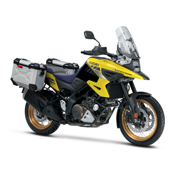
2022 V-STROM 1050 / 1050XT
Operating, servicing and maintaining a passenger
vehicle or off-road vehicle can expose you to chemicals
including
phthalates, and lead, which are known to the State of
California to cause cancer and birth defects or other
reproductive harm. To minimize exposure, avoid
breathing exhaust, do not idle the engine except as
necessary, service your vehicle in a well-ventilated area
and wear gloves or wash your hands frequently when
servicing your vehicle. For more information go to
www.P65Warnings.ca.gov/passenger-vehicle.
This manual should be considered a permanent part of the
motorcycle and should remain with the motorcycle when resold or
otherwise transferred to a new owner or operator. The manual
contains important safety information and instructions which should
be read carefully before operating the motorcycle.
California Proposition 65 Warning
WARNING
engine
exhaust,
carbon
monoxide,
Advertisement
Chapters
Table of Contents

Related Manuals for Suzuki V-STROM 1050 2022


Summary of Contents for Suzuki V-STROM 1050 2022
- Page 1 2022 V-STROM 1050 / 1050XT California Proposition 65 Warning WARNING Operating, servicing and maintaining a passenger vehicle or off-road vehicle can expose you to chemicals including engine exhaust, carbon monoxide, phthalates, and lead, which are known to the State of California to cause cancer and birth defects or other reproductive harm.
- Page 2 FOREWORD closely to ensure emission compliance. Your Suzuki dealer has experienced Motorcycling is one of the most exhila- technicians that are trained to provide rating sports and to ensure your riding your machine with the best possible...
- Page 3 Suzuki Motor Corporation believes in conservation and protection of Earth’s natural resources. To that end, we encourage every vehicle owner to recy- cle, trade in, or properly dispose of, as appropriate, used motor oil, coolant, and other fluids, batteries and tires.
- Page 4 IMPORTANT CAUTION Indicates a potential hazard that WARNING/ CAUTION/NOTICE/ could result in minor or moderate NOTE injury. Please read this manual and follow its instructions carefully. To emphasize NOTICE special information, the symbol words WARNING, CAUTION, Indicates a potential hazard that NOTICE and NOTE have special mean- could result in vehicle or equipment ings.
-
Page 6: Table Of Contents
TABLE OF CONTENTS SAFETY INFORMATION CONTROLS, EQUIPMENT AND ADJUSTMENTS INSPECTION AND MAINTENANCE TROUBLESHOOTING STORAGE PROCEDURE AND MOTORCYCLE CLEANING CONSUMER INFORMATION SPECIFICATIONS INDEX... -
Page 8: Safety Information
SAFETY INFORMATION SAFETY GUIDELINES ..........................1-2 RIDING PRECAUTIONS ........................... 1-17 FUEL GUIDELINES ..........................1-30 LABELS ..............................1-33 ACCESSORY USE AND MOTORCYCLE LOADING ................1-37 MODIFICATION ............................1-41... -
Page 9: Safety Guidelines
• Do not turn the handlebars swiftly or SAFETY INFORMATION ride with one hand, as this may cause skidding or falls. • To minimize injuries caused by falls SAFETY GUIDELINES or crashes, wear protective equip- ment such as helmets and gloves. MOST ACCIDENTS CAN BE information appropriate... - Page 10 If the motorcycle makes an unusual suspension and tires can be over- sound, smells, or leaks fluid, have it loaded. Refer to “ACCESSORY USE inspected by a Suzuki dealer. For infor- AND MOTORCYCLE LOADING” on mation on routine checks and periodic page 1-37.
- Page 11 WARNING WARNING Riding excessive speeds If you remove even one hand or foot increases your chances of losing from the motorcycle, you can reduce control of the motorcycle, which can your ability to control the motorcy- result in a crash. cle.
- Page 12 PROTECTIVE APPAREL Helmet • Be sure to wear a helmet and tighten Description the strap firmly. Choose a helmet Both rider and passenger should be that fits your head snugly but does sure to wear helmets, as well as cloth- not exert excessive pressure.
- Page 13 Riding gear WARNING • Wear protective equipment clothing that affords a high level of If you don’t wear a helmet, you have protection. Wear bright, eye-catch- an increased risk of death or severe ing long-sleeved uppers and full- injury in a crash. If you wear a helmet length trousers that expose a mini- that doesn’t fit properly or is not mum of skin.
- Page 14 Gear of a passenger WARNING A passenger needs the same protection that you do, including a helmet and If the person in the rear seat wears a proper clothing. The passenger should long jacket or coat, they may not wear long shoe laces or loose pants obscure the tail light or turn signal that could get caught in the wheel or the light.
- Page 15 IF A COLLISION IS IMMINENT, DO Emergency stopping and swerving are techniques that you should practice and SOMETHING Many riders fear locking up their brakes master before you find yourself in an emergency situation. The best place to or haven’t learned to swerve to avoid a crash.
- Page 16 SPECIAL SITUATIONS REQUIRE Rainy day, Snowy day SPECIAL CARE • When the road surface is wet, loose, or rough, you should brake with care. Windy day Braking distances increase on a rainy When riding in a strong crosswind, day. Stay off the painted surface which can occur at the entrance to a marks, manhole covers, and greasy- tunnel, on a bridge, or when passing or...
- Page 17 After riding on a flooded road, ask your cycle to fall over. Suzuki dealer to check for the following: • Braking efficiency • Wet connectors, wiring and water in...
- Page 18 KNOW YOUR LIMITS NOTICE Always ride within the boundaries of your own skills. Knowing these limits Riding the motorcycle on a flooded and staying within them will help you road can cause the engine to stop avoid crashes. running, and can cause failure of electric parts, drive belt slipping and A major cause of crashes involving only engine damage.
- Page 19 Riding a motorcycle safely requires that PRACTICE AWAY FROM TRAFFIC your mental and physical skills are fully Your riding skill and your mechanical part of the experience. You should not knowledge form the foundation for safe attempt to operate a motor vehicle, riding practices.
- Page 20 CARRYING A PASSENGER You may also need to adjust tire pres- This motorcycle has a capacity of two sures and suspension; please refer to people. Do not attempt to ride while car- the Tire Pressure and Loading section and the Suspension section for more rying more than...
- Page 21 Before you invite someone to be a pas- MOTORCYCLE SAFETY senger on your motorcycle, you need to FOUNDATION’S “RIDING TIPS AND be thoroughly familiar with motorcycle PRACTICE GUIDE” HANDBOOK operation. This special handbook, supplied with your owner’s manual, contains a variety Ensure that passengers understand the of safety tips, helpful hints, and practice following before they ride with you.
- Page 22 ABOUT CARBON MONOXIDE BE STREET SMART To prevent carbon monoxide poisoning, Always heed speed limits, local laws, start the engine in a well-ventilated and the basic rules of the road. Set a location. good example for others by demonstrat- Contained in exhaust gas, carbon mon- ing a courteous attitude and a responsi- oxide is a colorless odorless gas, and ble riding style.
- Page 23 USA can call toll- be attentive. free 1-800-446-9227. Circumstances beyond your control Good riding on your new Suzuki! could lead to a crash. You need to pre- pare for the unexpected by wearing a helmet and other protective gear, and...
-
Page 24: Riding Precautions
RIDING PRECAUTIONS Maximum Engine Speed Recommendation The table below shows the maximum BREAK-IN engine speed recommendation during the break-in period. Description The first 500 miles (800 km) is the most 500 miles Initial Below 4500 r/min important in the life of your motorcycle. (800 km) Proper operation during this break-in 1000 miles... - Page 25 Breaking in the new tires WARNING New tires need proper break-in to assure maximum performance, just as Failure to perform break-in of the the engine does. Wear- in the tread sur- tires could cause tire slip and loss of face by gradually increasing your cor- control.
- Page 26 Observe Your Initial and Most Critical ON HILLS Service Riding on a slope The initial service (break-in mainte- • When climbing steep hills, the nance) is the most important service your motorcycle will receive. During motorcycle may begin to slow down break-in operation, all of the engine and show lack of power.
- Page 27 PARKING WARNING How to park If you use the brakes continuously To prevent theft, be sure to lock the on long downhill roads, the brakes handlebars and remove the key when may overheat, reducing their effec- leaving the motorcycle. See “IGNITION tiveness.
- Page 28 • When parking the motorcycle on an CAUTION unstable surface such as an incline, on gravel, on an uneven surface, or Hot exhaust pipes and mufflers can on soft ground is unavoidable, be cause severe burns. The exhaust careful when leaning or moving it. pipe or muffler will be hot enough to ...
- Page 29 NOTE: ABOUT THE BRAKES • If the motorcycle is to be parked on the side stand on a slight slope, the What is ABS? front end of the motorcycle should ABS is a device that controls braking during riding to prevent the wheels from face “up”...
- Page 30 special braking operation The ABS may not function properly if the tires are replaced with non-specified required, as the ABS operates continu- ously except at low speeds below 5 tires. To ensure that the ABS functions correctly, use only the specified tires on mph (8 km/h) and when the battery has run down.
- Page 31 NOTE: In some situations, a motorcycle WARNING with ABS may require a longer stopping distance to stop on loose or uneven sur- Failure to use good judgment with faces than an equivalent motorcycle ABS can be hazardous. ABS cannot without ABS.
- Page 32 Motion Track Brake System Having ABS does not mean you can (V-STROM 1050XT) take unnecessary risks. ABS will not This model is equipped with a system compensate for poor judgment, incor- called the “Motion Track Brake System”. rect braking techniques, or not slowing This system controls ABS braking down over bad roads or in poor weather according to the motorcycle bank angle...
- Page 33 What is the load-dependent control Fluctuations in weight due to the num- ber of riders and the motorcycle loading system? (V-STROM 1050XT) often occur when the ignition switch is The load-dependent control system turned off, and the required braking controls the braking force of the front and rear brakes according to the num- force also changes, so the learned data ber of riders and the motorcycle loading...
- Page 34 In this situation, evenly and at the same time. the ABS is not operating. Immedi- 3. Downshift through the gears as road ately contact your Suzuki dealer if speed decreases. the indicators come on. 4. Select neutral with the clutch lever...
- Page 35 WARNING WARNING Inexperienced riders tend Braking while turning the motorcycle underuse the front brake. This can can be hazardous, whether or not cause excessive stopping distance your motorcycle is equipped with and lead to a crash. Using only the ABS.
- Page 36 WARNING WARNING Sudden braking and sudden down- Following another vehicle too closely shifting can impair riding stability can lead to a crash. As vehicle and cause side-slips and tumbles. speeds increase, stopping distance increases progressively. Avoid unnecessary sudden braking and sudden downshift.
-
Page 37: Fuel Guidelines
If the situation extends the lifespan of spark plugs and is not improved by changing, consult exhaust system parts. your Suzuki dealer. Fuel used: Unleaded premium gasoline Fuel tank capacity: 5.3/4.4 US/Imp. gal (20.0 L) 1-30... - Page 38 Oxygenated fuel recommendation Fuel Pump Labeling In some states, pumps that dispense Oxygenated fuels which meet the mini- oxygenated fuels are required to be mum octane requirement and the labeled for the type and percentage of requirements described below may be used in your motorcycle without jeopar- oxygenate, and whether important addi- dizing the New Vehicle Limited War-...
- Page 39 NOTE: NOTICE • help minimize pollution, Suzuki recommends that you use Spilled gasoline containing alcohol oxygenated fuels. can damage the painted surfaces of • Be sure that any oxygenated fuel your motorcycle. you use has octane ratings of at least 90 pump octane ((R+M)/2 Be careful not to spill any fuel when method).
-
Page 40: Labels
LABELS LOCATION OF LABELS Read and follow all of the warnings labeled on your motorcycle. Make sure you understand all of the labels. Keep the labels on your motorcycle. Do not remove them for any reason. 1-33... - Page 41 1-34...
- Page 42 V E H I C L E E M I S S I O N C O N T R O L I N F O R M AT I O N S U Z U K I M OTO R C O R P O R AT I O N D I S P L A C E M E N T : E N G I N E FA M I LY : P E R M E AT I O N FA M I LY :...
- Page 43 1-36...
-
Page 44: Accessory Use And Motorcycle Loading
The addition of unsuitable accessories can lead to unsafe operating conditions. Never use improper accessories, and It is not possible for Suzuki to test each make sure that any accessories that accessory on the market or combina- are used are properly installed. All tions of all the available accessories;... - Page 45 • Accessories fitted to the handlebars wiring harness or create hazardous situations. genuine Suzuki or the front fork area can create seri- ous stability problems. This extra accessories. weight will cause the motorcycle to be less responsive to your steering control.
- Page 46 LOADING G.V.W.R.: 440 kg (970 lbs) at the tire pressure (cold) Loading limit Front: 36 psi (250 kPa, 2.50 kgf/cm • Loading the motorcycle will make Rear: 42 psi (290 kPa, 2.90 kgf/cm the handling and safety characteris- WARNING tics of the motorcycle different than when it is not loaded.
- Page 47 Loading guidelines that protrude from the tail end out- side the body of the motorcycle. This motorcycle is primarily intended to • Check that both tires are properly carry small items when you are not rid- inflated to the specified tire pressure ing with a passenger.
-
Page 48: Modification
Do not carry any objects in the space behind the fairing. Suzuki’s limited warranties may not cover damage caused by modifications that would change the original vehicle specifications including, without limita- tion, modifications of any emission... - Page 49 This could result in an unsafe vehicle operating condition and subsequent crash. Suzuki will not be responsible in any way for personal injury or damage to the motorcycle caused by frame modifications.
- Page 50 • Mufflers engraved with “Suzuki” mark to indicate that they are genuine Suzuki parts. • Do not self-tune the engine or remove parts. Consult a Suzuki dealer regarding engine tuning. • We recommend that you use genu- ine Suzuki parts and specified/rec- ommended oils and lubricants for your motorcycle.
-
Page 52: Controls, Equipment And Adjustments
CONTROLS, EQUIPMENT AND ADJUSTMENTS NAMES OF PARTS AND LAYOUT DIAGRAM (PICTURE INDEX) ............2-2 INSTRUMENT PANEL ..........................2-24 RIDING ASSISTANCE SYSTEM SETTINGS ................... 2-68 IGNITION SWITCH ........................... 2-88 HANDLEBAR SWITCHES ........................2-93 STARTING THE ENGINE ......................... 2-98 REFUELING ............................2-105 SHIFTING GEARS .......................... - Page 53 CONTROLS, EQUIPMENT AND ADJUSTMENTS NAMES OF PARTS AND LAYOUT DIAGRAM (PICTURE INDEX) LOCATION OF PARTS Around the Handle V-STROM 1050...
- Page 54 Around the Handle V-STROM 1050 1 Clutch lever ( 2-114) 2 Left handlebar switches ( 2-14) 3 Clutch fluid reservoir ( 3-58) 4 USB socket ( 2-133) 5 Instrument panel ( 2-16) 6 Ignition switch ( 2-88) 7 Front brake fluid reservoir ( 3-61) 8 Right handlebar switches (...
- Page 55 Left Side View V-STROM 1050...
- Page 56 Left Side View V-STROM 1050 B Air cleaner ( 3-26) C Air cleaner drain plug ( 3-30) D Battery ( 3-20) E Fuse ( 3-100) F Tools ( 3-13) G Rear carrier ( 2-135) H Gearshift lever ( 2-107) ( 3-69) I Side stand (...
- Page 57 Right Side View V-STROM 1050...
- Page 58 Right Side View V-STROM 1050 M Rear brake fluid reservoir ( 3-61) N Engine coolant reservoir ( 3-44) O Rear brake light switch ( 3-67) P Rear brake pedal ( 2-113) ( 3-66) Q Engine oil filler cap ( 3-36) R Engine oil inspection window (...
- Page 59 Around the Handle V-STROM 1050XT...
- Page 60 Around the Handle V-STROM 1050XT 1 Clutch lever ( 2-114) 2 Left handlebar switches ( 2-14) 3 Clutch fluid reservoir ( 3-58) 4 USB socket ( 2-133) 5 Instrument panel ( 2-16) 6 Ignition switch ( 2-88) 7 Front brake fluid reservoir ( 3-61) 8 Right handlebar switches (...
- Page 61 Left Side View V-STROM 1050XT 2-10...
- Page 62 Left Side View V-STROM 1050XT B Air cleaner ( 3-26) C Air cleaner drain plug ( 3-30) D Battery ( 3-20) E Fuse ( 3-100) F Tools ( 3-13) G Output terminal ( 2-131) H Rear carrier ( 2-135) I Gearshift lever ( 2-107) ( 3-69) J Side stand (...
- Page 63 Right Side View V-STROM 1050XT 2-12...
- Page 64 Right Side View V-STROM 1050XT O Rear brake fluid reservoir ( 3-61) P Engine coolant reservoir ( 3-44) Q Rear brake light switch ( 3-67) R Rear brake pedal ( 2-113) ( 3-66) S Engine oil filler cap ( 3-36) T Engine oil inspection window (...
- Page 65 HANDLEBAR SWITCHES RIGHT HANDLEBAR LEFT HANDLEBAR 2-14...
- Page 66 LEFT HANDLEBAR 1 Dimmer switch/Headlight flasher switch ( 2-93) 2 Select switch ( 2-20) ( 2-22) 3 Mode switch ( 2-94) 4 Turn signal light switch ( 2-95) 5 Horn switch ( 2-94) RIGHT HANDLEBAR 6 Engine stop switch ( 2-96) 7 Electric starter switch (...
- Page 67 WARNING AND INDICATOR LIGHTS 2-16...
- Page 68 1 ABS indicator light ( 2-33) 2 Turn signal indicator light ( 2-25) 3 Engine rpm indicator light ( 2-25) 4 Traction control indicator light ( 2-26) 5 Neutral indicator light ( 2-27) 6 Malfunction indicator light ( 2-28) 7 Cruise control indicator light (V-STROM 1050XT) ( 2-28) 8 Master warning indicator light (...
- Page 69 2-18...
- Page 70 0 Oil pressure / engine coolant temperature / battery voltage warning indicator symbol ( 2-31) A Hill hold indicator (V-STROM 1050XT) ( 2-41) B Suzuki drive mode selector indicator (SDMS) ( 2-68) C Traction control system indicator ( 2-26) D ABS mode indicator (V-STROM 1050XT) ( 2-76) E Multifunction display (...
- Page 71 MULTIFUNCTION DISPLAY Normal mode : Select switch (Up) : Select switch (Down) 2-20...
- Page 72 1 Instantaneous Operate the select switch (Up or Down) fuel consumption to set each item in the multifunction dis- meter ( 2-47) 2 Trip meter A /average fuel consump- play. tion meter A ( 2-49) 3 Trip meter B /average fuel consump- tion meter B (...
- Page 73 Setting mode : Select switch (Up) for about 2 seconds : Select switch (Up) : Select switch (Down) 2-22...
- Page 74 Operate the select switch (Up or Down) 1 DATE&TIME to set each item in the multifunction dis- Set the date and time. ( 2-52) play. 2 RPM SET Set the engine rpm indicator light. ( 2-55) 3 UNIT Set the units. ( 2-61) 4 SERVICE Set the service interval notification.
- Page 75 INSTRUMENT PANEL INITIAL METER DISPLAY When you turn the ignition switch to ON, the meter will act as follows. All LCD 1 segments appear and • then show the normal display. • The following indicator lights come on for 3 seconds. - Malfunction indicator light 2 - Master warning indicator light 3 - Freeze indicator light 4...
- Page 76 TURN SIGNAL INDICATOR LIGHT ENGINE RPM INDICATOR LIGHT “ ” When engine speed reaches the set value, the engine RPM indicator light 1 Operate the right or left turn signal comes on or blinks to indicate when to switch to make the turn signal indicator blink.
- Page 77 The motorcycle is not functioning correctly if the traction control (TC) indicator does not turn off when the motorcycle is traveling at 6 mph (10 km/h) or faster. If the light does not go off, consult your Suzuki dealer. 2-26...
- Page 78 The traction control system does not operate in these circumstances. When these indicators come on at the same time, set the traction con- trol system to OFF, and consult your Suzuki dealer. 2-27...
- Page 79 If the malfunction indicator light comes on, “FI” appears on the multifunction display at the same time. For details, see “DIAGNOSIS DISPLAY” on page 2-45. NOTE: If the malfunction indicator light is lit or blinking, consult your Suzuki dealer immediately. 2-28...
- Page 80 Ambient temperature sensor failure For details, see “CRUISE CONTROL • Motorcycle falls over (V-STROM 1050XT)” on page 2-77. For details, see “DIAGNOSIS DISPLAY” on page 2-45. NOTE: If the master warning indicator light is lit or blinking, consult your Suzuki dealer immediately. 2-29...
- Page 81 HIGH BEAM INDICATOR LIGHT “” OIL PRESSURE / ENGINE COOLANT TEMPERATURE / BATTERY This blue indicator light will be lit when the headlight high beam is turned on. VOLTAGE WARNING INDICATOR LIGHT When the ignition switch is turned on, FREEZE INDICATOR LIGHT “ ”...
- Page 82 The oil pressure warning indicator sym- Oil Pressure Warning Indicator bol 2, engine coolant temperature Symbol “ ” warning indicator symbol 3 and battery When the ignition switch is turned on, charge malfunction warning indicator the oil pressure / engine coolant tem- symbol 4 appear in the LCD display.
- Page 83 Check the oil level and add oil ning the motorcycle. if necessary. If there is a proper amount of oil and the light still does not turn off, have your authorized Suzuki dealer qualified mechanic inspect your motorcycle. 2-32...
- Page 84 ” not operate when the ABS indicator This indicator comes on when battery light is on. performance is low, prompting you to have the battery inspected or charged. NOTE: Consult a Suzuki dealer about inspecting and charging the battery. 2-33...
- Page 85 ABS will be functioning. • If it does not turn off after starting to ride, the ABS is not functioning. You should have the system checked by an authorized Suzuki dealer as soon as possible. 2-34...
- Page 86 ABS indicator light turns tem checked by an authorized off after the motorcycle speed Suzuki dealer as soon as possible. exceeds 3 mph (5 km/h). If the ABS • The ABS indicator light can turn off if...
- Page 87 SPEEDOMETER TACHOMETER The speedometer indicates the road The tachometer indicates the engine speed in miles per hour or kilometers speed in revolutions per minute (r/min). per hour. <Red zone> The red zone 1 indicates an engine NOTE: • Switching between mph and km/h is speed range in excess of permissible done by selecting “UNIT”...
- Page 88 ENGINE COOLANT TEMPERATURE If the coolant temperature exceeds INDICATOR 248°F (120°C) the oil pressure / engine The coolant temperature is displayed by coolant temperature / battery voltage warning indicator light 4 comes on and an LCD segment temperature indicator 1, indicator symbol 2, warning indica- the engine coolant temperature indica- tor symbol 3, and oil pressure / engine tor symbol 2 blinks.
- Page 89 GEAR POSITION INDICATOR NOTICE The gear position indicator displays gear position. This indicator displays Riding the motorcycle when the “N” when the transmission is in neutral. engine coolant temperature warning indicator symbol is displayed may NOTE: When the display indicates result in damage to the engine due to “CHEC”...
- Page 90 FUEL LEVEL INDICATOR “ ” The fuel level indicator shows the NOTICE amount of fuel remaining in the fuel Using all of the gasoline in the fuel tank. • The fuel level indicator displays all 6 tank (running out of gasoline) will segments when the fuel tank is full.
- Page 91 CRUISE CONTROL INDICATOR For details, see “CRUISE CONTROL (V-STROM 1050XT) (V-STROM 1050XT)” on page 2-77. The cruise control indicator in the LCD NOTE: The cruise control indicator display indicates the cruise control blinks if the conditions that allow setting operation status, as follows. the target speed are not met.
- Page 92 HILL HOLD INDICATOR For details about hill hold, see “HILL (V-STROM 1050XT) HOLD (V-STROM 1050XT)” on page 2- The hill hold indicator in the LCD dis- play indicates the hill hold operation sta- NOTE: tus, as follows. • The hill hold indicator blinks to notify Indicator System status the rider about 27 seconds after the...
- Page 93 For details, see “4. SERVICE” on the motorcycle may move backward page 2-63. and fall over or cause a crash. NOTE: Consult your Suzuki dealer for the appropriate service reminder set- Immediately contact your Suzuki ting. dealer if “HILL” is displayed and the master warning indicator light is lit.
- Page 94 MULTIFUNCTION DISPLAY NOTE: When the odometer/driving The multifunction display always shows range meter is selected on the upper the time and temperature. side of the screen, the odometer/driving range meter cannot be selected on the You can set the upper side and lower lower side.
- Page 95 CLOCK WARNING The time is displayed using a 12-hour, AM/PM system. Changing the display while riding can be hazardous. Removing a hand from the handlebars can reduce your ability to control the motorcycle. It is adjusted by selecting “DATE & Never change the display while rid- TIME”...
- Page 96 If any of the fol- lowing is displayed, immediately contact The temperature display range is from 14°F to 122°F (-10°C to 50°C). The an authorized Suzuki dealer to have the thermometer displays “Lo” when the motorcycle inspected. ambient air temperature is below 14°F 1 Communication between controllers (-10°C).
- Page 97 NOTE: The engine cannot be started when “CHEC” is displayed. Inspect the below items. If the CHEC display does not disappear, have your motorcycle inspected by a Suzuki dealer. • Are any fuses blown? 4 Hill hold function failed •...
- Page 98 INSTANTANEOUS FUEL ODOMETER/ DRIVING RANGE CONSUMPTION METER METER The instantaneous fuel consumption meter shows the instantaneous fuel consumption while running. Odometer 1 The odometer registers the total dis- Fuel consumption is not measured tance that the motorcycle has been rid- while the motorcycle is parked.
- Page 99 Driving range meter 2 NOTE: • Estimated driving range (distance) is The driving range meter displays esti- an estimated value. The display may mated driving range (distance) based differ from the actual distance trav- on the remaining fuel within the range from 1 to 999 miles (km).
- Page 100 TRIP METER/AVERAGE FUEL • To reset a meter to zero, press and CONSUMPTION METER hold the select switch (Down) for 2 seconds while the display indicates the trip meter A or B, you want to reset. When you reset the trip meter A or B, the fuel consumption meter will also be reset.
- Page 101 NOTE: The display shows estimated • If a voltage below 12.0 V is fre- values, which may not be the same as quently displayed, have the motorcy- actual values. cle inspected by an authorized Suzuki dealer. 2-50...
- Page 102 Instrument panel light brightness 2 Set the meter to instrument panel light brightness. Pushing the select switch (Up) will change the instrument panel light brightness in 6 steps. The bright- ness indicator indicates brightness from “ ” (min) to “ ”...
- Page 103 MULTIFUNCTION DISPLAY SETTING 1. From the “MENU” indication, select OF EACH ITEM “DATE & TIME” and press the select switch (Down) for about 2 seconds. “DATE & TIME” starts blinking and 1. DATE&TIME the display changes to the setting screen. <Date/time adjustment>...
- Page 104 2. Press the select switch (Up or 3. Press the select switch (Down) for Down) to select the year, month, about 2 seconds to make arrow day, hour, or minute indication. The marks ( , ) appear above and selected item is highlighted. below the indication.
- Page 105 5. Press the select switch (Down) for NOTE: about 2 seconds. The arrow marks • When the select switch (Up) is ( , ) above and below the indica- pressed for about 2 seconds while tion disappear and the setting is setting, the setting is terminated and confirmed before returning to the the screen returns to the “MENU”...
- Page 106 2. RPM SET 1. From the “MENU” indication, select When the set engine speed is reached, “RPM SET” and press the select the engine rpm indicator light and the switch (Down) for about 2 seconds. engine rpm indicator come on or blink. “RPM SET”...
- Page 107 2. By pressing the select switch (Up or The setting screen has the following Down), the arrow indicating the items 1 to 3. selection moves and the selected 1.MODE item is highlighted. Set the lighting function (LIGHT, BLINK, OFF) of the engine rpm indi- cator light MAIN (white) LED.
- Page 108 NOTE: MODE (lighting mode) setting Set the lighting mode of the engine rpm • When the battery terminal is discon- indicator lights using the following pro- nected and reconnected, be sure to cedure. set the engine rpm indicator light setting again. 1.
- Page 109 2. Press the select switch (Up or 3. Press the select switch (Down) for Down) to select the lighting mode about 2 seconds to confirm the set- (LIGHT, BLINK, OFF) of the engine ting and return to the setting screen. rpm indicator lights.
- Page 110 MAIN (engine rpm preset) setting 2. Press the select switch (Up or Set the preset rpm for the engine rpm Down) to set the preset rpm. The indicator light using the following proce- setting range is from 3000 r/min to dure.
- Page 111 BRIGHT (engine rpm indicator 2. Press the select switch (Up or brightness) Down) to set the brightness. The Set the brightness of the engine rpm adjustment range is in 6 steps from indicator light. “ ” (Lowest) to “ ” (Highest). 1.
- Page 112 3. UNIT 1. From the “MENU” indication, select Set the units of speed, distance, fuel “UNIT” and press the select switch consumption and ambient temperature (Down) for about 2 seconds. “UNIT” using the following procedure. starts blinking and the display moves to the setting screen.
- Page 113 2. Press the select switch (Up or NOTE: When the select switch (Up) is Down) to select the units to be used. pressed for about 2 seconds while set- The selected item is highlighted. ting, the setting is terminated and the display returns to the “MENU”...
- Page 114 Use the service reminder to remind you when it is time to have mainte- nance performed. Ask your Suzuki dealer to perform the service and to reset the service reminder. NOTE: Consult your Suzuki dealer for the appropriate service reminder setting. 2-63...
- Page 115 <Before the service reminder indicator <When the service reminder indicator comes on> comes on> • The set date is indicated. • The “ ” and “ ” marks are indi- • The remaining distance to the set cated when the set date or distance distance is indicated.
- Page 116 <Opening advance notice screen> <Opening alarm screen> When 1 month or 600 miles (1000 km) If the service reminder indicator comes remains before the set date or distance, on, an alarm screen is indicated for 3 advance notice of the service interval seconds when the ignition switch is (inspection date, remaining distance) is turned ON.
- Page 117 . HILL HOLD SET 1. From the “MENU” indication, select (V-STROM 1050XT) “HILL HOLD SET” and press the This sets the hill hold function. When select switch (Down) for about 2 sec- onds. “HILL HOLD SET” starts blink- hill hold is set ON, the function assists with pulling away again after stopping ing and the display moves to the on an uphill slope.
- Page 118 2. Press the select switch (Up or <ON> The hill hold function is enabled. Down) to select ON or OFF. The When the function is set to ON, the selected item is highlighted. hill hold indicator 1 comes on, turns off, or blinks according to the system operation status.
- Page 119 (Down) for about 2 sec- SETTINGS onds to confirm the setting. The check mark “ ” moves to the con- SUZUKI DRIVE MODE SELECTOR firmed item. (SDMS) SDMS is a device that allows engine output characteristics to be chosen from A, B, or C drive modes to suit the rider’s preferences, with a range of...
- Page 120 When the ignition switch is turned ON, the motorcycle will be in the drive mode that was selected the last time the igni- Throttle opening tion switch was turned OFF. Follow the procedure below to operate the Suzuki A-mode drive mode selector. A-mode provides...
- Page 121 3. The Suzuki drive mode selector indi- 2. Close the throttle grip completely. cator indicates the selected mode. Press the select switch 2 (Up or When the MODE switch 1 is Down) to select a mode. By pressing pressed, the mode selection state is the select switch 2 (Up), the indica- canceled.
- Page 122 The traction con- • The Suzuki drive mode selector indi- trol indicator light “TC” blinks when the cator blinks when the drive mode traction control system is controlling change operation has failed.
- Page 123 WARNING WARNING Relying too much on the traction When using tires of other than the control system can be hazardous. specified size, the traction control system will be unable to control The traction control system cannot engine power normally. provide control to limit rear wheel spin under certain conditions.
- Page 124 NOTE: The traction control system can be turned OFF or can be set to one of 3 • When the traction control system is sensitivity settings (Mode 1 to Mode 3). controlling engine power output, the engine sound and exhaust sound The traction control system regulates will change.
- Page 125 NOTE: Before riding, check the setting Mode setting 1. Press the MODE switch 1 to go into mode on the traction control system indicator in the instrument panel. the mode selection state. 2. Close the throttle grip completely. Press the select switch 2 (Up or Down) to select a mode.
- Page 126 WARNING Concentrating on the meters and switches while riding is dangerous. If you must change the traction con- trol system mode while riding, be sure to pay sufficient attention to the safety of the surroundings. NOTE: • Be sure to keep the throttle fully closed when changing the mode.
- Page 127 1. Press the MODE switch 1 to go into ABS MODE (V-STROM 1050XT) It is possible to change the ABS MODE the mode selection state. under the following condition A or B. A. When the motorcycle is stopped B. When the motorcycle is running with the throttle closed completely and without operating the brake The ABS mode selector sets two types...
- Page 128 3. The ABS mode indicator indicates CRUISE CONTROL (V-STROM the selected mode. When the MODE 1050XT) switch 1 is pressed, the mode Cruise control is a function that allows selection state is canceled. you to ride at a set speed on a road where little acceleration or deceleration is required, such as a highway, without operating the throttle grip.
- Page 129 Conditions allowing setting of the WARNING target motorcycle speed The following conditions must exist in Using cruise control in certain situa- order to set the target motorcycle tions may impair safety. speed. • Cruise control is in the standby state Do not use cruise control in the fol- •...
- Page 130 Setting the cruise control to standby Setting the target motorcycle speed Press the cruise control switch 1 on 1. When the desired motorcycle speed the right handlebar switch assembly is reached while conditions allowing and check that the standby indicator 2 setting are met, press the select switch (SET/-) 1 on the left handle- comes on in the cruise control display in...
- Page 131 2. When riding at the target motorcycle speed, press the select switch (RES/ +) or select switch (SET/-) to adjust the target motorcycle speed. Select switch (RES/+) 1 Short press: Speed increases by about 0.6 mph (1 km/h) Long press: Speed increases con- tinuously Select switch (SET/-) 2 Short press: Speed decreases by about...
- Page 132 NOTE: During constant speed riding at Canceling constant speed riding the set speed, turn the throttle grip to Under the following conditions, constant accelerate above speed. speed riding is canceled and cruise control returns to the standby state. Release the throttle grip to return to the target motorcycle speed.
- Page 133 • Tires spin Resume function • Cruise control is turned off, see If setting data remains in the system “Cruise control released (turned off)” when constant speed riding is can- celed, press the select switch (RES/+) on page 2-83. “ ”...
- Page 134 Cruise control released (turned off) WARNING Under the following conditions, cruise control operation is turned off. At this If the resume function is used when time, the cruise control indicator and the cruise control indicator light are turned the speed is slower than the target off.
- Page 135 HILL HOLD (V-STROM 1050XT) System operation conditions • Motorcycle stopped on an uphill Hill hold is a function that prevents the motorcycle from moving backwards slope • Front brake, rear brake or both when starting after stopping on an uphill slope and assists with pulling away brakes applied smoothly.
- Page 136 System operation method WARNING When the system operation conditions are met, the hill hold indicator 1 comes If the brake is released while the hill on in the instrument panel. When the hold function is not operating, the indicator is lit, the system controls the motorcycle may move backward and rear brake to prevent the motorcycle fall over or cause a crash.
- Page 137 System deactivation method WARNING The system is deactivated in the follow- ing circumstances. The system is deactivated about 3 • Motorcycle pulls away seconds after the hill hold control • 30 seconds elapses after the brake system indicator starts blinking. If lever and brake pedal are released the system is deactivated in this situ- •...
- Page 138 WARNING WARNING The hill hold control system has a If the hill hold control system is acti- limited ability to hold the motorcycle vated when climbing an extremely on a hill. The motorcycle may move steep hill or slippery road, the tires backward when starting up on an may lock and cause loss of control.
- Page 139 A lid 5 is provided for the key cylinder IGNITION SWITCH 6 to prevent tampering. Turning the lid position covers the keyhole 7, to pre- POSITIONS vent any foreign substance from enter- There are 4 positions for the ignition ing the keyhole. To turn the lid, insert switch;...
- Page 140 Align the lid hole position with the key- WARNING hole position when inserting the key. Operating the key while the motorcy- cle is moving may result in a crash or may cause damage to the engine and the catalytic converter. Operate the key only after stopping the motorcycle.
- Page 141 If the motorcycle falls, turn the igni- - Position light tion switch off immediately and stop - License plate light all devices. As falling may damage • The key cannot be removed. parts that are not visible, have your motorcycle inspected by a Suzuki dealer. 2-90...
- Page 142 LOCK (“LOCK” position) <Unlocking> Insert the key and while pushing it in, • The handlebars lock. turn it from LOCK to OFF. • The lights do not come on. • The key can be removed. NOTE: To prevent theft, lock the handlebars •...
- Page 143 If the motorcycle falls down, turn the cycle. ignition switch off immediately. Ask Stop the motorcycle and place it on your authorized Suzuki dealer to the side stand before locking the inspect the motorcycle for unseen steering. Never attempt to move the damage.
- Page 144 HANDLEBAR SWITCHES High-beam “ ” Push the switch away from you to change to high-beam. DIMMER SWITCH/HEADLIGHT FLASHER SWITCH Low-beam “ ” Pull the switch toward you to change to Dimmer switch low-beam. Changes the headlight between high- beam and low-beam.
- Page 145 NOTICE The MODE switch operates the follow- ing functions: The heat of the headlight may melt • Suzuki drive mode selector (SDMS) the lens or damage objects. ( 2-68) • Traction control system operation Do not leave objects in front of the (...
- Page 146 TURN SIGNAL LIGHT SWITCH “ ” WARNING Use as a signal when turning right or left, or when changing lanes. Leaving the turn signal on may cause others to misunderstand your Right turn intended direction of travel, and Set the switch to the side to make cause crashes.
- Page 147 ENGINE STOP SWITCH/ ELECTRIC NOTICE STARTER SWITCH Changing the engine stop switch Engine Stop Switch from or from Stop the engine immediately in emer- while riding may damage to the gency situations such as a fall. Placing ...
- Page 148 • The motorcycle is equipped with SUZUKI EASY START SYSTEM, so when you press the electric starter switch the starter motor will keep turning over for a few seconds even if you let the starter switch go. After a few seconds the engine starts, and the starter motor stops.
- Page 149 3. Set the ignition switch to ON. NOTE: This motorcycle features the 4. Check that the malfunction indicator Suzuki Easy Start System, allowing you light has gone out. to start the engine with a single push of 5. With the throttle grip closed, press ...
- Page 150 Do not push and hold the electric injury. starter switch for 5 seconds or more Never start the engine or let it run or use the Suzuki Easy Start System indoors or where there is little or no to turn the starter motor over contin- ventilation.
- Page 151 Suzuki dealer. • When the gear position indicator shows N, the neutral indicator is lit. • When the gear position indicator shows one of (1, 2, 3, 4, 5, 6), the neutral indicator turns off.
- Page 152 NOTE: SUZUKI EASY START SYSTEM • When starting the engine, you must You can start the engine with a single pull in the clutch if the gear is in any push of the electric starter switch. The starter motor continues to turn over position other than neutral.
- Page 153 PROPER WARM UP the battery, the engine might not start In the following circumstances, run the easily by SUZUKI EASY START SYS- engine for a period of several tens of seconds to several minutes to warm it TEM. If the engine is difficult to start, squeeze the clutch lever with the trans- up before riding.
- Page 154 NOTICE NOTICE Leaving the engine running for an Immediately after starting the engine, extended period without riding, in revving the engine, sudden accelera- order to charge the battery, etc., may tion, or abrupt braking may cause cause the engine to overheat. Over- the engine to malfunction.
- Page 155 SIDE STAND/IGNITION INTERLOCK WARNING SYSTEM The motorcycle has a system to prevent If you move the side stand down riders from forgetting to stow the side while riding the motorcycle, the stand and then traveling with it down. engine will stop, which may cause a The system operates as follows.
- Page 156 REFUELING 3. Open the cap. REFUELING PROCEDURE Use the following procedure to refill with gasoline. 1. Open the fuel tank cap key cover. 2. Insert the key and turn it to the right to unlock. 4. Refill with gasoline. Since gasoline may leak from the cap, do not fill any higher than the lower edge 1 of the inlet.
- Page 157 WARNING Gasoline is very flammable and may cause fires if handled incorrectly. • When refilling with gasoline, stop the engine and do not bring flame into proximity. • Be sure to refill outdoors. Fuel • Before opening the fuel tank cap, touch a metal section of the motorcy- 5.
- Page 158 In such case, try changing to a differ- ent gas station. If the situation is not improved by changing, consult your Suzuki dealer. NOTICE Spilled gasoline containing alcohol NOTE: When the transmission is in can damage the painted surfaces of neutral, the green indicator light on the your motorcycle.
- Page 159 The table below shows the approximate Shifting down schedule speed range for each gear. Gear position km/h Shifting up schedule 6th 5th 5th 4th Gear position km/h 1st 2nd 4th 3rd 2nd 3rd 3th 2rd 3rd ...
- Page 160 GEARSHIFT PROCEDURE 3. Change gears according to motorcy- cle speed. The transmission is designed to allow the engine to operate smoothly in its Return the throttle grip temporarily and squeeze in the clutch lever com- normal operating speed range. When riding, shift gears to match the condi- pletely before changing gears.
- Page 161 WARNING NOTICE Downshifting while the motorcycle is When the engine becomes abnormally leaned over in a corner may cause hot, the clutch may not engage well. rear wheel skid and loss of control. If the engine becomes very hot and Reduce your speed and downshift the clutch is not engaging well, stop before entering a corner.
- Page 162 • Do not ride at an excessive speed. • If something appears strange while riding, have the motorcycle checked immediately by a Suzuki dealer. • Take care when riding to ensure that engine speed does not enter the red zone.
- Page 163 BRAKE LEVER ADJUSTMENT 1. Push the brake lever forward and rotate the adjuster 1 to the desired DESCRIPTION position. The front and rear brakes are simulta- 2. Align the numbers on the adjuster neously applied by squeezing the brake with the “Alignment mark” 2. lever gently toward the throttle grip.
- Page 164 REAR BRAKE PEDAL NOTE: • Adjust by aligning the protuberances on the lever with the indentations on DESCRIPTION the adjuster. Stepping on the rear brake pedal 1 • The adjuster is set to the 3rd posi- applies the rear brake. The brake light tion at the factory.
- Page 165 CLUTCH LEVER CLUTCH LEVER ADJUSTMENT 1. Push the clutch lever forward and rotate the adjuster 1 to the desired DESCRIPTION position. The distance between the grip and the 2. Align the numbers on the adjuster clutch lever is adjustable to 4 positions. with the “Alignment mark”...
- Page 166 SEAT WARNING FRONT SEAT Adjusting the clutch lever position while riding can be hazardous. Removal Removing a hand from the handle- 1. Remove the rear seat. ( 2-116) bars can reduce your ability to con- 2. Remove the bolts 1. trol the motorcycle.
- Page 167 Installation REAR SEAT AND SEAT LOCK Slide the seat hooks into the seat hook Removal retainers and tighten the bolts securely. 1. To remove the rear seat, insert the ignition key into the seat lock and turn it clockwise. 2. Raise the front end of the seat and slide it forward.
- Page 168 Installation NOTE: 1. Slide the seat hooks into the seat • Lift up the seat gently and check that hook retainers. it is locked. 2. Push down firmly until the seat • Care is required, because if the seat snaps into the locked position. is locked with the key placed under- neath it, you will be unable to retrieve the key.
- Page 169 FRONT SEAT HEIGHT ADJUSTMENT 3. Remove the following parts from the (V-STROM 1050XT) rear seat. An adapter that increases the height of the front seat by approx. 0.8 in (20 mm) is installed on the underside of the rear seat. 1.
- Page 170 5. Remove the bolts 6 from the under- 6. Position the front adapter 3 and rear adapter 4 so that they are side of the front seat, and remove seat frames 7 and 8. aligned with the mounting holes in the seat frames.
- Page 171 7. Use adapter mounting bolts 5 to 8. Reinstall the front seat, see “FRONT install the seat frames 7 and 8. SEAT” on page 2-115. When installing the seat frame 8, 9. Reinstall the rear seat, see “REAR SEAT AND SEAT LOCK” on page 2- pull it fully back toward the rear of the motorcycle and tighten the 116.
- Page 172 STANDS DOCUMENT HOLDER A document holder is available when The stands are used when parking the the rear seat is removed. motorcycle. This motorcycle Place the owner’s manual 1 in a plastic equipped with a side stand and center bag and store it here. stand (V-STROM 1050XT).
- Page 173 CENTER STAND 2 WARNING (V-STROM 1050XT) To place the motorcycle on the center stand, place your foot on the stand Riding with the side stand incom- extension and then rock the motorcycle pletely retracted can result in a crash to the rear and upward with your right when you turn left.
- Page 174 SUSPENSION ADJUSTMENT FRONT SUSPENSION WARNING DESCRIPTION The standard settings for both the front Unequal suspension adjustment can and rear suspensions are selected to cause poor handling and instability. meet various riding conditions such as low to high motorcycle speed and light to heavy load on the motorcycle.
- Page 175 Spring Pre-load Adjustment There are 5 grooved lines on the side of To adjust the spring pre-load, turn the the adjuster for reference. Position 5 adjuster 1 clockwise or counterclock- provides the minimum spring pre-load wise. and position 0 provides the maximum •...
- Page 176 Damping Force Adjustment The rebound and compression damping force can be individually adjusted by turning the respective adjusters. The rebound damping force adjusters 2 are located at the top of the front suspension. The compression damping force adjusters 3 are located at the bottom of the front suspension.
- Page 177 <Rebound damping force standard <Compression damping force standard setting> setting> To set the rebound damping force To set the compression damping force adjuster to the standard position, turn adjuster to the standard position, turn the adjuster clockwise until it stops and the adjuster clockwise until it stops and then turn it counterclockwise 8 clicks.
- Page 178 • Read owner’s manual for more leak by damaging the oil seal. information. Wash the adjuster before adjusting it NOTE: Ask your Suzuki dealer to dis- to remove sand and other dirt suffi- pose of the rear suspension unit. ciently.
- Page 179 Spring Pre-load Adjustment Damping Force Adjustment The rebound damping force adjuster 2 To adjust the rear suspension spring pre-load, turn the adjuster 1. is located at the bottom of the rear sus- pension damper unit. To adjust the As you turn the adjuster, you will notice damping force, set the adjuster to the the clicks.
- Page 180 WINDSHIELD To set the rebound damping force adjuster to the standard position, turn the adjuster clockwise until it stops and HEIGHT ADJUSTMENT then turn it counterclockwise 1-1/4 turn. (V-STROM 1050) • Turn the adjuster clockwise from the The windshield height can be adjusted standard position to stiffen the to 3 positions.
- Page 181 2. Move the windshield nuts 3 up or HEIGHT ADJUSTMENT down to the desired windshield posi- (V-STROM 1050XT) tion. The windshield height can be adjusted to the desired windshield position. To change the windshield height, follow the procedure below. 1. Tilt the windshield lock lever 1 upward.
- Page 182 • If a squeaking noise is heard when the lock lever is operated, apply sili- cone oil to the lever hinge. Consult your Suzuki dealer for the silicone oil. • If the windshield movement is heavy, clean any dust and dirt from the slid- ing parts.
- Page 183 NOTICE NOTICE Using the output terminal while the Using improper electrical accesso- engine is idling or stopped may drain ries can damage your motorcycle. the battery. Exceeding 36W or using other than a 12V accessory can seriously damage Be aware of battery drain when using the electrical system and accessory.
- Page 184 USB SOCKET NOTICE A USB socket 1 is provided at the left Using the USB socket while the side of the Instrument panel. It can pro- engine is idling or stopped may drain vide up to 5.0 V output voltage and 2 A the battery.
- Page 185 NOTE: NOTICE • Rated values are temporary capaci- ties. Avoid long-term use to prevent Failure to observe the following battery drain. items when handling the USB socket • When not using the USB socket, may result in damage to the motorcy- attach the cap to prevent foreign cle or connected devices.
- Page 186 REAR CARRIER The rear carrier 1 load capacity is 10 kg (20 lbs). WARNING Operating the motorcycle overloaded will decrease riding stability and can lead to loss of control. Do not load the motorcycle more than load capacity. 2-135...
-
Page 188: Inspection And Maintenance
INSPECTION AND MAINTENANCE DESCRIPTION ............................3-2 INSPECTION BEFORE RIDING ....................... 3-10 TOOLS ..............................3-13 FUEL TANK .............................. 3-13 LUBRICATION ............................3-18 BATTERY ..............................3-20 SPARK PLUG ............................3-26 AIR CLEANER ............................3-26 ENGINE OIL .............................. 3-31 ENGINE COOLANT ..........................3-44 ENGINE IDLE SPEED .......................... -
Page 189: Description
DESCRIPTION INSPECTION AND Regular inspection and maintenance MAINTENANCE are essential to riding your motorcycle safely, and to ensuring that it lasts a MAINTENANCE, REPLACEMENT OR long time. Carry out periodic inspections even REPAIR OF THE EMISSION CON- when you do not use the motorcycle for TROL DEVICES AND SYSTEMS MAY an extended period. - Page 190 Keep your motorcycle in good condi- injury. tion. Ask your Suzuki dealer or a qualified mechanic to perform the Turn the engine off when inspecting maintenance items marked with an anything other than the lights, asterisk (*).
- Page 191 WARNING WARNING Exhaust gas contains carbon mon- For inspections while riding, main- oxide, a dangerous gas that is diffi- tain sufficient awareness of the traf- cult to detect because it is colorless fic situation in the vicinity. and odorless. Breathing carbon Reduce speed to less than normal, monoxide can cause death or severe and perform the inspection in an...
- Page 192 For safety, only perform maintenance that is within your knowledge and Do not smoke or bring a flame close area of competence. Consult a to the motorcycle when performing Suzuki dealer regarding anything dif- maintenance. ficult.
- Page 193 CAUTION NOTICE The exhaust pipe, muffler and the Performing maintenance with your engine become hot when the engine motorcycle in an unstable location is running. Touching them before may result in the motorcycle falling they cool down may cause burns. over during the process.
- Page 194 If you have any questions regarding maintenance When replacing parts on your vehi- intervals, consult your Suzuki dealer or a qualified mechanic. cle, use only genuine Suzuki replace- • Recycle or properly dispose of used ment parts or their equivalent. oil.
- Page 195 – – * PAIR (air supply) system (if equipped) – – – “SUZUKI SUPER LONG LIFE Replace every 4 years or 48000 km (30000 miles) COOLANT” (Blue) * Engine coolant “SUZUKI LONG LIFE COOLANT” ( 3-44) (Green) or an engine coolant other than –...
- Page 196 Interval months 1000 6000 12000 18000 24000 Item miles 3750 7500 11250 15000 – Clutch fluid ( 3-58) *Replace every 2 years Drive chain ( 3-55) Clean and lubricate every 1000 km (600 miles) * Brakes ( 3-60) – Brake hose ( 3-59) *Replace every 4 years –...
-
Page 197: Inspection Before Riding
INSPECTION BEFORE RIDING WARNING Check the condition of the motorcycle to help make sure that you do not have If you operate this motorcycle with mechanical problems or get stranded improper tires or improper or uneven somewhere when you ride. Be sure tire pressure, you may lose control of your motorcycle is in good condition for the motorcycle. - Page 198 WARNING WARNING Failure to inspect your motorcycle Checking maintenance items when the before riding and to properly main- engine is running can be hazardous. tain your motorcycle increases the You could be severely injured if your chances of a crash or equipment hands or clothing get caught in moving damage.
- Page 199 Tires • Correct pressure WHAT TO CHECK FOR: ( 3-71) • Adequate tread depth CHECK • No cracks or cuts Steering • Smoothness Engine oil Correct level • No restriction of movement ( 3-31) • No play or looseness Cooling system •...
-
Page 200: Tools
TOOLS FUEL TANK LIST LIFTING A tool kit is supplied and located Lift up the fuel tank using the following under the seat. procedure. 1. Place the motorcycle on the side stand. 2. Remove the front and rear seat by (... - Page 201 4. Remove the bolts. Remove the fuel 5. Remove the bolts and fasteners. tank center cover Unhook the hooks and remove the right and left side covers 3-14...
- Page 202 6. Remove the fasteners. Remove the 7. Remove the bolts. Unhook the right and left side inner upper cover hooks and remove the right and left frame front cover 3-15...
- Page 203 8. Remove the bolt. 10.Support the fuel tank with the prop 9. Remove the prop and cushion WARNING If you lift up the fuel tank when it is full, fuel can seep out from the fuel tank cap, creating a fire hazard. Reduce the fuel level to less than 1/4 full before lifting up the fuel tank.
- Page 204 REMOVING 5. Remove the bolt and nut. 1. Lift the fuel tank by referring to the FUEL TANK LIFTING section. ( 3-13) 2. Disconnect the hoses and coupler 3. Pull the retainer 3. 4. Disconnect the fuel feed hose joint 4 from the fuel pipe.
-
Page 205: Lubrication
LUBRICATION Major lubrication points are indicated below. LUBRICATION POINTS Proper lubrication is important for smooth operation and long life of each working part of your motorcycle and also for safe riding. It is good practice to lubricate the motorcycle after a long rough ride and after getting it wet it in the rain or after washing it. - Page 206 ..Grease ..Drive chain lubricant ..Clutch lever pivot ..Side stand pivot and spring hook ..Gearshift lever pivot and footrest pivot ..Drive chain ..Brake lever pivot ..Brake pedal pivot and footrest pivot ..Center stand pivot and spring hook (V-STROM 1050XT) 3-19...
-
Page 207: Battery
For more detailed informa- located on the battery label indicates tion about disposing or recycling of the that a used battery should be collected used battery, consult your Suzuki separately from ordinary household dealer. waste. The chemical symbol of “Pb” B indi-... - Page 208 WARNING WARNING Battery posts, terminals, and related The battery contains dilute sulfuric accessories contain lead and lead acid, which may cause blindness or compounds. Lead is harmful to your severe burns. health if it gets into your blood Do not tip the battery when removing stream.
- Page 209 Never exceed the maximum charging ous amounts of water. Store in a rate for the battery. Consult a Suzuki location out of the reach of children. dealer if anything is unclear. WARNING...
- Page 210 REMOVING 4. Disconnect the negative (-) terminal To remove the battery, follow the proce- 5. Disconnect the positive (+) terminal dure below: 6. Remove the screw 1. Support the motorcycle on the side 7. Release the lock and remove the stand.
- Page 211 (+) terminal cover firmly. • When replacing the battery, consult a Suzuki dealer. 10.Wipe any white powder adhering to the terminal section away with warm water. If there is severe corrosion, buff it off with sandpaper.
- Page 212 INSTALLATION NOTICE To install the battery: 1. After cleaning, apply a thin layer of Reversing the battery lead wires can grease to the terminal section, install damage the charging system and the the battery in the reverse order of battery. removal.
-
Page 213: Spark Plug
The air cleaner element must be kept ment procedure, consult with your clean to provide good engine power and Suzuki dealer or a qualified mechanic. gas mileage. If you use your motorcycle under normal low-stress conditions, you should service the air cleaner at the intervals specified. - Page 214 WARNING NOTICE Operating the engine without the air Failure to inspect the air cleaner ele- cleaner element in place can be haz- ment frequently if the vehicle is used ardous. A flame can spit back from in dusty, wet, or muddy conditions the engine to the air intake box with- can damage your motorcycle.
- Page 215 AIR CLEANER ELEMENT 3. Remove the air cleaner element Removing 1. Remove the fuel tank. See “FUEL TANK” on page 3-13. 2. Remove the screws and pull up the air cleaner cap 3-28...
- Page 216 4. Inspect the air cleaner element con- Installation dition. Replace the air cleaner ele- 1. Reinstall the air cleaner element in ment periodically. reverse order of removal. NOTICE A torn air cleaner element will allow dirt to enter the engine and can dam- age the engine.
- Page 217 AIR CLEANER DRAIN PLUG NOTICE CLEANING Failure to position the air cleaner ele- Removing ment properly can allow dirt to Every year, check to see if water or oil bypass the air cleaner element. This has accumulated in the air cleaner drain will cause engine damage.
-
Page 218: Engine Oil
ENGINE OIL SELECTING THE ENGINE OIL Suzuki recommends the use of SUZUKI Genuine Oil or Equivalent Engine Oil. DESCRIPTION Engine life depends on oil amount and < SUZUKI Genuine Oil > quality. Daily oil level checks and peri- Standard odic changes are two of the most... - Page 219 SAE engine oil viscosity < Equivalent Engine Oil > If SAE 10W-40 engine oil is not avail- Equivalent Engine Oil means engine oil able, select an alternative according to that meets the following standards. the following chart. JASO SJ, SL, 10W-40 SM or SN (MA1, MA2)
- Page 220 Energy conserving Suzuki does not recommend the use of API SJ, SL, SM or SN “ENERGY CONSERVING” “RESOURCE CONSERVING” oils. Some engine oils which have an API classification of SJ, SL, SM or SN have “ENERGY CONSERVING” 10W-40 “RESOURCE CONSERVING” indica- tion in the API classification donut mark.
- Page 221 JASO T903 CHECKING THE ENGINE OIL LEVEL The JASO T903 standard is an index to Check the engine oil level as follows: select engine oils for 4-stroke motorcy- 1. Place motorcycle level cle and ATV engines. Motorcycle and ground on the side stand. ATV engines lubricate clutch and trans- 2.
- Page 222 , add additional oil. down sufficiently to touch before If the oil is above the F (upper starting maintenance. level) , drain oil to adjust the level. Consult a Suzuki dealer for information on how to drain oil. 3-35...
- Page 223 ADD THE ENGINE OIL NOTICE Follow the following procedure to add additional engine oil. Operating the motorcycle with too lit- 1. Idle the engine for three minutes in a tle or too much oil can damage the flat area, and then stop the engine. engine.
- Page 224 WARNING WARNING Children and pets may be harmed by Repeated, prolonged contact with swallowing new or used oil. used engine oil has caused skin can- cer in animal tests. Brief contact with Keep new and used oil and used oil oil may irritate skin.
- Page 225 CHANGING THE ENGINE OIL AND NOTICE FILTER Change the engine oil and oil filter at If any dirt enters from the oil filler the scheduled times. The engine should opening, it may damage the engine. always be warm when the oil is changed so the oil will drain easily.
- Page 226 Turning the engine while draining the engine oil will cause a reduced coat- ing of parts and adversely affect the engine. Do not use the electric starter switch during engine oil replacement. Available from Suzuki dealer Oil filter wrench (Part No. 09915-40620) 3-39...
- Page 227 5. Turn the oil filter counterclockwise 6. Wipe off the mounting surface and remove it with a Suzuki “cap the engine where the new filter will type” oil filter wrench or a “strap be seated with a clean rag. type” filter wrench of the proper size.
- Page 228 14.5 lbf-ft (20 N·m, 2.0 kgf-m) correct design and thread specifica- tions can damage your motorcycle’s engine. Be sure to use a genuine Suzuki oil filter or an equivalent one designed for your motorcycle. NOTE: To tighten the oil filter properly, it...
- Page 229 10.Replace the drain plug gasket Mark top dead center with a new one. Reinstall the drain plug and gasket . Tighten the plug securely with a torque wrench. Oil filter wrench Pour 3.2/2.6 US/Imp. qt (3000 ml) of new engine oil through the filler hole and install the filler cap.
- Page 230 Engine damage may occur if you use window while holding the motorcycle oil that does not meet Suzuki’s spec- upright. If it is lower than the “L” line, ifications. add oil until the oil level is between the “L”...
-
Page 231: Engine Coolant
Replace it at appropriate intervals even though the atmospheric tempera- according to the maintenance schedule. ture in your area does not go down to Consult a Suzuki dealer regarding cool- the freezing point. ant replacement. Use “SUZUKI SUPER LONG LIFE COOLANT”... - Page 232 Before beginning, read the cautions written on the container carefully. Consult a Suzuki dealer if anything is unclear. 3-45...
- Page 233 NOTE: CHECKING THE COOLANT LEVEL • Before working with coolant, read When the engine is cold, carry out an cautions on the coolant container inspection according to the following procedure. and instructions in this section. • A 50% mixture will protect the cool- 1.
- Page 234 L indicate leaks in the radiator body or (lower level) hoses. Have your motorcycle inspected by a Suzuki dealer. • If the engine coolant reservoir is empty, check the radiator coolant level. • Replenish with coolant. Do not use well water or natural water.
- Page 235 TO ADD SPECIFIED ENGINE NOTE: Adding only water will dilute the COOLANT engine coolant and reduce its effective- To add specified engine coolant: ness. Add specified engine coolant. 1. Place the motorcycle on the side WARNING stand. 2. Lift the fuel tank by referring to the Engine coolant is harmful or fatal if ...
- Page 236 WARNING NOTICE Removing the radiator cap when the Spilled engine coolant can damage engine is hot may cause the coolant the painted surfaces of your motor- to spray out, causing burns. cycle. Replenish coolant by removing the Be careful not to spill any fluid when reservoir tank cap.
-
Page 237: Engine Idle Speed
Inspect the radiator hoses for cracks, damage, or engine coolant leakage. If INSPECTION any issues are found, ask your Suzuki Inspect the engine idle speed. The dealer to replace the radiator hose with engine idle speed should be 1200 –... -
Page 238: Fuel Hose
It does not use a master link. We recommend that you take your motorcy- cle to an authorized Suzuki dealer if the drive chain needs to be replaced. The condition and adjustment of the drive chain should be checked each day before you ride. - Page 239 • Improper chain adjustment according to the instructions in this If you find anything wrong with the drive section. chain condition or adjustment, correct the problem if you know how. If necessary, consult your authorized Suzuki dealer. 3-52...
- Page 240 Do not use a joint-clip type chain. Chain replacement requires a special riveting tool and a high-quality, non- joint-clip type chain. Ask an autho- rized Suzuki dealer or a qualified mechanic to perform this work. 3-53...
- Page 241 DRIVE CHAIN CLEANING AND NOTICE OILING Clean and oil the drive chain using the Cleaning the drive chain improperly following procedure. can damage seal rings and ruin the 1. Remove dirt and dust from the drive drive chain. chain. Be careful not to damage the seal rings.
- Page 242 3. Wipe off water and neutral deter- DRIVE CHAIN ADJUSTMENT gent. Inspect the drive chain slack before 4. Lubricate with a motorcycle sealed each use of the motorcycle. Place the motorcycle on the side stand. The drive drive chain lubricant or high viscosity oil (#80 –...
- Page 243 To adjust the drive chain, follow the pro- WARNING cedure below: 1. Place the motorcycle on the side Too much chain slack can cause the stand. chain to come off the sprockets, 2. Loosen the axle nut resulting in a crash or serious dam- age to the motorcycle.
- Page 244 5. At the same time that the chain is NOTE: Do not adjust the drive chain being adjusted, the rear sprocket beyond adjustable range must be kept in perfect alignment Replace the drive chain before the drive with the front sprocket. To assist you chain exceeds the limit.
-
Page 245: Clutch
CLUTCH CLUTCH FLUID The clutch release mechanism of this motorcycle is operated by hydraulic pressure. There is no adjustment needed on the clutch release system because the system is self-adjusting. However, inspect the following each time before riding to make sure that the system is in good condition and func- ... - Page 246 Inspect the clutch hoses and hose joints for cracks or clutch fluid leakage. If any them with water and seek medical issues are found, ask your Suzuki attention. Wash thoroughly after han- dealer to replace the clutch hose with a dling.
-
Page 247: Brakes
If any issues are found, ask your Suzuki dealer to replace the brake hose with a new one. Be sure to inspect the brakes before each use according to the INSPEC-... - Page 248 BRAKE FLUID WARNING Check the brake fluid level in both the front and rear brake fluid reservoirs. If Brake fluid will gradually absorb the level in either reservoir is below the moisture through the brake hoses. lower mark , inspect for brake pad Brake fluid with high water content wear and leaks.
- Page 249 Clean filler cap before removing. Use Have your motorcycle inspected by a only DOT4 brake fluid from a sealed Suzuki dealer. container. Never use or mix with dif- ferent types of brake fluid. WARNING...
- Page 250 ECSTAR brand brake fluid. flush them with water and seek medi- ECSTAR has been specially formulated cal attention. Wash thoroughly after for your SUZUKI product and contrib- handling. Keep out of the reach of utes to the desired motorcycle perfor- children and animals.
- Page 251 BRAKE PADS Inspect the front and rear brake pads to see if they are worn down to the grooved wear limit line . If a front or rear pad is worn to the grooved wear limit line, both front or both rear pads must be replaced with new ones.
- Page 252 Failure to inspect and maintain the brake pads and replace them when recommended can increase your chance of having a crash. If you need to replace brake pads, have your Suzuki dealer do this work. Inspect and maintain the brake FRONT REAR pads as recommended.
- Page 253 REAR BRAKE PEDAL ADJUSTMENT WARNING The rear brake pedal position must be properly adjusted at all times or the disk If you ride this motorcycle after brake brake pads will rub against the disk system repair or brake pad replace- causing damage to the pads and to the ment without pumping the brake disk surface.
- Page 254 2. Retighten the lock nut to secure REAR BRAKE LIGHT SWITCH the push rod in the proper posi- Check that the brake light lights when tion. the rear brake pedal is depressed approximately 0.4 in (10 mm). Adjust NOTICE the rear brake light switch if the light lights too early or late.
- Page 255 Fix the rear brake light switch body NOTICE with your finger so that it does not rotate, and then rotate the nut Rotating the rear brake light switch adjust it. Rotating the nut as shown in A body when making adjustments may makes the brake light lights earlier.
-
Page 256: Gearshift Lever
GEARSHIFT LEVER GEARSHIFT LEVER ADJUSTMENT The height of the gearshift lever can be adjusted using the following procedure. DESCRIPTION 1. Rotate lock nut A and B forward ( ) If it is difficult to change gears when rid- to loosen them, and rotate the rod ing, the gearshift lever height may not be right for your body. - Page 257 3. Locate the gearshift lever 0.8 – 1.2 4. After adjusting, rotate lock nut A and in (20 – 30mm) below the top face of B in the opposite direction of step 1 the footrest. ( ) to tighten them. NOTE: After adjusting, tighten the lock nuts firmly.
-
Page 258: Tires
TIRES Also, check that there is no unusual wear on the contact surface of the tires. Consult a Suzuki dealer regarding any DESCRIPTION unusual wear. Check that there are no cracks or dam- age in the contact surface or sides of the tires. - Page 259 TYPE A41F F A41R F sooner. WARNING • Ask your Suzuki dealer or a quali- fied mechanic to perform tire Using non-designated tires may neg- repair, replacement, and balancing atively affect the safe operation of because proper tools and experi- your motorcycle.
- Page 260 WARNING WARNING The tires on your motorcycle form Failure to perform break-in of the the crucial link between your motor- tires could cause tire slip and loss of cycle and the road. Failure to take the control, which could result in a precautions below may result in a crash.
- Page 261 TIRE PRESSURE AND LOADING Check tire pressure each day before you For safe riding, read the owner’s man- ride, and be sure the pressure is correct ual for information on tire pressures and for the vehicle load according to the selecting tires to use.
- Page 262 Under-inflated tires make smooth cor- TIRE CONDITION AND TYPE nering difficult, and can result in rapid Tire condition and tire type affect motor- tire wear. Over-inflated tires cause a cycle performance. Cuts or cracks in smaller amount of tire to be in contact the tires can lead to tire failure and loss with the road, which can contribute to of motorcycle control.
- Page 263 Check the condition of your tires each day before you ride. Replace tires if tires show visual evidence of damage, such as cracks or cuts, or if tread depth is less than 0.06 in (1.6 mm) front, 0.08 in (2.0 mm) rear. The “ ”...
- Page 264 WARNING • Do not use an external repair plug to repair a puncture since the plug Failure to follow the instructions may work loose as a result of the below for tubeless tires may result in cornering forces experienced by a motorcycle tire.
-
Page 265: Spoke Wheels (V-Strom 1050Xt)
SPOKE WHEELS (V-STROM 1050XT) WARNING WHEEL RIM INSPECTION Damaged rims can allow air to leak, Check to see if there is any damage like resulting in reduced running stabil- a crack, distortion or bend in the wheel ity, which can lead to a crash. rim. - Page 266 If the tion of the wheel rim. Contact your spoke nipple is loose, its sound will be Suzuki dealer to perform this service. dull. 3-79...
-
Page 267: Side Stand/Ignition Interlock System
SIDE STAND/IGNITION INTERLOCK 3. While continuing to hold the clutch in, move the side stand to the down SYSTEM position. INSPECTION Check the side stand/ignition interlock system for proper operation as follows: 1. Sit on the motorcycle in the normal riding position, with the side stand 2. - Page 268 This may interfere with rider control lock system is not working properly. Have your motorcycle inspected by an during a left turn and could cause a authorized Suzuki dealer or a qualified crash. service mechanic. Check the side stand/ignition inter- lock system for proper operation before riding.
-
Page 269: Front Wheel
FRONT WHEEL 3. Remove both brake calipers from the front forks by removing the mounting bolts on each of the cal- REMOVING ipers. 1. Place the motorcycle on the side stand. (V-STROM 1050) Place the motorcycle on the center stand. (V-STROM 1050XT) 2. - Page 270 4. Remove the axle nut 7. Place an accessory service stand or 5. Loosen the axle holder bolts equivalent under the swingarm to help stabilize the rear end. (V- STROM 1050) 8. Carefully position a jack under the exhaust pipe and raise it until the front wheel is slightly off the ground.
- Page 271 9. Draw out the axle shaft 11.Put the new wheel in place and insert the axle shaft. 12.Remove the jack and service stand. 13.Hold the shaft and tighten the axle to the specified torque. 14.Tighten the axle holder bolts the specified torque. 10.Slide the front wheel forward 15.Move the steering up and down sev- eral times to seat the axle shaft.
- Page 272 16.Tighten the axle holder bolts Front axle nut tightening torque: the specified torque. 72.5 lbf-ft (100 N·m, 10.0 kgf-m) Front axle holder bolt tightening torque: 16.5 lbf-ft (23 N·m, 2.3 kgf-m) Front brake caliper mounting bolt tightening torque: 28.0 lbf-ft (39 N·m, 3.9 kgf-m) Front wheel speed sensor mounting bolt 17.Reinstall the brake calipers and...
- Page 273 Suzuki dealer to check the bolts and restored. Also check that the wheel nuts. rotates freely.
-
Page 274: Rear Wheel
REAR WHEEL WARNING REMOVING Installing the front wheel in the CAUTION reverse direction can be hazardous. The tire for this motorcycle is direc- A hot exhaust pipe or muffler can tional. Therefore, the motorcycle may burn you. have unusual handling if the wheel is installed incorrectly. - Page 275 1. Place the motorcycle on the side NOTICE stand. (V-STROM 1050) Place the motorcycle on the center Removing the rear wheel without use stand. (V-STROM 1050XT) of an accessory stand can result in 2. Remove the rear wheel speed sen- your motorcycle falling over and sor by removing the mounting bolt being damaged.
- Page 276 3. Remove the axle nut 6. Draw out the axle shaft 4. Place an accessory service stand or an equivalent stand under the swing- arm to lift the rear wheel slightly off the ground. (V-STROM 1050) 5. Loosen the right and left lock nuts .
- Page 277 8. Remove the rear brake caliper NOTE: Never depress the rear brake assembly pedal with the rear wheel removed. It is very difficult to force the pads back into the caliper assembly. 10.To replace the wheel, reverse the complete sequence listed. 11.Adjust the drive chain slack.
- Page 278 • Torque bolts and nuts to the proper proper pedal stroke and firm feel are specifications. If you are not sure restored. Also check that the wheel of the proper procedure, have your rotates freely. authorized Suzuki dealer or a quali- fied mechanic do this. 3-91...
-
Page 279: Light Bulb
If any of the LED shown in the following chart. When lights cannot be turned on, consult with replacing a burned-out bulb, always use your Suzuki dealer. the same wattage rating according to the following chart. NOTICE... - Page 280 Front and rear turn signal light 2. Push in on the bulb , twisting it to (V-STROM 1050) the left, and pull it out. To replace the front and rear turn signal light bulb, follow these directions. 1. Remove the screw and take off the lens 3.
- Page 281 License plate light To replace the license plate light bulb, follow these steps: 1. Place the motorcycle on the side stand. 2. Remove the front and rear seat by referring to the SEAT section. ( 2-115) 3. Remove the bolts. 4.
- Page 282 5. Remove the bolts. Remove the car- 6. Remove the bolts. Remove the right rier and left side case upper brackets (V-STROM 1050) (V-STROM 1050XT) 3-95...
- Page 283 7. Remove the bolts. Unhook the hook 8. Remove the bolt and fastener. and remove the left frame cover Unhook the hooks and remove the right frame cover 3-96...
- Page 284 9. Remove the fastener. Remove the 10.Remove the screws. Remove the frame center cover rear fender and disconnect the lead wire couplers 3-97...
- Page 285 11.Remove the license plate light by 13.Push in on the bulb, twisting it to the removing the mounting nuts left, and pull it out. 14.To fit the replacement bulb, push it in and twist it to the right while pushing. 12.Remove the screws and take off 15.Reassemble the removed parts by...
-
Page 286: Headlight Beam
HEADLIGHT BEAM TO ADJUST THE BEAM UP AND DOWN Loosen the headlight beam adjuster DESCRIPTION bolt . To adjust the beam, move the The headlight beam can be adjusted up headlight upward or downward. After and down if necessary. adjustment, tighten the headlight beam adjustment bolt. -
Page 287: Fuses
Always replace a blown fuse with a fuse of the same amperage rating. If the new fuse blows in a short time, the electrical problem may not be fixed. Have your motorcycle inspected immediately your Suzuki dealer. 3-100... - Page 288 Use genuine Suzuki parts when Do not spray water or wipe forcefully attaching electrical items. in the area around fuses. 3-101...
- Page 289 4. If a fuse is blown, check the reason, and when you have remedied it, replace with a spare fuse of the specified amperage. If you are unable to ascertain the reason, have your motorcycle inspected by a Suzuki dealer. 3-102...
- Page 290 4. If a fuse is blown, check the reason, and when you have remedied it, replace with a spare fuse of the specified amperage. If you are unable to ascertain the reason that the fuse has blown, have your motorcycle inspected by a Suzuki dealer. 3-103...
- Page 291 LIST The following chart shows the main equipment that each fuse protects. : starter relay box : fuse box 3-104...
- Page 292 Position Label Capacity Protection parts MAIN All electric circuits SPARE P-SOURCE Power source • Position light • Brake light/Taillight • License plate light SIGNAL • Turn signal light • Speedometer • Horn • USB socket • Ignition coil • Starter relay •...
- Page 293 • Head light (high-beam) HEAD-HI • High-beam relay • Speedometer HEAD-LO Head light (low-beam) SPARE SPARE Cooling fan motor • Speedometer • Fuel injector FUEL • Fuel pump • ECM ABS (V-STROM 1050) ABS-VALVE ABS (V-STROM 1050XT) ABS-MOTOR SPARE SPARE 3-106...
-
Page 294: Diagnostic Connector
DIAGNOSTIC CONNECTOR The diagnostic connector 1 is located under the seat. NOTE: The diagnostic connector is used by a Suzuki dealer or a qualified service mechanic. 3-107... -
Page 296: Troubleshooting
TROUBLESHOOTING DESCRIPTION ............................4-2 ENGINE DOES NOT START ........................4-2 IN CASE OF OVERHEATING (OIL PRESSURE / ENGINE COOLANT TEMPERATURE / BATTERY VOLTAGE WARNING INDICATOR LIGHT COME ON) ............4-3 WHEN THE OIL PRESSURE WARNING INDICATOR SYMBOL IS DISPLAYED WHILE RIDING (OIL PRESSURE / ENGINE COOLANT TEMPERATURE / BATTERY VOLTAGE WARNING INDICATOR LIGHT COME ON) ............ -
Page 297: Description
• Are any fuses blown? In some cases damage may not be See “FUSES” on page 3-100. covered by the warranty. Consult your Suzuki dealer if you notice Consult a Suzuki dealer if anything is any failures/issues. unclear. -
Page 298: In Case Of Overheating (Oil Pressure / Engine Coolant Temperature / Battery Voltage Warning Indicator Light Come On)
Engine coolant temperature indica- 2. Turn the ignition switch to the “ON” tor symbol :Blinking position to start the radiator fan and cool the engine. If the radiator fan does not operate, do not start the engine. Consult your Suzuki dealer. - Page 299 / engine coolant temperature / a. If you find any leaks, do not start battery voltage warning indicator light go off. Consult your Suzuki the engine. Consult your Suzuki dealer. dealer for inspection as soon as pos- b.
-
Page 300: Battery Voltage Warning Indicator Light Come On)
Consult your checks, and take any necessary action. Suzuki dealer for inspection. 1. Turn the ignition switch to the “OFF” position to stop the engine. 2. Check the engine oil level. See “CHECKING THE ENGINE OIL... -
Page 301: Indicator Displays
INDICATOR DISPLAYS NOTICE Consult a Suzuki dealer if the state of the indicator displays is as follows. Riding with low engine oil pressure may cause serious damage to the • The malfunction indicator light (on engine. page 2-28) comes on or blinks •... -
Page 302: Motorcycle Condition
MOTORCYCLE CONDITION • The service reminder indicator (on page 2-40) comes on Consult a Suzuki dealer if the state of • The engine coolant temperature the motorcycle is as follows. indicator symbol or warning indicator symbol is flashing or lit and does not •... -
Page 304: Storage Procedure And Motorcycle Cleaning
STORAGE PROCEDURE AND MOTORCYCLE CLEANING STORAGE PROCEDURE ........................... 5-2 PROCEDURE FOR RETURNING TO SERVICE ..................5-5 CORROSION PREVENTION ........................5-5 MOTORCYCLE CLEANING ........................5-8 INSPECTION AFTER CLEANING ......................5-14... -
Page 305: Storage Procedure
Perform the maintenance shown below. NOTE: Suzuki recommends that you trust this maintenance work to your Suzuki dealer. NOTE: Apply the body cover after the... - Page 306 When stor- ing with the battery mounted on the NOTE: For the inside engine protection motorcycle, disconnect the (-) terminal. method, consult with your Suzuki dealer.
- Page 307 If you cannot charge the front and rear wheels are off the ground. battery, consult your authorized Suzuki dealer. NOTE: Consult a Suzuki dealer for information on how to raise the front and rear wheels off the ground. EXTERNAL •...
-
Page 308: Procedure For Returning To Service
PROCEDURE FOR RETURNING TO CORROSION PREVENTION SERVICE IMPORTANT INFORMATION ABOUT CORROSION HOW TO RETURN TO SERVICE Perform maintenance to prevent the 1. Clean the entire motorcycle. motorcycle from rusting and extend its 2. Remove the oily rags from the air life. - Page 309 Suzuki dealer make the repair. may damage your motorcycle’s fin- • Store your motorcycle in a dry, well- ish. Remove these types of deposits ventilated area.
- Page 310 Be sure to UV rays in sunlight, and can reduce use cool water because warm water the amount of dust and air pollution can accelerate corrosion. reaching the surface. Your Suzuki dealer can help you select the right cover for your motorcycle.
-
Page 311: Motorcycle Cleaning
MOTORCYCLE CLEANING NOTE: The detergent used to wash the motorcycle can negatively affect plastic parts if the detergent is not fully rinsed WASHING THE MOTORCYCLE off. Make sure to fully rinse off all deter- Washing the motorcycle helps to extend gent with plenty of water after washing its life and keeps it in pristine condition. - Page 312 NOTE: The headlight lens can be WARNING fogged after washing the motorcycle or riding in the rain. Headlight fogging will Misplacing an object between the be cleared gradually when the headlight fairing and the handlebars could is turned on. When clearing the head- adversely affect operation of the han- light lens fogging, run the engine to dlebars.
- Page 313 NOTICE NOTICE If water gets into the exhaust pipe, High pressure washers such as mufflers, air cleaner, or electrical those found at coin-operated car parts during cleaning, it may cause washes have enough pressure to failure to start or rust. damage the parts of your motorcy- cle.
- Page 314 WHEELS NOTICE Aluminum wheels do not hold up well to dirt from salt. To preserve aluminum Cleaning your motorcycle with any wheels in pristine condition, clean them alkaline or strong acid cleaner, gaso- regularly (approximately once line, brake fluid, or any other solvent week).
- Page 315 PLASTIC PARTS NOTICE Plastic parts such as the headlight lens, speedometer display, windshield, and Foreign substances can scratch or fairings, are easy to damage. When damage plastic parts such as the such parts are cleaned, wash them headlight lens, speedometer display, using water, after cleaning them using and windshield.
- Page 316 EXHAUST PIPES NOTICE Stainless steel exhaust pipes may be subject to burn marks caused by oil and The exhaust pipe, muffler and the other dirt. engine become hot when the engine • Using kitchen cleaner for stainless is running and stay hot after it has steel, wipe dirt off with a cloth or stopped.
- Page 317 WAXING THE MOTORCYCLE SPECIAL CARE FOR MATTE FINISH After washing the motorcycle, waxing PAINT and polishing are recommended to fur- Do not use polishing compounds or waxes that contain polishing com- ther protect and beautify the paint. • Only use good quality waxes and pounds on surfaces which have a matte polishes.
-
Page 318: Inspection After Cleaning
INSPECTION AFTER CLEANING WARNING DESCRIPTION Operating the motorcycle with wet After drying the motorcycle, apply brakes can be hazardous. Wet grease. To help extend your motorcy- brakes may not provide as much cle’s life, lubricate it according to the stopping power as dry brakes. -
Page 320: Consumer Information
CONSUMER INFORMATION WARRANTIES ............................6-2 EMISSION CONTROL SYSTEMS ......................6-3 CATALYTIC CONVERTER ......................... 6-4 REPORTING SAFETY DEFECTS ......................6-6 TAMPERING WITH NOISE CONTROL SYSTEM PROHIBITED ............... 6-7 ON-BOARD MOTORCYCLE COMPUTER DATA INFORMATION ............6-8 SERIAL NUMBER LOCATION ........................6-9... -
Page 321: Warranties
Suzuki limited warranties and the Fed- CONSUMER INFORMATION eral and California Emission Control System Limited Warranty may not cover damage caused by modifications that WARRANTIES would change the original vehicle speci- fications including, without limitation, DESCRIPTION modifications of any emission-related... -
Page 322: Emission Control Systems
EMISSION CONTROL SYSTEMS EXHAUST EMISSION CONTROL SYSTEM The exhaust emission control system of DESCRIPTION your vehicle includes a number of parts. Your vehicle is subject to U.S. Environ- While the emission-related parts may mental Protection Agency (EPA) and vary from model to model, they gener- California Air Resources Board (CARB) ally include components of the air emission regulations. -
Page 323: Catalytic Converter
This catalytic con- If parts replacement is necessary, verter works to reduce the volume of replace the parts with Genuine Suzuki toxic substances output in exhaust parts or their equivalent. Installing gases. - Page 324 • If engine performance deteriorates • While the motorcycle is in motion, or is poor, have your motorcycle do not operate the ignition switch inspected at a Suzuki dealer. or engine stop switch, or turn off the engine, except in an emer- gency.
-
Page 325: Reporting Safety Defects
If NHTSA receives similar complaints, it States can call toll-free 1-800-444- may open an investigation, and if it finds 5077, or write to: Suzuki Motor of Amer- that a safety defect exists in a group of ica, Inc. Motorcycle Customer Service vehicles, it may order a recall and rem- P.O. -
Page 326: Tampering With Noise Control System Prohibited
Whenever replacing parts on your motorcycle, Suzuki recommends that you use genuine Suzuki replacement parts or their equivalent. -
Page 327: On-Board Motorcycle Computer Data Information
ON-BOARD MOTORCYCLE DATA TYPES • Engine condition, such as engine COMPUTER DATA INFORMATION speed. • Transmission condition, such as DESCRIPTION gear position. Your motorcycle is equipped with on- • Operating status, such as accelera- board computer systems, which monitor tor, brakes (including ABS), gear and control several aspects of motorcy- position. -
Page 328: Serial Number Location
SERIAL NUMBER LOCATION DESCRIPTION Record the frame and engine serial numbers in the next page for use in pro- cedures such as creating vehicle regis- tration documents. You also need these numbers to help your dealer when you order parts. - Page 329 FRAME NUMBER KEY NUMBER The frame number 1 is stamped on the This motorcycle comes with two keys steering head as shown in the illustra- and an alphanumeric key number tion. printed on a plate. Write down the frame number here for NOTE: your future reference.
-
Page 331: Specifications
SPECIFICATIONS DIMENSIONS AND CURB MASS Overall length ............... 2265 mm (89.2 in) Overall width................. 870 mm (34.3 in) ... V-STROM 1050 940 mm (37.0 in) ... V-STROM 1050XT Overall height ............... 1470 - 1515 mm (57.9 - 59.6 in) ... V-STROM 1050 1465 - 1510 mm (57.7 - 59.7 in) ... - Page 332 DRIVE TRAIN Clutch ................... Wet multi-plate type Transmission ................ 6-speed constant mesh Gearshift pattern ..............1-down, 5-up Primary reduction ratio ............1.838 (57/31) Gear ratios, Low ..............3.000 (36/12) 2nd..............1.933(29/15) 3rd ..............1.500 (27/18) 4th..............1.227 (27/22) 5th..............1.086 (25/23) Top..............
- Page 333 ELECTRICAL Ignition type ................Electronic ignition (Transistorized) Spark plug ................NGK LMAR8BI-9 Battery .................. 12V 40.3 kC(11.2 Ah)/10 HR Generator ................Three-phase A.C. generator Main fuse................30A Fuse ..................3/10/10/10/10/10/15/15A ABS fuse ................15/25A Headlight ................LED Position light ................. LED Front turn signal light ............
- Page 334 CAPACITIES Fuel tank................20.0 L (5.3/4.4 US/Imp. gal) Engine oil, oil change............2700 ml (2.9/2.4 US/Imp. qt) With filter change ..........3000 ml (3.2/2.6 US/Imp. qt) Overhaul ............3500 ml (3.7/3.1 US/Imp. qt) Coolant ................. 2130 ml (2.3/1.9 US/Imp. qt)
-
Page 335: Index
INDEX ABS INDICATOR LIGHT ......2-33 CATALYTIC CONVERTER ......6-4 ABS MODE SELECT........2-76 CENTRE STAND........2-122 AIR CLEANER..........3-26 CLOCK ............. 2-44 AIR CLEANER ELEMENT......3-28 CLUTCH ........... 3-58 AVERAGE FUEL CONSUMPTION CLUTCH LEVER ........2-114 METER .............2-50 CRUISE CONTROL ......... 2-77 CRUISE CONTROL INDICATOR..... 2-40 CRUISE CONTROL INDICATOR LIGHT ............ - Page 336 ELECTRIC STARTER SWITCH ....2-97 FREEZE INDICATOR LIGHT ....2-30 EMISSION CONTROL SYSTEMS .....6-3 FRONT SEAT......... 2-115 ENGINE ............5-3 FRONT SUSPENSION......2-123 ENGINE COOLANT........3-44 FRONT WHEEL ........3-82 ENGINE COOLANT TEMPERATURE FUEL ..........1-30 INDICATOR ..........2-37 FUEL HOSE ..........3-51 ENGINE COOLANT TEMPERATURE FUEL LEVEL INDICATOR .......
- Page 337 HANDLE SWITCHES .......2-14 KEY NUMBER.......... 6-10 HAZARD WARNING SWITCH ....2-97 HEADLIGHT BEAM ........3-99 HEADLIGHT FLASHER SWITCH ....2-93 LCD ............2-18 HIGH BEAM INDICATOR LIGHT .....2-30 LIGHT BULB..........3-92 HILL HOLD ..........2-84 LOCATION OF LABELS......6-10 HILL HOLD INDICATOR ......2-41 LOCATION OF PARTS ......2-2 HORN SWITCH ........2-94 LUBRICATION .........
- Page 338 NEUTRAL INDICATOR LIGHT....2-27 PLASTIC PARTS........5-12 ODOMETER ..........2-47 RADIATOR HOSE........3-50 OIL PRESSURE WARNING REAR BRAKE PEDAL......2-113 INDICATOR SYMBOL ......2-31 REAR SEAT ........... 2-116 OIL PRESSURE / ENGINE COOLANT REAR SUSPENSION ......2-127 TEMPERATURE / BATTERY VOLTAGE REAR WHEEL.......... 3-87 WARNING INDICATOR LIGHT ....2-30 RED ZONE ..........
- Page 339 SPARK PLUG...........3-26 TURN SIGNAL INDICATOR LIGHT ..2-25 SPEEDOMETER ........2-36 TURN SIGNAL LIGHT SWITCH....2-95 SPOKE WHEELS ........3-78 STANDS ..........2-121 SUSPENSION ADJUSTMENT ....2-123 UNIT ............2-61 SUZUKI DRIVE MODE SELECTOR USB SOCKET ........2-133 (SDMS) .............2-68 SUZUKI EASY START SYSTEM ...2-101...
- Page 340 VARY THE ENGINE SPEED......5-2 VOLTMETER..........2-50 WHEELS...........5-11 WINDSHIELD .........2-129 Total page: 340...
- Page 342 • R ead owne r’s manu al care fully. 9 9 0 1 1 - 0 6 L 6 1 - 0 3 A Part No. 99011-06L61-03A November, 2021 EN Printed in Japan Copyright © SUZUKI MOTOR CORPORATION 2021 All Rights Reserved...