Table of Contents
Advertisement
Quick Links
WARNING: FIRE OR EXPLOSION HAZARD
Failure to follow safety warnings exactly could result in serious injury, death, or property damage.
- Do not store or use gasoline or other flammable vapors and liquids in the vicinity of this or any
other appliance.
- WHAT TO DO IF YOU SMELL GAS
• Do not try to light any appliance.
• Do not touch any electrical switch; do not use any phone in your building.
• Leave the building immediately
• Immediately call your gas supplier from a neighbor's phone. Follow the gas supplier's
instructions.
• If you cannot reach your gas supplier, call the fire department.
- Installation and service must be performed by a qualified installer, service agency, or the gas supplier.
! DANGER
A barrier designed to reduce the risk of burns from
the hot viewing glass is provided with this appliance
and shall be installed for the protection of children
and other at-risk individuals.
This appliance may be installed in an aftermarket, permanently located, manufactured home
(USA only), or mobile home, where not prohibited by local codes.
This appliance is only for use with the type of gas indicated on the rating plate. A conversion
kit is supplied with the appliance.
INSTALLER: Leave this manual with the appliance.
CONSUMER: Retain this manual for future reference.
Travis Industries, Inc.
Copyright 2023, T.I.
ProBuilder 36CF
See-Through
(GSR2)
Installation Manual
HOT GLASS WILL CAUSE
BURNS
DO NOT TOUCH GLASS
UNTIL COOLED
NEVER ALLOW CHILDREN
TO TOUCH GLASS
12521 Harbour Reach Dr., Mukilteo, WA 98275
$10.00
Built-In Direct Vent
Natural Gas or Propane
Residential or Mobile
French language manuals at fireplacex.com.
Manuels de langue Française à
1/12/2023
Listed by
Omni-Test Laboratories, Inc.
Report # 0028GF115S
ANSI Z21.88:19
CSA 2.33:19
CSA 2.17-2017
Fireplace
Home
fireplacex.com.
www.travisproducts.com
100-01556
Advertisement
Table of Contents

Related Manuals for FireplaceXtrordinair ProBuilder 36CF


Summary of Contents for FireplaceXtrordinair ProBuilder 36CF
- Page 1 ProBuilder 36CF See-Through (GSR2) Installation Manual WARNING: FIRE OR EXPLOSION HAZARD Failure to follow safety warnings exactly could result in serious injury, death, or property damage. - Do not store or use gasoline or other flammable vapors and liquids in the vicinity of this or any other appliance.
-
Page 2: Overview
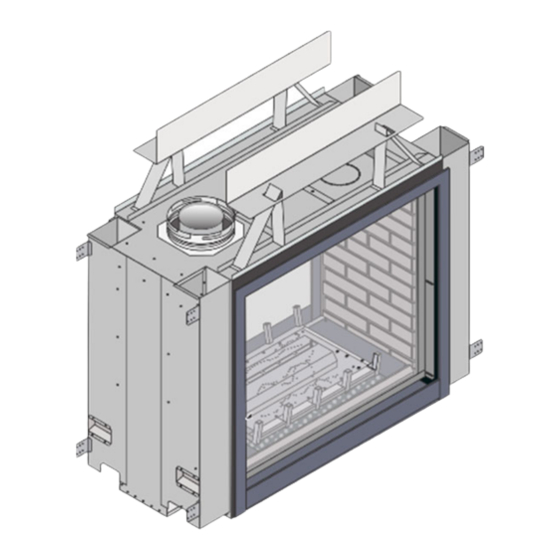
Introduction Overview This manual details the installation requirements for the PB36 See Through (ST) GSR2 fireplace. For operating and maintenance instructions, refer to the PB36 ST GSR2 Owner's Manual. Listing Details This appliance was listed to ANSI Z21.88. The listing label is attached to the appliance near the gas control valve. -
Page 3: Table Of Contents
Table of Contents Table of Contents Overview ..............2 Vent Configuration: Horizontal Termination ..29 Listing Details ............2 Vent Configuration: Vertical Termination ..30 Table of Contents ..........3 Masonry Chimney Conversions ......31 ... - Page 4 Safety Precautions Safety Warnings Failure to follow all of the requirements may result in property damage, bodily injury, or even death. Young children should be carefully supervised when they are in the same room as the appliance. Toddlers, young children, and others may be susceptible to accidental contact burns.
- Page 5 Safety Precautions Safety Warnings (continued) Because this heater can be controlled by a Instruct everyone in the house on how to thermostat there is a possibility of the heater shut gas off to the appliance and at the gas turning on and igniting any items placed on main shutoff valve.
-
Page 6: Installation Options
Features and Specifications Installation Options Residential or Mobile Home Internal or External Chase Raised or Floor Placement Horizontal or Vertical Vent Bedroom Approved Heating Specifications Natural Gas Propane Approximate Heating Capacity (in square feet) * Up to 1,800 Up to 1,800 Maximum BTU Input Per Hour (BTU/hr.) -
Page 7: Packing List
Installation for qualified installers only) Packing List LP (Propane) Conversion Kit: Outer Burner Orifice (1.25mm), Center Burner Orifice (1.25mm), Pilot Orifice (0.14 LP), Thimble (2-Piece Assembly) (2) Header Shields Optional Centering Brackets (see section “Centering the Fireplace”... -
Page 8: Massachusetts Requirements
Installation ( for qualified installers only) Massachusetts Requirements NOTE: The following requirements reference various Massachusetts and national codes not contained in this document. Requirements for the Commonwealth of Massachusetts For all side wall horizontally vented gas fueled equipment installed in every dwelling, building, or structure used in whole or in part for residential purposes, including those owned or operated by the Commonwealth and where the side wall exhaust vent termination is less than seven (7) feet above finished grade in the area of the venting, including but not limited to decks and porches, the following requirements shall be satisfied:... -
Page 9: Fireplace Placement Requirements
Installation for qualified installers only) Fireplace Placement Requirements The fireplace must be installed on a level surface capable of supporting the fireplace and vent. The fireplace must be placed directly on wood or a non-combustible surface (not on linoleum or carpet). ... -
Page 10: Televisions Placed Above The Fireplace
Installation ( for qualified installers only) Televisions Placed Above the Fireplace The following section gives guidelines to place a television above the fireplace. IMPORTANT NOTE REGARDING TELEVISIONS AND THIS FIREPLACE Most television manufacturers instruct the homeowner not to place the television above a heat source like this fireplace. Doing so may decrease the longevity of the television and negate the warranty. -
Page 11: Minimum Framing Dimensions - Top Or Side Vent Configuration
Installation for qualified installers only) Minimum Framing Dimensions – Top or Side Vent Configuration Min. Framing - Without CoolSmart TV kit WARNING When using a CoolSmart TV kit, see section: “CoolSmart TV - Framing the Chase” on page 70. Min Framing – With CoolSmart TV Kit When using a CoolSmart TV kit, see section: “CoolSmart TV - Framing the Chase”... -
Page 12: Header Standoff & Shield Installation
Installation ( for qualified installers only) Header Standoff & Shield Installation 1. The (4) header standoffs (2 on each side) are screwed down flat to the front edge of the top of the fireplace. Remove the screw that is closest to the center of the fireplace on each standoff. - Page 13 Installation for qualified installers only) 3. Set the header shield onto the standoffs with the 90° bend facing the middle of the fireplace. The tips of the standoffs will protrude through the heat shield. 4. Attach the heat shield to the standoffs by aligning the holes on the heat shield tabs with the holes in the header standoffs and secure using the included screws.
-
Page 14: Removing The Shipping Brackets
Installation ( for qualified installers only) Removing the Shipping Brackets Remove the shipping brackets from the lower middle of both ends of the fireplace. Use an 1/4” nut driver to remove the (2) bolts that secure the bracket to the side of the fireplace. -
Page 15: Installing The Optional Centering Brackets
Installation for qualified installers only) Installing the Optional Centering Brackets To install the optional centering brackets, follow the steps below. 1. If not already removed, remove the shipping Remove these bracket from the lower middle of the right side of bolts and discard the fireplace. -
Page 16: Nailing Brackets
Installation ( for qualified installers only) Nailing Brackets The fireplace has nailing brackets on both sides (the right side of the fireplace has them if the centering brackets are not used). Secure the fireplace to the framing with the nailing brackets. The nailing brackets should be oriented as shown below for all installs regardless of whether it is a flush installation or an extended installation. -
Page 17: Standard Vs Extended Position- Left Side
Installation for qualified installers only) Standard vs Extended Position– Left Side The left side of the fireplace has two movable panels with attached nailing brackets that act as support for the finish material. The nailing brackets have two positions: standard or extended. See the section “Facing Requirements”... -
Page 18: Standard Vs Extended Position- Right Side
Installation ( for qualified installers only) Standard vs Extended Position– Right Side There are nailing brackets attached to the body of the fireplace on the right side. If the optional centering brackets are not used position the nailing flanges as shown below, left. There are also nailing flanges on the optional centering brackets. -
Page 19: Standoff/Heatshield - Standard Vs. Extended Position
Installation for qualified installers only) Standoff/Heatshield - Standard vs. Extended Position There are two positions where the standoff/heat shield assembly can be installed. The standoffs are shipped in the standard (forward) position. If the unit is installed in the standard position no modification is needed. ... -
Page 20: Outdoor Fireplace Installations
Installation ( for qualified installers only) Outdoor Fireplace Installations Travis Industries Inc. gas-fired fireplaces are suitable for installation in outdoor areas protected from direct water impingement. In addition to maintaining listed mantel and combustibles clearances, a rain protection overhang factor of 1/2 shall be constructed to the front and to each side of installed appliances (see the illustration to the right). -
Page 21: Gas Line Requirements
Installation for qualified installers only) Gas Line Requirements MASSACHUSETTS INSTALLATIONS - WARNING: THIS PRODUCT MUST BE INSTALLED BY A LICENSED PLUMBER OR GAS FITTER WHEN INSTALLED WITHIN THE COMMONWEALTH OF MASSACHUSETTS. OTHER MASSACHUSETTS CODE REQUIREMENTS: The flexible connector must not be longer than 36 inches. ... -
Page 22: Gas Connection
Installation ( for qualified installers only) Gas Connection NOTE FOR RIGID PIPE: When using rigid pipe, you may wish to disconnect the shutoff valve from the fireplace and route the pipe through the fireplace wall. First, disconnect the gas line from the shutoff valve (see step 1 below). -
Page 23: Electrical Connection (Required)
Installation for qualified installers only) Electrical Connection (required) The electrical line to the grounded receptacle inside the fireplace must be installed by a qualified installer and must meet all local codes. Make sure the household breaker is shut off prior to working on any electrical lines. ... -
Page 24: Vent Requirements
Installation ( for qualified installers only) Vent Requirements The gas appliance and vent system must be vented directly to the outside of the building, and never be attached to a chimney serving a separate solid fuel or gas-burning appliance. Each direct vent gas appliance must use its own separate vent system. -
Page 25: Approved Vent
Installation for qualified installers only) Approved Vent Use 8" (203mm) or 6-5/8" (168mm) diameter DuraVent Direct-Vent Pro (or GS) *. If using 6-5/8" (168mm) diameter vent, attach the 8" (203mm) to the 6-5/8" (168mm) reducer (Travis part # 98900165) to the 8” starter collar. * Other vent may be approved with this fireplace. -
Page 26: Approved Vent Configurations
Installation ( for qualified installers only) Approved Vent Configurations Restrictor Position This appliance is equipped with an exhaust restrictor which is used to adjust the flow rate of intake air and exhaust gases. Depending upon the vent configuration, you may be required to adjust the restrictor position. -
Page 27: Diffuser Plate Adjustment
Installation for qualified installers only) Diffuser Plate Adjustment Certain vent configurations require the diffuser plate to be adjusted (refer to the approved vent configuration charts for details). See the directions below to change the diffuser position. © Travis Industries 1/12/2023 - 1556 PB 36CF ST Install... -
Page 28: Side Vent Configuration With Horizontal Termination (No Vertical Rise)
Installation ( for qualified installers only) Side Vent Configuration with Horizontal Termination (no vertical rise) The termination must fall within the shaded area shown in the chart. Use the indicated restrictor and diffuser positions. HINT: Travis Industries provides a minimum vent kit "H" (sku# 96200332). It includes a 90° Elbow, 3.9" (99mm) Section, 12”... -
Page 29: Vent Configuration: Horizontal Termination
Installation for qualified installers only) Vent Configuration: Horizontal Termination The termination must fall within the shaded area shown in the chart. Use the indicated restrictor and diffuser positions. 2’ vertical section required before first elbow. Up to four elbows (30°,45°, 60°, or 90°) may be used. ... -
Page 30: Vent Configuration: Vertical Termination
Installation ( for qualified installers only) Vent Configuration: Vertical Termination The termination must fall within the shaded area shown in the chart. Use the indicated restrictor and diffuser positions. Up to four elbows (30°,45°, 60°, or 90°) may be used. ... -
Page 31: Masonry Chimney Conversions
Installation for qualified installers only) Masonry Chimney Conversions This appliance may utilize 6-5/8" diameter direct vent manufactured by DuraVent (a reducer may be required). The vent may be adapted to utilize an existing masonry fireplace using the DuraVent Co-Linear Adapter (46DVA-GCL or 46DVA-CL34). -
Page 32: Class A Chimney Conversion
Installation ( for qualified installers only) Class A Chimney Conversion DuraVent provides a conversion kit for those wishing to use an existing class A chimney to vent this direct fireplace. The illustration below gives an overview of this type of installation. See the instructions included with the kit for details. ... -
Page 33: Termination Requirements
Installation for qualified installers only) Termination Requirements Venting terminals shall not be recessed into a wall or siding. Minimum 9" (229mm) clearance from any door or window Minimum 12" (305mm) above any grade, veranda, porch, deck, or balcony Minimum 1" (26mm) from outside corner walls NOTE: Clearance in accordance with local installation codes and the requirements of the gas supplier. -
Page 34: Hearth Requirements
Installation ( for qualified installers only) Hearth Requirements © Travis Industries 1/12/2023 - 1556 PB 36CF ST Install... -
Page 35: Facing Requirements
Installation for qualified installers only) Facing Requirements Non-combustible facing must extend from 1” above the base of the fireplace to the framing header (see illustration below for details). Non-combustible facing must extend the entire width of the unit to the framing opening on both sides (see illustration below for details). -
Page 36: Standard Vs. Extended Position
Installation ( for qualified installers only) Standard vs. Extended Position The nailing brackets on the side of the fireplace may be placed in the standard or extended position to best suit the facing being used (the header shield is also moved). Most installations use the standard nailing bracket position. -
Page 37: Thick Facing Guide
Installation for qualified installers only) Thick Facing Guide The thick facing guide is shipped pre-attached to the fireplace. - Thick Facing - If using thick facing, leave the guide in place (see “Thick Facing” on the following page). - Thin Facing - If using thin facing, you may remove the thick facing guide following the directions below (see “Thin Facing”... -
Page 38: Thick Facing (Facing Thicker Than 1-1/2")
Installation ( for qualified installers only) Thick Facing (Facing Thicker than 1-1/2”) If using thick facing, make sure to leave the thick facing guide in place. Make sure to leave the screen assembly in the stock (fully in) position. You may leave the screen assembly in place while installing thick facing. You may wish to protect it with plastic (or other suitable material) to repel debris. -
Page 39: Thick Facing Guide Size
Installation for qualified installers only) THICK FACING GUIDE SIZE Tile Stop Tile Stop Width (a) Height (b) PB36CF ST 35-1/8” (893mm) 32-5/8” (829mm) © Travis Industries 1/12/2023 - 1556 PB 36CF ST Install... -
Page 40: Thin Facing (1/2" To 1-1/2")
Installation ( for qualified installers only) Thin Facing (1/2” to 1-1/2”) When using thin facing you may remove the thick facing guide and tuck the facing underneath the screen assembly. The screen assembly mounts may be adjusted to position the screen assembly directly against the facing (see “Screen Assembly Mounts”... -
Page 41: Mantel Requirements
Installation for qualified installers only) Mantel Requirements Use the table below to determine the maximum mantel depth allowed. The mantel depth (measured from the non-combustible facing) must fall within the shaded portion of the table. Any material above the fireplace that protrudes more than 3/4” (19mm) from the non-combustible facing is considered a mantel and must meet the mantel requirements. -
Page 42: Mantel Clearances
Installation ( for qualified installers only) Use of a Non-Combustible Mantel Below Listed Mantel Clearances Each gas fireplace has a unique set of mantel requirements. If you wish to place a non-combustible mantel at a lesser height than specified in this manual, it will need to meet the following requirements: ... -
Page 43: Finalizing The Installation
Finalizing the Installation for qualified installers only) Finalizing the Installation 1. Remove the glass (see page 47). NOTE: If using propane (LP) convert the appliance prior to installing the media. 2. We recommend you purge the gas line at this time (with the glass removed). This allows gas to be detected once it enters the firebox, ensuring gas does not build up. -
Page 44: Air Shutter Adjustment
Finalizing the Installation (for qualified installers only) Air Shutter Adjustment Let the heater burn for fifteen minutes (make sure the logs and glass are in place). The flames should be yellow with no sooting. Adjust the air shutter, if necessary, to achieve the correct looking flame. Air Shutter Adjustment Adjust the flame to its highest position - the flames should not contact the top of the firebox. -
Page 45: Location Of Controls
Finalizing the Installation for qualified installers only) Location of Controls There is a door on the lower portion of the screen assembly to provide access to the manual controls on the fireplace. The door is held closed by two magnets. Open the door by gently pulling outward on the upper portion of the lower trim. -
Page 46: Pilot Fuel Conservation Timer (Gsb & Gsr Units)
Finalizing the Installation (for qualified installers only) Pilot Fuel Conservation Timer (GSB & GSR units) 7 Day Pilot Shutoff Timer (applies to units in CPI mode only) This appliance may be equipped with a 7-day pilot shutoff timer. This timer helps conserve fuel and save money by turning the pilot off when the appliance is not used for 7 days (this timer is mandated in certain areas for conservation purposes). -
Page 47: Glass Frame Removal And Installation
Finalizing the Installation for qualified installers only) Glass Frame Removal and Installation A barrier designed to reduce the risk of burns from the hot viewing glass is provided with this appliance and shall be installed for the protection of children and other at-risk individuals. If the barrier becomes damaged, the barrier shall be replaced with the manufacturer’s barrier for this appliance. - Page 48 Finalizing the Installation (for qualified installers only) 2. Remove the glass frame following the directions below. Replacement Glass Frame Part # 36 CF ProBuilder 250-04837 © Travis Industries 1/12/2023 - 1556 PB 36CF ST Install...
-
Page 49: Barrier Screen Visual Deflector Adjustment
Finalizing the Installation for qualified installers only) The latch can come loose from the glass frame anchor. This occurs when it is turned 1/4 turn when it is disengaged. Follow the directions below to re-install the latch if it becomes loose. Barrier Screen Visual Deflector Adjustment The barrier screen assembly has an adjustable visual deflector along the lower edge. -
Page 50: Log Set Installation
Finalizing the Installation (for qualified installers only) Log Set Installation Part Numbers / Compatibility Classic Oak - sku# 94500642 Birch - sku# 94500641 Installation Warnings NOTE: Consult the installation manual for the order of installation. If using propane (LP), convert the appliance before installing the log set. -
Page 51: Log Set Overview - Classic Oak 94500642
Finalizing the Installation for qualified installers only) Log Set Overview – Classic Oak 94500642 When installed, the ten (10) logs should appear as shown below. Service Side View Log #10 Log #1 Log #8 Log #3 Log #7 Log #2 Log #5 Log #9 Log #6... -
Page 52: Log Set Overview - Birch 94500641
Finalizing the Installation (for qualified installers only) Log Set Overview – Birch 94500641 When installed, the ten (10) logs should appear as shown below. Service Side View Log #10 Log #1 Log #3 Log #8 Log #7 Log #2 Log #5 Log #9 Log #6 Log #4... -
Page 53: Installation
Finalizing the Installation for qualified installers only) Installation Log #1 Install Log #1 as shown below. Log #1 has holes on the bottom that rest over two pins in the middle of the burner (see photos below). This log is directional, and the side shown in the left-top picture below must be facing the service side of the fireplace. - Page 54 Finalizing the Installation (for qualified installers only) Log #2 Log #2 has a flat surface on the bottom right branch of the log. The flat surface rests on the firebox floor to the right of the log grate. The left rear of log #2 has a cut-out that rests against the sloped section of the center burner.
- Page 55 Finalizing the Installation for qualified installers only) Log # 4 Install log #4 as shown below. The cut branch on the bottom left of Log #4 rests on the media tray to the left of the log grate. There are notches on the front of the log that fit around the two left log grate fingers. With the log in place, pull it forward as far as it will go and check to make sure the log does not obstruct any burner holes.
- Page 56 Finalizing the Installation (for qualified installers only) Log # 6 Install log #6 as shown below. The hole in the bottom of log #6 rests on the left log locating pin and sits in the diagonal groove on the top of log #4. The wider end of log #6 should be on the left and the sharper, charred end points up and right.
- Page 57 Finalizing the Installation for qualified installers only) Log # 8 Install log #8 as shown below. The hole on the bottom of the narrow, charred end of log #8 rests on the log locating pin on the right end of log #1. The wider end of log #8 rests on log #2 as shown below. NOTE: The red line in the lower left picture represents the direction the log should be resting.
- Page 58 Finalizing the Installation (for qualified installers only) Log # 10 Install log #10 as shown below. The hole on the bottom of log #10 rests over the pin on the left end of log #1. The right end of the log rests on top of log #9 and the crook of the log fits around the center log grate finger.
- Page 59 Finalizing the Installation for qualified installers only) (94500641) Birch - Log Replacement Part Numbers (94500642) Oak - Log Replacement Part Numbers Log # Qty. Part # Image Log # Qty. Part # Image Log #1 250-06036 Log #1 250-06026 Log #2 250-06037 Log #2 250-06027...
-
Page 60: Ember Bed Glass And Ember Material Installation
Finalizing the Installation (for qualified installers only) Ember bed Glass and Ember Material Installation Ember bed Glass Installation Make sure the ember skirt is in place. The skirt hooks over the front of the ember platform and slopes outward toward the glass. The skirt helps keep the glass and ember material from falling off the platform when the glass is removed. -
Page 61: Ember Material Installation (Gsr2 Only)
Finalizing the Installation for qualified installers only) Ember Material Installation (GSR2 ONLY) Once the ember glass installation is complete, place a generous amount of ember material on the firebox floor on either side of the firebox. Completely cover any visible metal on the firebox floor. NOTE: Make sure no ember material is placed directly on the burner. -
Page 62: Lp Conversion Instructions
Finalizing the Installation (for qualified installers only) LP Conversion Instructions WARNING This conversion kit shall be installed by a qualified service agency in accordance with the manufacturer’s instructions and all applicable codes and requirements of the authority having jurisdiction. If the information in these instructions is not followed exactly, a fire, explosion, or production of carbon monoxide may result causing property damage, personal injury, or loss of life. - Page 63 Finalizing the Installation for qualified installers only) Remove the manifold covers. NOTE: Discard the orifice gaskets and reinstall the manifold covers after changing the orifices Orifice gaskets Manifold Covers 3. Follow the directions below to replace the orifice. PB36CF ST Orifice Numbers Center 1.25mm Outer...
- Page 64 Finalizing the Installation (for qualified installers only) 4. Install the LP pilot orifice following the instructions below. (a) Use a 7/16” open-end wrench to remove the pilot hood. (b) Remove and discard the Natural Gas (NG) orifice. Place the LP orifice in the pilot assembly then replace the pilot hood, tightening the pilot hood until it is snug (do not over-tighten).
-
Page 65: Fireback Installation
Optional Equipment for qualified installers only) Fireback Installation SKU #'s Black Glass - sku# 96100857 Brick - sku# 96100858 Compatibility Packing List ProBuilder 36 Clean Face See-Through Fireplace (2) Side Fireback (4) Spacer Clips (GLASS FIREBACK ONLY) CERAMIC FIREBACKS ARE FRAGILE HANDLING THE FIREBACKS: The firebacks are fragile –... -
Page 66: Installation
Optional Equipment (for qualified installers only) Installation WARNING Turn off the gas to the appliance and make sure it has fully cooled prior to conducting service. 1. Remove the glass frame (both sides) and packaged logs (see the installation manual for details). 2. - Page 67 Optional Equipment for qualified installers only) NOTE: The brick fireback panels have a top and a bottom. The bottom corners are notched. Make sure the panels are properly oriented before trying to place them in the fireplace. 4. Tilt one of the side firebacks and place it inside the fireplace. Set the bottom edge of the fireback panel up against the bottom of the side wall of the firebox (there is a channel on the floor of the firebox that the fireback sets in).
-
Page 68: Coolsmart Tv - Installation Overview (Optional)68
Optional Equipment (for qualified installers only) CoolSmart TV – Installation Overview (Optional) The CoolSmart system is designed to redirect the convective heat of the fireplaces from the front of the unit, just above the glass, to a location higher on the wall. The use of this kit allows for reduced clearances to televisions and a recessed cavity above the fireplace. -
Page 69: Pb 36Cf St - Installation Requirements
Optional Equipment for qualified installers only) PB 36CF ST - Installation Requirements © Travis Industries 1/12/2023 - 1556 PB 36CF ST Install... -
Page 70: Pb 36Cf St - Framing The Chase
Optional Equipment (for qualified installers only) PB 36CF ST - Framing the Chase When using this kit, disregard the framing dimensions in the manual and follow the framing instructions shown below*. © Travis Industries 1/12/2023 - 1556 PB 36CF ST Install... -
Page 71: Pb 36Cf St - Fireplace Preparation
Optional Equipment for qualified installers only) PB 36CF ST - Fireplace Preparation WARNING: You must remove (3) layers of cover plates for each of the flex attachment points to extract the heat properly from around the firebox. Not removing all the cover plates can create hazardous conditions. - Page 72 Optional Equipment (for qualified installers only) Insert a starter collar into each of the (2) holes that were uncovered in the previous step and bend the tabs to secure the starter collar to the fireplace. Seal the joints with silicone caulk or aluminum (U.L.
-
Page 73: Pb 36Cf St- Reduced Mantel Height
Optional Equipment for qualified installers only) PB 36CF ST- Reduced Mantel Height When using this kit, disregard the combustible mantel requirements in the manual and follow the requirements shown to the right. If you wish to place a TV above the mantel, it must meet the following requirements: ... -
Page 74: Wiring Diagram
Optional Equipment (for qualified installers only) Wiring Diagram © Travis Industries 1/12/2023 - 1556 PB 36CF ST Install... - Page 75 Notes © Travis Industries 1/12/2023 - 1556 PB 36CF ST Install...
-
Page 76: Index
Index Index Additional Items Required ........7 LP Conversion Instructions ......62 Air Shutter Adjustment ........44 Mantel Column Clearances ......41 Altitude Considerations ........24 Mantel Requirements ........41 Approved Termination ........24 Masonry Chimney Conversions ....... 31 Approved Vent ..........24 Massachusetts Requirements ......