Barco UDM 4K15 User Manual
Hide thumbs
Also See for UDM 4K15:
- User manual (210 pages) ,
- Installation manual (106 pages) ,
- User manual (190 pages)
Table of Contents
Advertisement
Quick Links
Advertisement
Table of Contents

Related Manuals for Barco UDM 4K15


Summary of Contents for Barco UDM 4K15
- Page 1 User manual ENABLING BRIGHT OUTCOMES...
- Page 2 Product revision Software Revision: 2.2 Barco Fredrikstad AS Habornveien 53, N-1630 Gamle Fredrikstad, Norway Support.fre@barco.com www.barco.com Barco NV Beneluxpark 21, 8500 Kortrijk, Belgium www.barco.com/en/support www.barco.com...
- Page 3 Barco. If the purchaser or a third party carries out modifications or repairs on goods delivered by Barco, or if the goods are handled incorrectly, in particular if the systems are operated incorrectly or if, after the transfer of risks, the goods are subject to influences not agreed upon in the contract, all guarantee claims of the purchaser will be rendered invalid.
- Page 4 Disclaimer for camera usage Barco provides a kit with a laser range finder and USB camera to help measure the distance from the front of the projector to the projected surface and to help monitor the performance of the projector. Barco disclaims any liability for any use of the USB camera outside this intended use.
-
Page 5: Table Of Contents
Table of contents 1 Safety information....................................9 General Considerations ................................10 Important safety instructions..............................11 Product safety labels..................................15 High Brightness precautions: Hazard Distance ......................16 HD for fully enclosed projection systems...........................18 HD in function of modifying optics ............................19 Radio equipment (optional) ...............................20 Compliance ......................................20 Download Product Manual ................................20 2 Getting Started......................................21... - Page 6 Pulse Quad Combo input Mk II ...............................43 Pulse Quad Combo input Mk I..............................44 Pulse Quad DP 1.2 input ................................45 Pulse SFP input ....................................46 5 GUI – Introduction....................................47 Overview......................................48 Navigation ......................................51 Test Patterns......................................53 6 GUI – Source ......................................55 Displaying a single source .................................56 Displaying multiple sources: Stitched layouts.........................56 Connector Settings ..................................58 7 GUI –...
- Page 7 8.14.3 Connection possibilities............................112 8.14.4 3D Setup ..................................113 9 GUI – Profiles ......................................115 Profiles introduction ..................................116 Profiles setup parameters ................................116 Saving settings to a new profile ............................117 Deleting a projector profile...............................119 10 GUI – System Settings................................. 121 10.1 Remote control ....................................122 10.1.1 Broadcast address ..............................
- Page 8 13.2 Cleaning the lens ..................................171 13.3 Cleaning the exterior of the projector..........................172 13.4 Cleaning / replace the air filters............................172 A Specifications ......................................177 Specifications SDI inputs................................. 178 Specifications HDMI inputs ..............................178 Specifications HDBaseT inputs............................179 Specifications DisplayPort 1.2 inputs ..........................180 Specifications SFP inputs ...............................
-
Page 9: Safety Information
Ensure that you understand and follow all safety guidelines, safety instructions and warnings mentioned in this chapter before installing the UDM projector. Clarification of the term “UDM” used in this document When referring in this document to the term “UDM” means that the content is applicable for following Barco products: •... -
Page 10: General Considerations
• Before operating this equipment please read this manual thoroughly and retain it for future reference. • Installation and preliminary adjustments must be performed by qualified Barco personnel or by authorized Barco service dealers. • All warnings on the projector and in the documentation manuals must be adhered to. -
Page 11: Important Safety Instructions
See the product safety manual for details. Users definition Throughout this manual, the term SERVICE PERSONNEL refers to Barco authorized persons having appropriate technical training and experience necessary to be knowledgeable of potential hazards to which they are exposed (including, but not limited to HIGH VOLTAGE ELECTRIC and ELECTRONIC CIRCUITRY and HIGH BRIGHTNESS PROJECTORS) in performing a task, and of measures to minimize the potential risk to themselves or other persons. - Page 12 This product contains no user serviceable parts. Attempts to modify/replace mechanics or electronics inside the housing or compartments will violate any warranties and may be hazardous. This kind of operations shall only be performed by Barco authorized service personnel. •...
- Page 13 • Max units in hanging configuration, 2 units. • When hanging projectors on a truss with the Barco stacking frame, always secure the stack with safety cables between the projectors and the truss. • When using the projector in a hanging configuration, always mount 2 safety cables. See installation manual for the correct use of these cables.
- Page 14 For lens cleaning follow the instructions precisely as stipulated in the projector manual. • Only use zoom lenses of the Barco TLD+ series on the 4K models of the projector. Using other lenses will damage the internal optics. For suitable fixed TLD+ lenses contact Barco or see Barco website.
-
Page 15: Product Safety Labels
Use an appropriate forklift to raise flight cases and take the necessary precautions to avoid personnel injury. Safety Data Sheets for Hazardous Chemicals For safe handling information on chemical products, consult the Safety Data Sheet (SDS). SDSs are available upon request via safetydatasheets@barco.com. 1.3 Product safety labels Light beam related safety labels Label image... -
Page 16: High Brightness Precautions: Hazard Distance
Safety information Label image Label description Label location Hazard class 2: laser radiation warning symbol. 0.95 mW - 638 nm. WARNING! DO NOT LOOK INTO THE BEAM NO DIRECT EYE EXPOSURE TO THE PROJECTOR BEAM IS PERMITTED LASER RADIATION - DO NOT STARE INTO LASER RANGING BEAM RG3 IEC EN 62471-5:2015 CLASS 2 IEC EN 60825-1:2014 HAZARD DISTANCE: CONSULT SAFETY MANUAL... - Page 17 Safety information For example, projectors that have a HD greater than 1 m and emit light into an uncontrolled area where persons may be present should be positioned in accordance with “the fixed projector installation” parameters, resulting in a HD that does not extend into the audience area unless the beam is at least 2.0 meter above the floor level.
-
Page 18: Hd For Fully Enclosed Projection Systems
The LIP shall be installed by Barco or by a trained and Barco-authorized installer or shall only be transferred to laser light show variance holders. This is applicable for dealers and distributors since they may need to install the LIP (demo install) and/or they transfer (sell, rent, lease) the LIP. -
Page 19: Hd In Function Of Modifying Optics
Safety information Restricted Access location (enclosed projection area). Restriction Zone. Projector. Projection Distance. Theater (observation area). Separation Width. Must be minimum 1 meter. For this type of setup 3 different HD shall be considered: • HD as discussed in “High Brightness precautions: Hazard Distance”, page 16, relevant for intrabeam exposure. -
Page 20: Radio Equipment (Optional)
NO PL 5250 MHz frequency range. UKNI Hereby, Barco declares that the radio equipment type UDM is in compliance with Directive 2014/53/EU. The full text of the EU declaration of conformity is available at the following internet address: https://www. barco. -
Page 21: Getting Started
Getting Started Getting to know the projector ......................22 Power on the projector ........................24 Start image projection ........................25 Switching to ready mode .......................28 Power off projector........................28 About this chapter This chapter and by extension this whole document, the user manual, is intended for the user who want’s to operate the projector. -
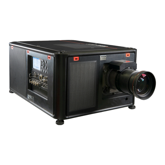
Page 22: Getting To Know The Projector
Getting Started 2.1 Getting to know the projector Orientation convention This manual refers to the left side of the projector as the side at your left hand when standing behind the projector and looking at the projection screen in front of the projector. Image 2–1 Right Left... - Page 23 Getting Started 9 10 11 Image 2–3 IR receiver projector rear side Overvoltage status light Mains power input socket (for C19 plug) USB port (to control motorized rigging frame) Power ON/OFF switch For detailed info about the Input & Communication module see chapter “Input &...
-
Page 24: Power On The Projector
Getting Started Image 2–4 CAUTION: Keep the air inlets and outlet at all times free. Make sure there is a minimum distance of 40 cm (15.7 in) between the air outlet and the nearest solid object. Projector Infra Red receivers and Remote Controle Unit The projector has three Infra Red receivers: one at the rear (next to the power input), one at the front (below the lens holder) and one at the right side (integrated in the Input &... -
Page 25: Start Image Projection
Getting Started Warning: Never switch on the projector if the OVERVOLTAGE status light lit up. Neglecting will cause irreversible damage to the projector. ► If no, proceed with the next step. Press the mains switch (reference 2) to switch on this projector. Image 2–6 •... - Page 26 Getting Started Image 2–9 Example of connecting an HDMI source. Check if the SYNC LED lit up ORANGE (reference 1). This indicates that the sync is detected on the input signal. Image 2–10 Select the source Press the Input button (reference I ) on the remote control or local keypad. Image 2–11 The Source selection menu opens on the LCD display.
- Page 27 Getting Started Image 2–12 Example of the input selection menu Use the arrow keys to select the desired source. • the SEL LED (reference 2) of the selected source lit up GREEN, and • the image of the selected source is projected. Image 2–13 Quick test pattern selection Press the Test pattern button (references P) on the remote control or local keypad.
-
Page 28: Switching To Ready Mode
Getting Started 2.4 Switching to ready mode How to switch to ready mode Press and hold the Power on/off button for 3 seconds on the local keypad, or press the Power Off button on the remote control. The projector goes to Ready mode. The after-cooling cycle will start (about 30 seconds). During this period the Power on/off button will blink. -
Page 29: Pulse Remote Control Unit
Pulse Remote Control Unit Pulse RCU, battery installation ......................30 Pulse RCU, protocol setup ......................31 Pulse RCU, function of the on/off button ..................31 Using the RCU ..........................32 Pulse RCU, Functionality overview ....................33 Pulse RCU, function of the “button pressed indicator” ..............33 Pulse RCU, function of the “RGB filter”... -
Page 30: Pulse Rcu, Battery Installation
Pulse Remote Control Unit 3.1 Pulse RCU, battery installation Where to find the batteries for the remote control ? The batteries are not placed in the remote control unit to avoid control operation in its package, resulting in a shorter battery life time. At delivery the batteries can be found in a separated bag attached to the remote control unit. -
Page 31: Pulse Rcu, Protocol Setup
Depending on the projector to control the remote control can be switched between these protocols. Which protocol to use • The NEC protocol has to be used for Barco projectors based on the Pulse platform: F70, F80, F90, HDX 4K, UDX, UDM, XDL, etc. •... -
Page 32: Using The Rcu
Using the RCU in combination with a 3D emitter When using a 3D emitter that radiates IR beams (e. g. the optional 3D emitter that Barco provides), the IR beams of the 3D emitter may interfere with the IR communication between projector and the RCU. -
Page 33: Pulse Rcu, Functionality Overview
Pulse Remote Control Unit 3.5 Pulse RCU, Functionality overview Remote Control Unit buttons Image 3–7 Button pressed indicator Backspace (while entering values) Shutter open XLR connector Shutter close Decimal mark (while entering values) LCD panel on / off Macro button Project OSD on / off Menu back Lens zoom... -
Page 34: Pulse Rcu, Function Of The "Rgb Filter" Button
Pulse Remote Control Unit 3.7 Pulse RCU, function of the “RGB filter” button Filtering the color of the projected image By pressing the RGB filter button on the RCU you can place a color filter on the output of the projector. This feature can be useful during the installation and configuration of a multi-projector or multi-channel setup. -
Page 35: Using The Mini-Jack Connector Of The Rcu
(optional) Introduction Barco offers a silicone form fitting protection sleeve for the Pulse RCU. The silicone material keeps it comfortably, non slip and soft touch. All buttons and holes remain accessible. The sleeve is quick and easy installed. For ordering information see Barco website. - Page 36 Pulse Remote Control Unit How to install Pull off the rubber XLR-lid from the RCU. Image 3–10 Place back side (XLR side) of the RCU into the sleeve and pull the other side of the sleeve over the front side of the RCU. Image 3–11 R5911443 /08...
-
Page 37: Input & Communication
Input & Communication Introduction ..........................38 Local Keypad and LCD panel ......................38 LCD touch panel...........................39 Communication connections......................40 LED and Button indication chart.....................42 Pulse Quad Combo input Mk II ......................43 Pulse Quad Combo input Mk I .......................44 Pulse Quad DP 1.2 input .......................45 Pulse SFP input..........................46 R5911443 /08... -
Page 38: Introduction
Input & Communication 4.1 Introduction General The Input & Communication module consists of a local keypad with LCD panel (1), a communication panel (4) and a Quad Combo input board (5). The free input slot can be used for optional modules (e.g. the Quad DP 1.2 input board). -
Page 39: Lcd Touch Panel
Input & Communication Menu navigation Input selection Menu confirmation, OK button Shutter open / close Menu open / close Test patterns Menu back Lens adjustment Power on / off LCD panel Project OSD on / off Local Keypad The Keypad gives direct access to several functions, in addition to access to the menu system. The keypad has a backlight that can be switched on and off manually. -
Page 40: Communication Connections
Input & Communication 4.4 Communication connections Communication Panel 12V 1A Image 4–3 WIFI antenna for wireless IP (optional) RS232 for serial communication 12V 1A output Sync Out 3D Firmware update / USB download log files Sync In 3D 10/100 base-T for external control over IP and Art-Net Status lights DMX interface input IR receive sensor... - Page 41 Input & Communication Advantages of using RS232/RS422 serial communication: • easy adjustment of the projector via PC (or MAC). • allow storage of multiple projector configurations and set ups. • wide range of control possibilities. • address range from 0 to 255. •...
-
Page 42: Led And Button Indication Chart
Input & Communication 4.5 LED and Button indication chart Button Backlight Status Description Button Color status Power button Blinking WHITE (slow) Projector starts up (booting) Blinking WHITE (fast) Firmware upgrade Solid WHITE Projector is in Standby or Ready mode Blinking BLUE Projector goes to ON mode Solid BLUE Projector is ON... -
Page 43: Pulse Quad Combo Input Mk Ii
Input & Communication 4.6 Pulse Quad Combo input Mk II Overview Quad Combo Input Mk II Image 4–4 Quad SDI channel A: 3G/12G input DisplayPort Input Quad SDI channel B: 3G input HDMI input Quad SDI channel C: 3G SDI input + 3G/12G output HDBaseT input 1 Quad SDI channel D: 3G SDI input / output HDBaseT input 2... -
Page 44: Pulse Quad Combo Input Mk I
Input & Communication HD, 3G & 12G IN 0 OUT 0 IN 1 OUT 1 N.C. HD & 3G IN 0 OUT 0 N.C. IN 1 OUT 1 FPGA IN: HD & 3G SDI IN/OUT OUT 0 OUT: HD, 3G & 12G IN 0 N.C. -
Page 45: Pulse Quad Dp 1.2 Input
Input & Communication Remark concerning the Mk I and Mk II inputs boards The Mk I input board miss functionality that has been implemented on the Mk II input board. These missing features include: • Loop-through functionality • 12G SDI support •... -
Page 46: Pulse Sfp Input
Input & Communication 4.9 Pulse SFP input The Barco SFP Input Board has been designed and tested to work alongside the Barco SFP Output Board. However, it is possible that the SFP Input board can also work with other third-party devices that support 12G over fiber. -
Page 47: Gui - Introduction
GUI – Introduction Overview .............................48 Navigation............................51 Test Patterns ..........................53 About this chapter This chapter gives an general overview of the Graphic User Interface. R5911443 /08... -
Page 48: Overview
GUI – Introduction 5.1 Overview Disclaimer on GUI images used in this manual The GUI images in this manual are example illustrations and should be treated as such. While the name of the projector displayed in the illustrations may be different from the projector model you are currently using, the menu lay-out and functionality is identical. - Page 49 GUI – Introduction Image 5–2 Example of the Product registration form GUI – Status Screens While the projector menu is not active, or the projector is Ready or Standby mode, the Status screens remain visible. These screens give an overview of the state of the projector and can be navigated through using the left and right arrow keys, or by swiping the screen left or right.
- Page 50 GUI – Introduction The OSD can be disabled by pressing the OSD on/off button. Image 5–4 Example of the home menu The projector software platform uses access levels what each user can do. A standard user has access to the standard projector functionality.
-
Page 51: Navigation
GUI – Introduction GUI – Pulse software menu tree Source Image Installation Pro les Settings Test patterns Status Lx Quad combo Pro le Edit Product Status screen Contrast Laser ranging Test pattern x registration Connector x New Pro le Custom test About Date and time Motorized frame... - Page 52 GUI – Introduction Image 5–6 To start up the menu structure, press MENU (1). Use the arrow keys (Menu Navigation buttons) to navigate to the desired menu item (2). The background color changes to light blue. Press the Menu Selection button (center key of the arrow keys), also called OK button, to activate that item and to jump one level deeper (3).
-
Page 53: Test Patterns
GUI – Introduction To enter values with the local keyboard, use the arrow keys to select the first digit, press OK. Select the second digit and press OK. Continue until all digits are entered. Close the action by selecting the enter (↵) button and press OK. - Page 54 GUI – Introduction Example of test Type Explanation pattern icon Standard Standard test patterns. See previous list to see all test patterns test available for your device. patterns Warped test Available from software 2.2 onward. Every test pattern will have a patterns “warped”...
-
Page 55: Gui - Source
GUI – Source Displaying a single source ......................56 Displaying multiple sources: Stitched layouts ..................56 Connector Settings ........................58 About the Source menu This menu is used to select, review and configure sources into the projector. R5911443 /08... -
Page 56: Displaying A Single Source
GUI – Source 6.1 Displaying a single source About selecting a source Before a source can be projected, the source signal must be connected to the source input(s) of the device and a valid synchronization signal must be available along with the source signal on at least one of the input connectors. - Page 57 GUI – Source The table below describes the different Stitch Layouts and scan directions. Type of layout Description Available connectors Mode A single source is displayed in Quad Combo input: Mono / Active full screen stereo • SDI (4x) • HDBaseT (2x) •...
-
Page 58: Connector Settings
GUI – Source Image 6–4 Example of the stitched layout options Select the desired stitched input. Tip: If the Quad DP input board is installed, scroll all the way down the menu for the stitched options on that board. Image 6–5 Example of the stitched input options with the Quad DP board installed 6.3 Connector Settings About Connector Settings The Connector Settings menu allows you to change settings for each input connector of the projector. - Page 59 GUI – Source Image 6–6 Main menu, Source Press OK. The Select Source menu is displayed with the actual available sources filled out. Scroll down to the bottom of the list of available sources and select Connector Settings. Image 6–7 Source menu, connector settings The available input connectors are displayed.
- Page 60 GUI – Source You can change the following: • To force a limit on the used signal range, select one of the available signal ranges. • To force a limit on the color space, select one of the available color spaces. •...
-
Page 61: Gui - Image
GUI – Image Setting image levels manually......................62 Adjusting the sharpness ........................63 Adjusting the gamma correction.....................64 Setting the desired Gamma type ....................65 Digital Shift & Zoom ........................67 RealColor P7..........................71 Displaying HDR content ........................73 Dynamic contrast..........................74 R5911443 /08... -
Page 62: Setting Image Levels Manually
GUI – Image 7.1 Setting image levels manually Purpose Contrast: Change the contrast of the complete output signal of the projected image. Brightness: Change the brightness of the complete output signal of the projected image. Saturation: Change the saturation of the complete output signal of the projected image. How to set up Contrast In the main menu, select Image →... -
Page 63: Adjusting The Sharpness
GUI – Image Image 7–4 Example of the image sliders, brightness is the second slider If necessary, use the ▲ or ▼ key to select the other image adjustment options. How to set up Saturation Level In the main menu, select Image → Saturation. Image 7–5 Image menu —... -
Page 64: Adjusting The Gamma Correction
GUI – Image Increasing the sharpness will have the best effect in high contrast images, eg a table with text and borders. In a natural picture, high sharpness can be perceived as noise, as all details in the picture will be amplified. Available range: -2 to 8. -
Page 65: Setting The Desired Gamma Type
GUI – Image Image 7–10 Image menu – Gamma Use the ▼ key to select the slider. Use the ◄ or ► key to change the gamma value between 1.0 and 2.8 . The default value is 2,2. Tip: The slider can be adjusted with a precision of 0.1. Image 7–11 Example of the gamma menu 7.4 Setting the desired Gamma type About the alternate gamma types... - Page 66 GUI – Image If the source signal is HDR encoded an HDR icon will be visible next to the source signal. This is visible both in the Source selection menu, as well as the status menu. Image 7–12 Example of the HDR icon on the status menu For more info on PQ and HDR, refer to “Displaying HDR content”, page How to adjust the gamma type?
-
Page 67: Digital Shift & Zoom
GUI – Image Image 7–15 Example of selecting a gamma type Tip: If not sure what gamma type to select, keep the default value auto selected. This automatic mode will determine the used gamma type based on the incoming signal. However: keep in mind when using the automatic mode, your media player needs to be configured correctly as well. - Page 68 GUI – Image Image 7–16 Originally picture, not digitally zoomed Image 7–17 Picture digitally zoomed in Image 7–18 Picture digitally zoomed out The effect of Digital Shift This function will shift the picture digitally, meaning that the picture will be moved in any direction. As a result, some parts of the picture might be shifted outside the DMD range.
- Page 69 GUI – Image Image 7–19 Original Picture, not digitally shifted Image 7–20 Picture shifted horizontally Image 7–21 Picture shifted vertically Digital Shift & Zoom In the main menu, select Image → Digital Zoom Shift. Image 7–22 Image menu, digital zoom and shift The Digital Zoom Shift menu is displayed.
- Page 70 GUI – Image Image 7–23 Example of the digital zoom and shift menu In order to optimize the digital zoom, enable the Zoom slider. In order to optimize the digital shift, enable the Shift slider. When one or both of the modes are enabled, use the arrow keys to select the mini-keypad in this menu. Use the enter key to activate this mini-keypad.
-
Page 71: Realcolor P7
GUI – Image • Use the ▲ or ▼ key to shift the lens (image) in vertical direction. • Use the enter key to transform the keypad to digital zoom mode (if enabled). • Use the return key to exit without saving. If digital zoom is enabled, you can now do the following: •... - Page 72 GUI – Image • Temperature: Configure the white point via a color temperature slider. The white point is specified on a Kelvin scale between 3200K and 13000K tracking along the black body curve. Define the coordinates for each available color. Click on a coordinate value and select the current value.
-
Page 73: Displaying Hdr Content
GUI – Image Image 7–30 Example of one of the presets, here DCI-P3 Note: After choosing one of the presets, you can still alter the values of the coordinates to your own choosing, similarly to how you set custom P7 values. Use the Reset icon to return to the default values of the chosen preset. -
Page 74: Dynamic Contrast
GUI – Image The projected HDR content depends on the following factors: • Mastering luminance: This is content-specific and cannot be changed. • Screen luminance: Every projection screen has a specific luminance (measured in nits or foot-Lambert). Entering this luminance in the projector will adapt the content towards the intended HDR result. •... - Page 75 GUI – Image How to set the dynamic contrast? In the main menu, select Image → Advanced → DynaBlack. Image 7–34 The DynaBlack menu is displayed. Image 7–35 Example of the DynaBlack menu Select the desired dynamic contrast setting, or leave the default on (medium). The result will slowly become visible.
- Page 76 GUI – Image R5911443 /08...
-
Page 77: Gui - Installation
GUI – Installation Configuring the lens, optical zoom-focus ..................78 Configuring the lens, shift ......................78 Configuring the lens, dynamic focus ....................79 Configuring the lens, Shift to center....................80 Configuring the lens, tilt sensor ......................81 Laser ranging ..........................82 Manipulating the rigging frame ......................83 Manipulating the rigging frame, center position ................85 Orientation ...........................85 8.10 Scaling modes..........................86... -
Page 78: Configuring The Lens, Optical Zoom-Focus
GUI – Installation 8.1 Configuring the lens, optical zoom-focus What can be done? If a motorized lens has been mounted onto the projector, you can fine-tune the projected image. Zoom - Focus In the main menu, select Installation → Lens → Zoom focus. Image 8–1 Lens menu, Zoom &... -
Page 79: Configuring The Lens, Dynamic Focus
GUI – Installation Image 8–3 Lens menu, lens shift The Lens shift menu is displayed. Image 8–4 Example of the lens shift menu Use the ◄ and ► keys to shift the lens (image) in horizontal direction. Use the ▲ and ▼ keys to shift the lens (image) in vertical direction. 8.3 Configuring the lens, dynamic focus About focus drift and dynamic focus Due to the design of TLD + lenses and ultra-short throw lenses (UST lenses), these type of lenses tends to... -
Page 80: Configuring The Lens, Shift To Center
GUI – Installation Image 8–5 Example of the Lens menu In the Lens menu, click Dynamic focus to toggle between On and Off. Image 8–6 Lens menu, Dynamic focus enabled Image 8–7 Lens menu, Dynamic focus disabled Note: The Dynamic focus slider is only visible when the light source is on. 8.4 Configuring the lens, Shift to center What can be done? The lens can be forced back to the center position by selecting Shift to center. -
Page 81: Configuring The Lens, Tilt Sensor
GUI – Installation Image 8–9 Example of the Shift to center action The lens will calibrate itself and return to the center position. 8.5 Configuring the lens, tilt sensor When to use the tilt sensor menu The projector has a built-in tilt sensor that detects the angle at which the projector is mounted. If you are in a situation where you need to fine-tune the projector because you want to achieve a picture at a specific angle (e. -
Page 82: Laser Ranging
GUI – Installation If you notice the tilt sensor isn’t working correctly (e.g. when compared to a level), you can calibrate the sensor in the settings menu. For more info, see “Advanced settings – Tilt sensor calibration”, page 163. 8.6 Laser ranging What can be done? When the optional laser range finder is installed on the projector, you can use the laser source to measure the distance between the front of the projector and the surface you are projecting on. -
Page 83: Manipulating The Rigging Frame
GUI – Installation Image 8–14 Example of projected image during laser ranging session with measurement on screen By default the measurement is in meters. If you want the distance projected in feet, you can change the measurement system in the System settings menu. For more info, refer to “Units (measurement) system setup”, page 138. - Page 84 GUI – Installation Image 8–16 Example of the Motorized frame menu Press the OK key or button to activate the frame shift motors. Image 8–17 Example of horizontal and vertical frame shift Use the ▲ or ▼ button to shift the rigging frame (image) in vertical direction. Use the ◄...
-
Page 85: Manipulating The Rigging Frame, Center Position
GUI – Installation 8.8 Manipulating the rigging frame, center position What can be done? The motorized frame can be forced back to the center position by selecting Center motorized frame. How to reset the motorized frame? In the main menu, select Installation → Lens → Center motorized frame. Image 8–19 Lens menu, Center motorized frame A confirm action prompt will be displayed. -
Page 86: Scaling Modes
GUI – Installation How to set the correct orientation In the main menu, select Installation → Orientation. Image 8–21 Installation menu, orientation The Orientation menu is displayed. Image 8–22 Example of the orientation menu Use the ◄ or ► keys to select the projector orientation mode and press OK to activate. 8.10 Scaling modes About scaling modes While the default mode of projection is to fill the screen while respecting the aspect ratio (fill aspect), it is also... -
Page 87: Warping
GUI – Installation Scaling Mode Explanation Example image Fill screen Fills the screen to the screen size defined in the Screen Size menu, while respecting the original aspect ratio. For more info on adjusting the Screen Size menu, see “Warping – Screen Size”, page Stretch This mode stretches the image to the screen size defined in the Screen Size menu, while ignoring the... -
Page 88: Warping - On/Off
GUI – Installation 8.11.1 Warping – On/Off About warping on/off By toggling between on and off the warping functionality can be enabled or disabled. How to toggle In the main menu, select Installation → Warp. Image 8–25 Installation menu, warp The Warp menu is displayed. - Page 89 GUI – Installation Image 8–29 Warp outline example Using the screen aspect ratio presets In the main menu, select Installation → Warp → Screen Size. Image 8–30 Warp menu, screen size The Screen Size menu is displayed. Image 8–31 Example of the screen size menu Click on one of the predefined presets for the screen aspect ratio.
- Page 90 GUI – Installation Image 8–32 Example of the screen size menu, with preset “3:2” selected. The selected ratio is filled out next to Screen width and Screen height. Click Apply. How to adjust the image with pixels? In the main menu, select Installation → Warp → Screen Size. Image 8–33 Warp menu, screen size The Screen Size menu is displayed.
-
Page 91: Warping - 4 Corners Adjustment
GUI – Installation Image 8–35 Example of the Screen size menu, editing the screen width Tip: A red border will be projected along with the current image. The border is a visual tool, showing the result of the adjusted outline. Image 8–36 Tip: The value can also be entered by the numeric keys on the remote control. - Page 92 GUI – Installation Image 8–37 4 corner adjustment How to adjust the image? In the main menu, select Installation → Warp → 4 Corners. Image 8–38 Warp menu, 4 corners The 4 corners menu is displayed. Image 8–39 Example of the 4 corners menu To enable 4 Corners warping, enable the 4 corner slider.
-
Page 93: Warping - Bow
GUI – Installation Image 8–40 Example of 4 corners warping menu, with helper lines active on the edges of the screen To set warping on one of the four corners, select one of the four corners and confirm. Set the desired X and Y coordinates for this corner, using the arrow keys, and confirm. After confirming, the helper lines for that corner will jump to the entered XY coordinate (if helper lines were enabled). - Page 94 GUI – Installation Image 8–42 Bow distortion Definition of angle and linearity (length) in the bow warp procedure Image 8–43 Symmetric bow correction In the main menu, select Installation → Warp → Bow. Image 8–44 Warp menu, Bow The bow menu is displayed. To enable bow correction, make sure the Bow slider is enabled (visible by the blue highlight).
- Page 95 GUI – Installation Image 8–45 Both the Bow and Symmetric sliders are set to on Use the arrow keys to select the helping lines that represent the picture and confirm. The helping lines that represent the projected picture are now colored blue, while the others are colored white.
- Page 96 GUI – Installation The correction will occur symmetrically on each side of the center of the highlighted side. Repeat this step for all sides of the picture that has to be corrected, until the desired transformation has been achieved. Image 8–48 Example of a symmetric bow correction Asymmetric bow correction In the Bow menu, enable the Bow slider and disable the symmetric slider.
-
Page 97: Warping - Warp Files
GUI – Installation Select the desired slider and confirm. Image 8–51 Adjust angle and linearity (length) individually to obtain the correct correction. Press enter to confirm and to switch between angle and length. Tip: Adjust the angle by using the up and down arrow keys. Adjust the linearity by using the left and right arrow keys. - Page 98 GUI – Installation For more information on uploading/downloading Warp files using curl or other tools that supports HTTP upload, refer to the Pulse API Reference Guide. When uploading a warp file that is too big, or with warp parameters outside the limits of the projector, some irregularities can occur.
-
Page 99: Warping - Latency Control In A Multi Projector Setup
GUI – Installation Image 8–56 Example of the Warp files menu 8.11.6 Warping – Latency control in a multi projector setup Transport latency The added delay in the image processing chain. The value is the number of lines relative to the output resolution. -
Page 100: Blending & Masking
GUI – Installation Image 8–58 Installation menu, Warp In the Warp menu, select Transport Delay. Image 8–59 Warp menu, Transport delay The Transport menu is displayed. Image 8–60 Example of the Transport delay menu Enter the value either by the arrow keys (one step at a time) or directly by the numeric keys on the remote control. -
Page 101: Basic Blend
GUI – Installation Width, Projector 1 Width, Projector 2 Picture frame Picture frame Projector 1 Projector 2 Overlap / Blend Zone Image 8–61 From the start (mask) position, you can blend zone size per edge (left, top, right, bottom). For each edge there will be a drop-off curve for the blend zone. - Page 102 GUI – Installation Image 8–63 Example of the basic blend menu To enable blending, put the Enable switch to the right. The color of the switch becomes blue when enabled. To project masking lines on the screen, put the Show lines switch to the right. The color of the switch becomes blue when enabled.
-
Page 103: Blend & Blend Mask
GUI – Installation Do not forget to disable the Show lines button after you achieved the desired blend zone. 8.12.2 Blend & Blend mask About masking and blending width or height Offset is used to clip the image on one or multiple sides (masking). This is used to hide parts of the picture that should not be shown on the screen. - Page 104 GUI – Installation Image 8–67 Start position (mask) Blending width Select one of the four starting positions values with the arrow keys and confirm. Use the arrow keys or remote digits to change the value of the mask and confirm. Repeat this process for all other desired sides.
-
Page 105: Blend Files
GUI – Installation Image 8–68 Set up for projector 1 Image 8–69 Set up for projector 2 8.12.3 Blend Files About custom Blend Files Next to setting your specific Blending configuration in the GUI, you can also upload or download a custom Blend configuration file in png, jpg or tiff format to/from the projector. -
Page 106: Basic Black Level Adjustment
GUI – Installation Image 8–70 Blend and mask menu, Blend files The Blend Files menu is displayed. Image 8–71 Example of the blend files menu If any custom Blend files are available, select the desired file. Image 8–72 To enable the selected blend file, make sure the Enable slider is set to the right. The color of the slider becomes blue when enabled. - Page 107 GUI – Installation You can also specify the offsets manually by turning off the automatic calculation. The black level value is adjusted in a 16–bit resolution from 0 to 65535. The following figure shows how this occurs in a side by side configuration without any correction of the black level.
-
Page 108: Rgb Gain Adjustment
GUI – Installation This value can also be entered by the numeric keys on the remote control. Repeat the same procedure for any other projector connected to this projector, but on the opposite side. Note: Do not forget to disable the Show lines button after you achieved the desired blend zone. 8.12.5 RGB gain adjustment About RGB gain adjustment The purpose of black level correction is to ensure a uniform black level in multi projector setups. -
Page 109: Black Level Files
GUI – Installation Image 8–78 Example of the default black level menu Select one of the three sliders on the bottom of the menu (Red, Green or Blue). Use the left and right arrow keys to modify the gain of the chosen color. Repeat for every slider until the desired result is achieved on screen. -
Page 110: Illumination
GUI – Installation Image 8–80 Example of the black level files menu If any custom Black Level adjustment files are available, select the desired file. Image 8–81 Example of custom black level files selected Make sure the Enable slider is set to the right to activate the selected black level file 8.13 Illumination What can be done? Within a certain percentage, the light output of the light source can be reduced by reducing the power slider. -
Page 111: Projection
GUI – Installation CLO can not be used when the light source is off, the shutter is closed or if the Dynamic Black feature is active (if available). How to reduce the power In the main menu, select Installation → Illumination. Image 8–82 Installation menu, illumination The Illumination menu is displayed. -
Page 112: Setup Process 3D Projection
GUI – Installation To present stereoscopic pictures, two images are projected superimposed onto the same screen through polarizing filters or presented on a display with polarized filters. For Digital Cinema, a silver screen is used so that polarization is preserved. On most passive displays every other row of pixels are polarized for one eye or the other. -
Page 113: Setup
Why change the 3D setup? While Barco can provide a 3D emitter and active shutter glasses as options to this projector, you are also free to use a 3D emitter and active shutter glasses of your own choice. Since glasses and emitter can have various specifications compared to the ones Barco can provide, the 3D setup menu allows you to configure the output image to the specifications of your glasses and emitter. - Page 114 GUI – Installation Source signal AutoStereo Mono ActiveStereo 2D Source Output is a 2D image Output is a 2D image Output is in Active Stereo Active Stereo source Output is in Active Stereo Output is a 2D image Output is in Active Stereo Passive Stereo source Output is in Active Stereo Output is a 2D image Output is in Active Stereo...
-
Page 115: Gui - Profiles
GUI – Profiles Profiles introduction ........................116 Profiles setup parameters......................116 Saving settings to a new profile....................117 Deleting a projector profile......................119 R5911443 /08... -
Page 116: Profiles Introduction
GUI – Profiles 9.1 Profiles introduction About Profiles The profile function makes it possible to store different profiles / projector setups for different use cases, and quickly recall them when needed. This means that it is not necessary to enter a lot of different menus to adjust the projector setup for specific recurring use cases. -
Page 117: Saving Settings To A New Profile
GUI – Profiles Profile domain Settings saved name • P7 desired values • P7 measured values Warp • Warp status enabled / disabled • Screen size • Warp file selected (if available) • Transport delay Note: Bow and 4 corners warp cannot be saved. Blend •... - Page 118 GUI – Profiles Image 9–3 The Profile edit menu shows up. Image 9–4 Select New profile Image 9–5 Enter a suitable name for this profile via the pop up keyboard (arrow keys and OK (✓) to select). End the name entry by selecting the “return” key on the pop up keyboard. Select the “Assign to preset slot”.
-
Page 119: Deleting A Projector Profile
GUI – Profiles Image 9–6 Select domains Select “Profile name”. A keyboard will show up, and enter a proper name for the profile. Select “create”and confirm by the OK button. The new profile is now created and saved. Repeat step 1 to 6 for creating of more profiles. Recall a profile. - Page 120 GUI – Profiles Image 9–8 Profiles menu, edit The edit menu is displayed. Image 9–9 Profile edit menu Select the undesired projector profile and confirm to expand it. Image 9–10 Example of a projector profile with available preset slots Use the arrow keys to select Delete and confirm. confirm the delete action. R5911443 /08...
-
Page 121: Gui - System Settings
GUI – System Settings 10.1 Remote control........................... 122 10.2 Host name - custom projector name setup..................124 10.3 Communication, LAN setup ......................125 10.4 DMX ............................133 10.5 Front XLR output voltage control....................135 10.6 GSM configuration........................135 10.7 Changing the User Interface language ..................136 10.8 Themes ............................. -
Page 122: Remote Control
The following choices are possible: • Generic IR (address 0) • Barco broadcast IR (address 1) Select APPLY and click OK to apply the changes. 10.1.2 Projector address About individual projector address As more than one projector can be installed in a room, each projector should be separately addressable with an RCU or with a computer using serial communication. -
Page 123: Ir Sensors
GUI – System Settings How to change In the main menu, select Settings → Communication → IR control. Image 10–3 Communication menu, Remote Control The Remote control menu is displayed. Image 10–4 Example of the Remote control menu Select the current projector address and enter a new address. Select APPLY and click OK to apply the changes. -
Page 124: Host Name - Custom Projector Name Setup
GUI – System Settings Image 10–6 Example of the IR control menu To disable an IR sensor, select the slider and drag to the left. A blue slider means an active IR sensor. A gray slider means an inactive IR sensor. Select APPLY and click OK to apply the changes. -
Page 125: Communication, Lan Setup
GUI – System Settings Image 10–8 Example of the host name menu Press confirm to edit the Host name field. Use the digital keyboard to change the Host name to the desired custom name. Press the OK key, or press the enter icon to confirm the typed name. Click Apply to update the host name. 10.3 Communication, LAN setup About a network connection A network connection can be made via a wired connection or via the optional wireless unit. -
Page 126: Wired Ip Address Set Up
GUI – System Settings What should be set up for an Ethernet address? Two ways can be used to assign an address: • use the Automatic setting so that an automatic address will be assigned. • Assign manually an IP address, Net-mask (subnet-mask), (default) gateway address. Set the IP-Address field to the desired value. - Page 127 GUI – System Settings Image 10–11 Communication menu, LAN The LAN menu is displayed Image 10–12 Example of the LAN menu Disable the Automatic slider. The slider becomes gray. Use the arrow keys to select Address and press OK button to activate the input box. Image 10–13 Example of entering the IP address Use the arrow keys and enter key to enter in the IP address.
-
Page 128: Wireless Ip Address Set Up
GUI – System Settings 10.3.3 Wireless IP address set up When can the wireless IP address be used? When the optional WiFi module has been installed on the projector, you can configure the projector in such a way it can access the network via WiFi instead of a LAN cable. For more information on how to install the WiFi module, please refer to the installation manual. - Page 129 GUI – System Settings Tip: If the desired wireless network is not in the list or hidden by default, select Other network. A form will pop up, allowing you to fill in the details of the network. Image 10–17 Example of the entry form to search for other wireless networks If required by the chosen wireless network fill in the user name, password and confirm.
- Page 130 GUI – System Settings Image 10–19 Example of the WiFi menu Make sure the Enable slider is set to the right to enable the WiFi module. The color of the slider becomes blue. Disable the Automatic slider by setting it to the left. The switch becomes gray. Image 10–20 Use the arrow keys to select Address and press OK button to activate the input box.
-
Page 131: Lan Over Hdbaset Tm Ip Address Set Up
GUI – System Settings Image 10–21 Example of the available networks list. Press Connect to connect to the selected network. If required by the chosen wireless network, fill in the username and password and confirm. When connected to this network, it is indicated in the upper right corner of the menu with the term “connected”. - Page 132 GUI – System Settings Image 10–23 Example of the HDBaseT menu To enable Automatic, make sure the Automatic slider is set to the right. The color of the slider will be blue. An IP address will be automatically assigned if it can make a connection to the network.. When connected, it is indicated with the connection symbol and the indication Connected.
-
Page 133: Dmx
GUI – System Settings Image 10–26 Example of entering the IP address Use the arrow keys and enter key to enter in the IP address. Note: Digits can be entered with the digit keys on the remote control or the local keypad. When a digit is entered in that way, the next character will be selected automatically. - Page 134 GUI – System Settings DMX Feature What can be done? If no DMX signals are available, you can reset the intensity value to its default (maximum) value of 255 using the Max Intensity button. Auto power The projector can be forced to shut down after a certain time-out period if no DMX signals down are available.
-
Page 135: Front Xlr Output Voltage Control
GUI – System Settings 10.5 Front XLR output voltage control What can be done? The output voltage on the front XLR connector can be enabled or disabled. If enabled, the output voltage level can be set to 0 V, 12 V or 24 V. The output voltage will depend on the application or peripheral used. -
Page 136: Changing The User Interface Language
GUI – System Settings About the SIM card PIN code To configure the projector software with the installed SIM card for the first time, a correct PIN code (4 digits) must be entered. As the PIN code cannot be checked with the one on the SIM card, ensure to enter the correct PIN code. -
Page 137: Themes
GUI – System Settings The Language menu is displayed. Image 10–34 Example of the Language menu Select the desired language. You can choose between the following: • German (DE) • English (EN) • Spanish (ES) • French (FR) • Japanese (JA) •... -
Page 138: Units (Measurement) System Setup
GUI – System Settings 10.9 Units (measurement) system setup About the measurement systems You can use this menu to change the default measurement systems. By default the metric system is used. But you can choose between the following: • Temperature: °C or °F •... -
Page 139: Date And Time Setup - Manually
GUI – System Settings Image 10–38 Settings menu, backlight The Backlight menu will be displayed. Image 10–39 Example of the backlight menu Choose the desired setting for the backlights. Select one of the predetermined options, or a custom value. 10.11 Date and time setup - manually About date and time The date and time setting can be set manually or automatically via an NTP server based on region and city location. -
Page 140: Date And Time Setup - Automatically
GUI – System Settings Image 10–41 Example of the Date and time menu Disable the Automatic slider. Gray slider: automatic is off Blue slider: automatic is on Select Date The Date dialog is prompted. The active day is selected by default. Slide the Day, Month and Year slider up or down until the desired date is obtained. - Page 141 GUI – System Settings Enable the Automatic slider. Image 10–43 Gray slider: automatic is off Blue slider: automatic is on Select Server and click OK. Image 10–44 Enter the name or the IP address of the NTP server. Tip: In case you cannot connect to an external NTP server although you can PING this server, the connection is blocked by the local firewall policy.
-
Page 142: Power Saving Settings
GUI – System Settings Image 10–45 The list of cities is updated according the selected region. Select City and select the city corresponding with your time line. Select Apply to activate. 10.13 Power saving settings Why change the power saving features? Standby Mode exists in the projector as a power-saving feature. -
Page 143: Lens Features
GUI – System Settings The Standby mode menu is displayed. Image 10–47 Example of the Standby mode menu Select the desired standby mode feature, or disable it by choosing Ready. How to change the chosen standby time-out? In the main menu, select Settings → Power settings. Image 10–48 Settings menu, Power settings The Power settings menu is displayed. -
Page 144: Factory Reset
GUI – System Settings How to enable/disable In the main menu, select System Settings → Lens Features. Image 10–50 Settings menu, Lens features The Lens features menu is displayed. Image 10–51 Example of the lens features menu Depending on the mounted lens type, different functions may or may not be available such as: •... - Page 145 GUI – System Settings Option / Domain Setting Factory setting Auto power down Disabled Art-net XLR Connector PIN State Unconfirmed Illumination Power 100% Constant light output (CLO) Disabled ImageActuator 4K Actuator enabled / disabled Enabled Blend Blend / Mask size Disabled, all value to zero Black Level Black Level Files...
- Page 146 GUI – System Settings Option / Domain Setting Factory setting Note: All uploaded custom test patterns will be deleted Uniformity DynaBlack Warp Screen size 5120x3200 / 2560x1600 4 corner Warp disabled, no warp Warp files Disabled Note: all uploaded warp files will be deleted Network Communication...
- Page 147 GUI – System Settings Image 10–52 Settings menu, factory reset The Reset menu is displayed. Image 10–53 Example of the reset menu In the Reset menu, select RESET ALL and confirm with OK. How to reset one or more projector settings In the main menu, select Settings →...
-
Page 148: Lens Calibration
GUI – System Settings Multiple selections are possible. Select RESET SELECTED and confirm with OK to reset all selected settings. 10.16 Lens Calibration How to calibrate In the main menu, Settings → Maintenance → Lens Calibration. Image 10–56 Maintenance menu, lens calibration The Lens Calibration menu is displayed, alongside the status of each Image 10–57 Example of the lens calibration menu In the Lens Calibration menu, select the desired calibration action and click OK. -
Page 149: Flex Brightness
When an error is detected, the message Calibration Error is displayed next to function. 10.17 Flex brightness This feature is available by default on the following devices: UDM 4k22, UDM W22. This feature is also available as an option on the following devices: UDM 4K15, UDM W19, UDM W15. Overview With the FLEX technology the projector owners can lock the light output to different levels. -
Page 150: Rigging Frame Calibration
GUI – System Settings Maximum Light output setup via OSD menu In the main menu, select Settings → Maintenance → Flex. Image 10–59 Maintenance menu, Flex The Flex license menu is displayed. Image 10–60 Example of the Flex license menu Choose the desired Light output (in lumens) for which you have a code available. -
Page 151: Electronic Convergence
GUI – System Settings Image 10–62 Maintenance menu, Frame calibration The Frame calibration menu is displayed. Image 10–63 Example of the Frame calibration menu In the Frame Calibration menu, select the desired calibration action and click OK. You can select one of the following functions: •... - Page 152 GUI – System Settings Image 10–65 Maintenance menu, electronic convergence The Electronic Convergence menu is displayed. Image 10–66 Example of the electronic convergence menu Select the desired X or Y value for one of the three colors and confirm. Use the arrow keys to raise or lower the value and confirm. Confirm all changes by pressing Enter.
-
Page 153: Operational Mode
GUI – System Settings 10.20 Operational mode Overview The UDM range now offers you a possibility to choose the most relevant user mode for your application. You can select, setup and tweak the mode which you need, while a smart monitoring algorithm in the background keeps on balancing and optimizing between illumination output power, minimal noise level and optimized temperature household. -
Page 154: Capture Mode
GUI – System Settings 10.21 Capture mode Why use capture mode? Various technical features are used inside the projector to display the best possible image on the projected surface. However, in expositions and setups where visitors are expected to film or take pictures of the projected surface, some of these technical features may have side-effects on the captured footage, such as solarization. -
Page 155: List Of Open Source Licenses
GUI – System Settings There are 2 ways to login: • Via user & password, go to step 2 • Via a digit code, go to step 5 To login via user & password, select User and click OK. Navigate to user name and click OK. A keyboard is displayed. - Page 156 GUI – System Settings R5911443 /08...
-
Page 157: Advanced Settings
Advanced Settings 11.1 Remote access – Enable source preview ..................158 11.2 Remote access – Enable camera preview ..................159 11.3 Advanced Settings – Color ......................160 11.4 Advanced Settings – Statistics..................... 161 11.5 Checking the status of the Laser Banks ..................162 11.6 Advanced settings –... -
Page 158: Remote Access - Enable Source Preview
Advanced Settings 11.1 Remote access – Enable source preview Source preview Up until Pulse software 2.0. x, you were able to see a preview of the connected source when you remotely accessed the projector. This was a feature you could disable using Projector Toolset. However, from Pulse 2.1. -
Page 159: Remote Access - Enable Camera Preview
Advanced Settings 11.2 Remote access – Enable camera preview Camera preview Up until Pulse software 2.0.x, you were able to see the footage of the camera when you remotely accessed the projector. This was a feature you could disable using Projector Toolset. However, from Pulse 2.1. -
Page 160: Advanced Settings - Color
Advanced Settings 11.3 Advanced Settings – Color CAUTION: The native colors have been measured and set during factory production. Do not change them, unless parts of the optical path have been replaced due to servicing. If you need to change the native colors on the device, make sure to also perform a P7 calibration, using the Projector Toolset and a chroma meter. -
Page 161: Advanced Settings - Statistics
Advanced Settings 11.4 Advanced Settings – Statistics What can be seen? The statistics screen shows the general information about the projector, spread over two tab pages. The following items will be displayed: • Laser runtime • Laser Strikes • Laser bank x runtime •... -
Page 162: Checking The Status Of The Laser Banks
Advanced Settings 11.5 Checking the status of the Laser Banks About failing laser banks The projector is powered by a laser light source, which has multiple laser banks. The light output and color performance is dependant on the number of active laser banks. If one or more laser banks have failed of a certain type, you will notice a decreased light input and decrease in color performance. -
Page 163: Advanced Settings - Tilt Sensor Calibration
Advanced Settings Image 11–17 Example of the laser bank group menu If you want notifications to be disabled for a specific group of laser banks, disable the Enable notifications for this group slider. 11.6 Advanced settings – Tilt sensor calibration CAUTION: The calibration procedure resets the values of the tilt sensor to 0 in the current position of the projector. - Page 164 Advanced Settings Image 11–20 Example of the Advanced menu with the Tilt sensor menu The tilt sensor will be set to zero in the current position of the projector. R5911443 /08...
-
Page 165: Gui - Status Menu
GUI – Status menu 12.1 Status menu overview......................... 166 No settings can be modified in the status menu. Its only for consulting. R5911443 /08... -
Page 166: Status Menu Overview
GUI – Status menu 12.1 Status menu overview How to access the status menu While in the main menu, press Status. Image 12–1 Main menu, status The status menu is displayed. Image 12–2 Example of the first page of the status menu Swipe the screen left of right to swap between the Status pages. - Page 167 GUI – Status menu What can be seen on the About page? • Projector information, e.g. firmware version, serial number, projector article number and registration status (only if applicable for your device) • Mounted lens: Lens type and Lens description (if available). •...
- Page 168 GUI – Status menu R5911443 /08...
-
Page 169: Product Maintenance
Product maintenance 13.1 Software update ......................... 170 13.2 Cleaning the lens........................171 13.3 Cleaning the exterior of the projector .................... 172 13.4 Cleaning / replace the air filters ....................172 About this chapter This chapter contains general maintenance procedures. R5911443 /08... -
Page 170: Software Update
Download the latest firmware (format .fw) from Barco's website in the same way as for Projector Toolset. Start Projector Toolset and make a connection with the projector. For more information, see the “Projector Toolset”... -
Page 171: Cleaning The Lens
Always contact Barco if you want to make sure a downgrade will not hurt your device. -
Page 172: Cleaning The Exterior Of The Projector
Product maintenance If there are still fingerprints on the surface, wipe them off with lens cleaner together with a clean lens cleaning cloth. Polish again with a dry one. If smears occur when cleaning lenses, replace the cloth. Smears are the first indication of a dirty cloth. - Page 173 Image 13–3 If the top cover do not have “easylocks” for the filter cover (older UDM models), the filter must be serviced by authorized Barco personnel. The filter also can be vacuum cleaned from the outside, with less cleaning efficiency.
- Page 174 Product maintenance Image 13–6 Remove the filter from the projector. Image 13–7 Clean the filter with lukewarm water, and let dry. Reinstall the filter in to the correct position. Reinstall the side cover in the correct position, and press the “easylock”s Note: Ensure that the cover is in correct position, and correctly locked to the projector.
- Page 175 Product maintenance Image 13–9 Vacuum clean the filter. Reinstall the filter in the front cover. Reinstall the front cover in the correct position, and press the “easylock”s Note: Ensure that the cover is in correct position, and correctly locked to the projector. R5911443 /08...
- Page 176 Product maintenance R5911443 /08...
-
Page 177: A Specifications
Specifications Specifications SDI inputs......................178 Specifications HDMI inputs......................178 Specifications HDBaseT inputs ....................179 Specifications DisplayPort 1.2 inputs.................... 180 Specifications SFP inputs......................181 About this chapter This chapter gives an overview of the projector specifications R5911443 /08... -
Page 178: Specifications Sdi Inputs
Specifications A.1 Specifications SDI inputs For readability, the video timings listed are summarized. For the full list of video timings, refer to the appendices. HD-SDI follows the SMPTE 292M standard. 3G SDI follows the SMPTE 425M standard Level A. 12G-SDI follows the SMPTE ST-2082-1 and ST-2082-10 standards. -
Page 179: Specifications Hdbaset Inputs
Specifications Specification Value • HDCP 2.2 • RGB 4:4:4 Color space • YCbCr 4:2:0 • YCbCr 4:2:2 • YCbCr 4:4:4 • RGB 4:4:4 Color depth • 24 bpp • 30 bpp • 36 bpp 3D support • Field sequential 3D (Active 3D) Frame-packed Top Bottom progressive Side-by-side progressive... -
Page 180: Specifications Displayport 1.2 Inputs
Specifications Specification Value Video timings Layout mode Supported formats progressive Standard layout (1x1 • Up to 4096 x 2160 @24 Hz layout) • Up to 4096 x 2160 @25 Hz • Up to 4096 x 2160 @30 Hz • Up to 2048 x 1080 @48 Hz •... -
Page 181: Specifications Sfp Inputs
Specifications Standard layout (1x1 • Up to 4096 x 2160 @24 Hz layout) • Up to 4096 x 2160 @30 Hz • Up to 2048 x 1080 @48 Hz • Up to 4096 x 2160 @50 Hz • Up to 4096 x 2160 @60 Hz •... - Page 182 Specifications SFP specifications Color space YCbCr Color depth 10 bpc Chroma sampling 4:2:2 Audio support not supported Video timings Type Port type Format progressive HD-SDI Single link • Up to 1920 x 1080 @24 Hz • Up to 1920 x 1080 @25 Hz •...
-
Page 183: B Video Timing Tables
Video timing tables Overview video timings ....................... 184 Overview video timings SDI Inputs ....................185 Overview video timings HDMI 2.0 inputs..................186 Overview video timings DisplayPort 1.2 inputs ................188 Overview video timings HDBaseT inputs ..................190 About this chapter This chapter contains the tables with video timings for video interfaces. -
Page 184: Overview Video Timings
B.1 Overview video timings List of compatible signals The following table specifies the video signals that the projector can project. Barco Events projectors supports the signal with “X” in the Compatible signals column. Note: Support for refresh rates 24.00, 30.00, 60.00 Hz automatically includes support of 1/1.001 x those refresh rates. -
Page 185: Overview Video Timings Sdi Inputs
Video timing tables Compatible signal 12G SDI Input on Mk Vertical II Input HDBaseT & refresh rate Resolution HDMI 2.0 3G SDI DisplayPort board & HDMI 1.4 (Hz) Inputs Inputs 1.2 Inputs Fiber Inputs Network Inputs 2048 x 1080 — —... -
Page 186: Overview Video Timings Hdmi 2.0 Inputs
Video timing tables Video timing Vertical refresh rate Type Port Type (active pixels x active (Hz) lines) 1280 x 720 HD-SDI Single Link & Quad Link 1920 x 1080 HD-SDI Single Link & Quad Link 1920 x 1080 HD-SDI Single Link & Quad Link 1920 x 1080 HD-SDI Single Link &... - Page 187 Video timing tables Video timing Vertical refresh rate (Hz) 3D support? (active pixels x active lines) 1024x 768 1280 x720 Frame packing Top – bottom 1280 x 720 Frame packing Top – bottom 1280 x 800 1280 x 960 1280 x1024 1400 x 1050 1600 x 1200 1920 x 1080...
-
Page 188: Overview Video Timings Displayport 1.2 Inputs
Video timing tables Video timing Vertical refresh rate (Hz) 3D support? (active pixels x active lines) 4096 x 2160 4096 x 2160 B.4 Overview video timings DisplayPort 1.2 inputs Overview The following standard video formats are available for the projector. Note: support for refresh rates 24.00, 30.00, 60.00 Hz automatically includes support of 1/1.001 x those refresh rates Video timing... - Page 189 Video timing tables Video timing Available layout modes, Vertical refresh rate other than standard Support for 3D? (active pixels x active (Hz) layout (1 x 1 layout) lines) 1280 x 1600 4 Quadrant mode (2 x 2 Active 3D layout) 1400 x 1050 1600 x 1200 1600 x 1200...
-
Page 190: Overview Video Timings Hdbaset Inputs
Video timing tables Video timing Available layout modes, Vertical refresh rate other than standard Support for 3D? (active pixels x active (Hz) layout (1 x 1 layout) lines) 3840 x 2160 3840 x 2160 3840 x 2160 3840 x 2160 Passive Stereo 3840 x 2400 3840 x 2400... - Page 191 Video timing tables Video timing Vertical refresh rate (Hz) (active pixels x active lines) 1920 x 1080 1920 x 1200 1920 x 1200 1920 x 2160 1920 x 2160 2048 x 1080 2048 x 1080 2048 x 1080 2048 x 1080 2048 x 1080 2048 x 1080 2048 x 2160...
- Page 192 Video timing tables R5911443 /08...
-
Page 193: C Dmx Chart
DMX chart DMX chart input board positioning ....................194 DMX chart, Basic........................194 DMX chart, Extended........................195 R5911443 /08... -
Page 194: Dmx Chart Input Board Positioning
DMX chart C.1 DMX chart input board positioning About the input boards 6 Input selection ranges are reserved in the DMX chart per input board location (named L1 and L2). With the current version of DMX support, it is important to take into account to keep the input boards in their original slots. -
Page 195: Dmx Chart, Extended
DMX chart Function Value Default Action 136 - 143 Select input 7: Quad DP board Input A (if held for 1 second) 144 - 151 Select input 8: Quad DP board Input B (if held for 1 second) 152 - 159 Select input 9: Quad DP board Input C (if held for 1 second) 160 - 167... - Page 196 DMX chart Function Value Default Actions 128 - 135 Select input 6: Quad SDI input (if held for 1 second) 136 - 143 Select input 7: Quad DP board Input A (if held for 1 second) 144 - 151 Select input 8: Quad DP board Input B (if held for 1 second) 152 - 159 Select input 9: Quad DP board Input C (if held for 1...
- Page 197 DMX chart Function Value Default Actions 24 - 31 Calibrate lens (zoom, focus and shift) (if held for 5 seconds) 32 - 255 Reserved for future functionality R5911443 /08...
- Page 198 DMX chart R5911443 /08...
-
Page 199: D Wifi & Gsm Compliance Information
WiFi & GSM compliance information Compliance FCC ........................200 Compliance IC..........................200 KCC Certification ........................201 About this chapter This chapter contains important compliance information related to the WiFi and GSM module. Regulatory information for US and Canada can be accessed in the OSD of the projector. In order access it, select System Settings →... -
Page 200: Compliance Fcc
WiFi & GSM compliance information D.1 Compliance FCC Federal Communication Commission Interference Statement You are cautioned that changes or modifications not expressly approved by the part responsible for compliance could void the user's authority to operate the equipment. This equipment has been tested and found to comply with the limits for a Class A digital device, pursuant to Part 15 of the FCC rules. -
Page 201: Kcc Certification
기기명칭: 특정소출력무선기기(무선랜을 포함한 무선접속시스템용 무선기기) 인증자상호: Barco N.V. 모델명: eBox Pulse 인증번호: R-C-BVY-eBoxPulse 모듈 ID: KCC-CRM-TCS-HE910-D 제조연월: 2019. 제조자/제조국: Barco NV/벨기에와 중국 EMC 경고: 이 기기는 업무용 환경에서 사용할 목적으로 적합성평가를 받은 기기로서 가정용 환경에서 사용하는 경우 전파간섭의 우려가 있습니다. R5911443 /08... - Page 202 WiFi & GSM compliance information R5911443 /08...
-
Page 203: E Regulatory Information
Regulatory information Product compliance ........................204 China RoHS compliance ......................205 Taiwan RoHS compliance......................206 Turkey RoHS compliance......................207 Disposal information ........................207 Contact information........................208 Production address........................208 R5911443 /08... -
Page 204: Product Compliance
Regulatory information E.1 Product compliance UK Compliance This product is fit for use in the UK. Authorised Representative: Barco UK Ltd Address: Building 329, Doncastle Road Bracknell RG12 8PE, Berkshire, United Kingdom EurAsian Conformity (EAC) This product complies with the Safety of Low-Voltage Equipment (LVE Technical Regulation 004/... -
Page 205: China Rohs Compliance
Electronic Products” (Also called RoHS of Chinese Mainland), the table below lists the names and contents of toxic and/or hazardous substances that Barco’s product may contain. The RoHS of Chinese Mainland is included in the MCV standard of the Ministry of Information Industry of China, in the section “Limit Requirements of toxic substances in Electronic Information Products”. -
Page 206: Taiwan Rohs Compliance
Chinese Mainland, marked with the Environmental Friendly Use Period (EFUP) logo. The number inside the EFUP logo that Barco uses (please refer to the photo) is based on the “General guidelines of environment-friendly use period of electronic information products”... -
Page 207: Turkey Rohs Compliance
For more information about recycling of this product, please contact your local city office or your municipal waste disposal service. For details, please visit the Barco website at: http://www.barco. com/AboutBarco/weee... -
Page 208: Contact Information
Registered office address: Habornveien 53, N-1630 Gamle Fredrikstad, Norway Contact address: Beneluxpark 21, 8500 Kortrijk, Belgium Importers contact information To find your local importer, contact Barco directly or one of Barco's regional offices via the contact information given on Barco's web site, www.barco.com. E.7 Production address... -
Page 209: Glossary
Glossary Default Gateway A router that serves as an entry point into and exit point out of a network. For example, a local network (LAN) may need a gateway to connect it to a wide area network (WAN) or to the Internet. DHCP Dynamic host configuration protocol. - Page 210 Glossary RS232 An Electronic Industries Association (EIA) serial digital interface standard specifying the characteristics of the communication path between two devices using either D-SUB 9 pins or D-SUB 25 pins connectors. This standard is used for relatively short-range communications and does not specify balanced control lines. RS- 232 is a serial control standard with a set number of conductors, data rate, word length and type of connector to be used.
-
Page 211: List Of Tools
List of tools List of tools Clean cotton cloth Clean micro fiber lens cleaning cloth (e.g. Toraysee® cloth(s)) Compressed air Flat screwdriver 5mm Lens cleaner (e.g. ZEISS lens cleaner, Purosol™ or other water based lens cleaner products) Level R5911443 /08... - Page 212 List of tools R5911443 /08...
-
Page 213: Index
Index RGB adjustment 108 Numbers/Symbols RGB gain 108 Brightness 62 3D emitter setup 113 3D projection 111 3D setup 112 CE Certification 20 Clean Exterior 169 Filters 169 Active 3D 111 Lens 169 setup 113 Cleaning Active Stereo 111 Exterior 172 Address Lens 171 Program... - Page 214 Index Create profile 117 Getting started 21 Custom projector name 124 Graphic User Interface Overview 48 Graphics User Interface 47 Compliance 199 Digital Shift 67 GSM activation Digital Zoom 67 SIM card 135 Display Multiple sources 56 Image 61 Single source 56 Installation 77 DisplayPort 1.2 inputs Introduction 47...
- Page 215 Index Notice on optical radiation Optical radiation 10 KCC Certification 201 KCC 인증 201 Open source licenses 155 Orientation 85 Laser Banks Projector 22 Status 162 Overview video timings 184 Laser radiation 11 Laser range finder 82 Laser ranging 82 LED behavior Quad Combo Mk I 44 RealColor 71...
- Page 216 Index LED behavior 45 Serial communication 40 Service Convergence 151 Electronic Convergence 151 Settings Capture mode 154 Address 34 Date and time mini-jack 35 Automatically 140 Use 32 Manually 139 XLR 34 General Ready mode 28 Open source licenses 155 RealColor P7 71 Introduction 46...
- Page 217 Index IP address, HDBaseT IP address, wired connection 126 IP address, wireless connection 128 RCU 34 ECO mode XLR connector Power settings 142 Control 135 Factory reset 144 Flex brightness 149 Frame 150 Frame Calibration 150 Lens adjustment Zoom 78 Calibration 148 Lens features 143 Maintenance 157...
- Page 218 Index R5911443 /08...
- Page 220 R5911443 /08 | 2022-10-19 www.barco.com...