Barco UDX 4K32 User Manual
Udx series
Hide thumbs
Also See for UDX 4K32:
- User manual (240 pages) ,
- Installation manual (120 pages) ,
- User manual (148 pages)
Table of Contents
Advertisement
Advertisement
Table of Contents

Related Manuals for Barco UDX 4K32


Summary of Contents for Barco UDX 4K32
- Page 1 UDX series User Manual R5906112/01 24/05/2017...
- Page 2 Product revision Software version: 1.2 Barco NV Beneluxpark 21, 8500 Kortrijk, Belgium Phone: +32 56.23.32.11 Fax: +32 56.26.22.62 Support: www.barco.com/en/support Visit us at the web: www.barco.com Printed in Belgium...
- Page 3 The period of guarantee begins on the date of transfer of risks, in the case of special systems and software on the date of commissioning, at latest 30 days after the transfer of risks. In the event of justified notice of complaint, Barco can repair the fault or provide a replacement at its own discretion within an appropriate period.
-
Page 5: Table Of Contents
Table of contents TABLE OF CONTENTS 1. Safety ....................... . 3 General considerations. - Page 6 Specifications of the UDX 4K32........
-
Page 7: Safety
UDX projector. Clarification of the term “UDX” used in this document When referring in this document to the term “UDX” means that the content is applicable for following Barco products: •... -
Page 8: Important Safety Instructions
1. Safety and strength, enclosure construction and protection against the risk of fire. Simulated single fault condition testing ensures the safety of the equipment to the user even when the equipment’s normal operation fails. Notice on optical radiation This projector embeds extremely high brightness (radiance) lasers; this laser light is processed through the projectors optical path. Native laser light is not accessible by the end user in any use case. - Page 9 1. Safety To prevent personal injury • To prevent injury and physical damage, always read this manual and all labels on the system before powering the projector or adjusting the projector. • To prevent injury, take note of the weight of the projector. Minimum 2 persons are needed to carry the projector. The projector weights about ±90 kg (±198 lbs) without lens and rigging frame.
- Page 10 To remove dust on the lens, use a soft dry cloth. For lens cleaning follow the instructions precisely as stipulated in the projector manual. • Only use zoom lenses of the Barco TLD+ series. Using other lenses will damage the internal optics. For suitable fixed TLD+ lenses contact Barco or see Barco website. •...
-
Page 11: Product Safety Labels
If the product exhibits a distinct change in performance, indicating a need for service. • Replacement parts: When replacement parts are required, be sure the service technician has used original Barco replacement parts or authorized replacement parts which have the same characteristics as the Barco original part. Unauthorized substitu- tions may result in degraded performance and reliability, fire, electric shock or other hazards. -
Page 12: High Brightness Precautions: Hazard Distance (Hd)
1. Safety Label image Label description Label location COMPLIES WITH 21 CFR 1040 EXCEPT WITH RESPECT TO THOSE CHARACTERISTICS AUTHORIZED BY VARIANCE NUMBER xxxx-x-xxxx DATED mm dd, yyyy RISK GROUP 3 LIP IEC 62471:2006. 警告! 勿观看光束 眼睛勿直接接触可允许暴露的光束 (RG3 IEC EN 62471-5:2015 CLASS 1 IEC EN 60825-1:2014) 危害距离:请参考... -
Page 13: Hd For Fully Enclosed Projection Systems
1. Safety Theater. Restriction Zone in the theater. SH Separation Height. SW Separation Width. Based on national requirements, no person is allowed to enter the projected beam within the zone between the projection lens and the related hazard distance (HD). This shall be physically impossible by creating sufficient separation height or by placing barriers. The minimum separation height takes into account the surface upon which persons other than operator, performers or employees are permitted to stand. - Page 14 1. Safety RESTRICTED AREA DIFFUSE REFLECTION Image 1-3 RA Restricted Access location (enclosed projection area). PR Projector. Theater (observation area). Restriction Zone. PD Projection Distance. SW Separation Width. Must be minimum 1 meter. For this type of setup 3 different HD shall be considered: •...
-
Page 15: Hd In Function Of Modifying Optics
1. Safety HD in function of modifying optics Hazard Distance 12,00 UDX 4K32 UDX U32 UDX W32 10,00 8,00 UDX 4K22 UDX W22 6,00 4,00 2,00 0,00 Throw Ratio Image 1-4 R5906112 UDX SERIES 24/05/2017... - Page 16 1. Safety R5906112 UDX SERIES 24/05/2017...
-
Page 17: Remote Control Unit
2. Remote Control Unit 2. REMOTE CONTROL UNIT Remote control, Battery installation Where to find the batteries for the remote control ? The batteries are not placed in the remote control unit to avoid control operation in its package, resulting in a shorter battery life time. -
Page 18: Using The Xlr Connector Of The Rcu
2. Remote Control Unit AUTION Replace with the correct battery type. Use two AA size batteries. There is a risk of explosion if the battery is replaced with an incorrect type. AUTION Replace the battery as explained above. There is a risk of explosion if the battery is incorrectly installed. -
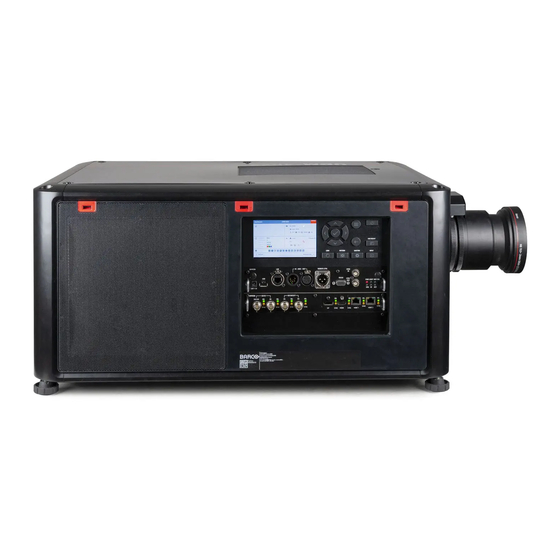
Page 19: Input & Communication
3. Input & Communication 3. INPUT & COMMUNICATION Introduction General The Input & Communication side of the projector consists of a local keypad, a communication panel, a venues & hospitality Input (V&H) and a free input slots. The free input slot can be used for optional modules (e.g. Virtual & Augmented Reality Input (V&AR)). Image 3-1 Local Keypad and touch panel Optional antenna for WiFi connection... - Page 20 3. Input & Communication Input specifications HDMI Up to 297 MHZ pixel clock YCbCr 4:4:4 For future release • YCbCr 4:2:2 and YCbCr 4:2:0 • 3D support • Interlaced support • HDCP 1.4 • HDCP 2.2 HDMI 1.4a Support for ’Deep Color’ up to 12 bit per color Audio not supported Video timings...
- Page 21 3. Input & Communication HDMI 4096 x 2160 @25 Hz 4096 x 2160 @30 Hz 4096 x 2160 @50 Hz 4096 x 2160 @60 Hz HDBase-T 25 – 297 MHz pixel clock Colors • YCbCr 4:2:2 • YCbCr 4:4:4 • Color 24 bpp •...
- Page 22 3. Input & Communication HDBase-T 3840 x 2160 @30 Hz 4096 x 2160 @24 Hz 4096 x 2160 @25 Hz 4096 x 2160 @30 Hz 3G SDI follows the SMPTE 425M standard Level A HD-SDI follows the SMPTE 292M standard Color space YCbCr RGB : future release...
- Page 23 3. Input & Communication DisplayPort For future release: • Passive 3D support • Interlaced support • HDCP 1.4 Audio not supported DP 1.2 Support for ’Deep Color’ up to 12 bit per color Bitrate Support • Reduced Bit Rate (RBR) •...
- Page 24 3. Input & Communication DisplayPort 3840 x 2400 @50 Hz 3840 x 2400 @60 Hz 4096 x 2160 @24 Hz 4096 x 2160 @30 Hz 4096 x 2160 @50 Hz 4096 x 2160 @60 Hz 3D Support 1280 x 720 @50 Hz 1280 x 720 @60 Hz 1920 x 1080 @50 Hz 4096 x 2160 @24 Hz...
-
Page 25: Communication Connections
3. Input & Communication DP 1.2 Support for ’Deep Color’ up to 12 bit per color Video timings 640 x 480 @60 Hz 720 x 480 @60 Hz 800 x 600 @60 Hz 1024 x 768 @60 Hz 1280 x 720 @50 Hz 1280 x 720 @60 Hz 1280 x 960 @60 Hz 1280 x 1024 @60 Hz... - Page 26 3. Input & Communication DMX interface DMX is used as communication bus between different devices in the light technic. Each device has an input and an output, so that the bus can be looped between the different devices. According the standard a five wire cable with XLR connector is used. You can use the DMX input port to connect a DMX device (DMX console) to the projector.
-
Page 27: Led And Button Indication Chart
3. Input & Communication RS422 An EIA serial digital interface standard that specifies the electrical characteristics of balanced (differential) voltage, digital interface circuits. This standard is usable over longer distances than RS-232. This signal governs the asyn- chronous transmission of computer data at speeds of up to 920,000 bits per second. It is also used as the serial port standard for Macintosh computers. - Page 28 3. Input & Communication Color status Description No error ERR (error LED) RED toggles on/off Error ORANGE toggles on/off Warning IR signal received GREEN IR signal acknowledged R5906112 UDX SERIES 24/05/2017...
-
Page 29: Getting Started
4. Getting Started 4. GETTING STARTED How controlling the projector ? The projector can be controlled by the local keypad, by the remote control unit or by browser application. Location of the local keypad ? The local keypad is located on the input side of the projector. Remote control functions. -
Page 30: Power On Projector
4. Getting Started Remote Control Unit buttons Backspace (while entering Button pressed indicator. values) XLR connector. Shutter Open. Decimal mark (while entering Shutter Close. values) Macro button. Touch Panel On/Off. Menu Back. OSD On/Off. Default button. Lens Zoom. Lens Focus. Lens Shift. - Page 31 4. Getting Started Image 4-1 Mains switch When ’0’ is pressed, the projector is switched off. When ’I’ is pressed, the projector is switched on. The projector starts up to standby mode. The Power on/off button will blink until standby mode is achieved. Once in standby mode, the Power on/off button will be lit WHITE, but the display will be off.
-
Page 32: Switching To Standby
4. Getting Started Starting image projection 1. Make sure the available sources are connected to the appropriate input ports. Tip: If properly connected, the “SYNC” LED will lit up ORANGE. 2. Press the Input Selection button on the keypad or on the remote control until: the LED of the selected source (the “SEL”... -
Page 33: Using The Rcu
4. Getting Started Image 4-5 2. Unplug the power cord from the projector. Using the RCU Pointing to the reflective screen 1. Point the front of the RCU to the reflective screen surface. Image 4-6 IR control via reflective screen Hardwired to the XLR input 1. -
Page 34: Projector Address
4. Getting Started 45° 45° 45° 45° 45° 45° Image 4-7 RCU to one of the IR sensors Projector Address Projector address Address installed in the projector to be individually controlled. Broadcast address Projector will always execute the command coming from a RCU programmed with that broadcast address. 4.6.1 Controlling the projector Why a projector address? -
Page 35: Displaying And Programming Addresses Into The Rcu
4. Getting Started 4.6.2 Displaying and Programming addresses into the RCU Displaying the Projector Address on the Screen. 1. Press the Address button to see the projector address (proximately 2 seconds). The projector’s address is displayed on the LCD status screen. How to Program an Address into the RCU? 1. - Page 36 4. Getting Started Quick test pattern selection 1. Press the Test pattern button on the remote control or local keypad. Image 4-10 A first test pattern will be displayed. 2. Press as may times on that button until the desired pattern is displayed R5906112 UDX SERIES 24/05/2017...
-
Page 37: Graphic User Interface (Gui)
5. Graphic User Interface (GUI) 5. GRAPHIC USER INTERFACE (GUI) Overview • Overview • Navigation • Test Patterns Overview GUI - Main Menu overview The projector on screen display (OSD) is the primary user interface (UI). From here, you can review and adjust all projector and display settings. -
Page 38: Test Patterns
5. Graphic User Interface (GUI) Use the arrow keys (Menu Navigation buttons) to navigate to the desired menu item (2). The background color changes to light blue. Press the Menu Selection button (center key of the arrow keys), also called OK button, to activate that item and to jump one level deeper (3). - Page 39 5. Graphic User Interface (GUI) Color bars Checker board Blue / Green / Red / White Convergence Focus Aspect Cross hatch Mono scope You can select one of the following Output test patterns: Vertical / diagonal lines Step bar Blemish zone Checkerboard Color bars Convergence...
- Page 40 5. Graphic User Interface (GUI) R5906112 UDX SERIES 24/05/2017...
-
Page 41: Gui - Source
6. GUI – Source 6. GUI – SOURCE About the Source menu This menu is used to select, review and configure sources into the projector. Overview of features • Source Selection • Connector Settings Source Selection How to select? 1. Press Menu to activate the menus and select Source. Image 6-1 Select Source 2. - Page 42 6. GUI – Source The Select Source menu is displayed with the actual available sources filled out. 3. Scroll down to the bottom of the list and select Connector Settings. Image 6-4 The available sources are displayed. Image 6-5 Select source 4.
-
Page 43: Gui - Image
7. GUI – Image 7. GUI – IMAGE Overview of features • Setting image levels manually • P7 Realcolor • Setting the output resolution Setting image levels manually Purpose Contrast: Change the contrast of the complete output signal (main and PiP window together) of the projected image. Brightness: Change the brightness of the complete output signal (main and PiP window together) of the projected image. -
Page 44: P7 Realcolor
7. GUI – Image 2. Use the ◄ or ► key to change the brightness until the desired value is reached (adjustable between –1 and 1). Image 7-4 Brightness slider 3. Use the ▲ or ▼ key to select Contrast or Saturation. go to Home - Image and select Contrast or Saturation. -
Page 45: Setting The Output Resolution
7. GUI – Image How to set the P7 desired values 1. In the main menu, select Image → Advanced → P7 Realcolor. Image 7-7 Advanced menu — P7 Realcolor The P7 menu is displayed. Image 7-8 P7 Realcolor menu 2. - Page 46 7. GUI – Image Image 7-9 Advanced menu — Output resolution The current active output resolution is indicated at the bottom of the selection button. 2. Select the desired output resolution. Possible resolutions: 4K UHD: 4K images, using the actuator. WQXGA: 2K images.
-
Page 47: Gui - Installation
8. GUI – Installation 8. GUI – INSTALLATION Overview of features • Configuring the lens, shift • Orientation • Warping • Blending • Laser illumination Configuring the lens, shift What can be done? The image can be shifted by using the vertical and horizontal lens shift. Vertical and Horizontal Shift 1. -
Page 48: Warping
8. GUI – Installation How to set the correct orientation 1. In the main menu, select Installation → Orientation. Image 8-3 Installation menu, Orientation The Orientation menu is displayed. Image 8-4 Orientation menu 2. Use the ▲ or ▼ key to select the desired mounting position and press OK button to activate. Use the ▲... -
Page 49: Warping - Screen Size
8. GUI – Installation Image 8-7 Image 8-6 8.3.3 Warping – Screen Size About (Warp) Screen Size adjustment If the used source aspect ratio is different than the projector aspect ratio, e.g. source is 16:9 and projector is 16:10, then black bars will be projected. -
Page 50: Warping - 4 Corners Adjustment
8. GUI – Installation Image 8-10 Screen size 2. Select either Screen width or Screen height. 3. Set the new value to shrink either the width or height of the warp outline so that the outline is equal with the active source. Tip: A red border will be projected along with the current image. -
Page 51: Warping - Bow
8. GUI – Installation The 4Corners menu is displayed. Image 8-13 4Corners Warping 2. To enable 4 corners, make sure the 4 corners slider is set to On. The slider is enabled when set to the right and when it is colored blue. 3. -
Page 52: Blending
8. GUI – Installation Image 8-15 Installation menu, Warp 2. In the Warp menu, select Bow. Image 8-16 Warp menu, Bow A check symbol at the bottom right corner indicates that the bow function is activated. 3. To enable Bow correction, make sure the Bow slider is set to On. The slider is enabled when set to the right and when it is colored blue. -
Page 53: Blend Zones
8. GUI – Installation 8.4.1 Blend Zones About offset and blending width or height Offset is used to clip the image. The larger the offset value, the more the image is masked (by black bar) at the corresponding side. E.g. Top offset of 100 will blank the top 100 lines. Height or width is used to create a blending zone with a smooth brightness drop off. - Page 54 8. GUI – Installation Image 8-20 Start position (offset) Blending width 5. First select an offset and click Menu selection to activate the selection. Use the arrow keys to change the value (the start position of the blending) Repeat for the other edges if necessary. 6.
-
Page 55: Laser Illumination
8. GUI – Installation Image 8-21 Set up for projector 1 Image 8-22 Set up for projector 2 Laser illumination What can be done? Within a certain power mode, the light output of the laser can be reduced by reducing the laser power. How to reduce the power 1. - Page 56 8. GUI – Installation Image 8-24 Laser power adjustment R5906112 UDX SERIES 24/05/2017...
-
Page 57: Gui - System Settings
9. GUI – System Settings 9. GUI – SYSTEM SETTINGS Overview of features • Communication, LAN setup • GSM configuration • IR control • Themes • Service Menu • Reset Communication, LAN setup About a network connection A network connection can be made via a wired connection or via the optional wireless unit. 9.1.1 Introduction to a Network connection DHCP... -
Page 58: Wired Ip Address Set Up
9. GUI – System Settings 9.1.2 Wired IP address set up How to automatically set up the IP address 1. In the main menu, select System Settings → Communication → LAN. Image 9-1 Communication menu, LAN The LAN menu is displayed Image 9-2 LAN menu 2. -
Page 59: Gsm Configuration
9. GUI – System Settings 2. Disable Automatic. Put the switch to the left. The switch becomes gray. 3. Use the ▲ or ▼ key to select Address and press OK button to activate the input box. 4. Use the ▲ or ▼ key to change the selected character. Use the ◄... -
Page 60: Ir Control
2. To change the broadcast address select the radio button of your choice. The following choices are possible: Generic IR (address 0) Barco broadcast IR (address 1) 3. Select APPLY and click OK to apply the changes. 9.3.2 Projector address... -
Page 61: Ir Sensors
9. GUI – System Settings Image 9-9 Communication menu, IR control The IR control menu is displayed. Image 9-10 IR control menu 2. Select the current projector address and enter a new address. 3. Select APPLY and click OK to apply the changes. From now on the projector will only listen to this new address and to its broadcast address. -
Page 62: Themes
9. GUI – System Settings 2. To disable an IR sensor, select the slider and drag to the left. A blue slider means an active IR sensor. A gray slider means an inactive IR sensor. 3. Select APPLY and click OK to apply the changes. Themes About Themes Themes are used to apply a predefined functionality to the OSD display. -
Page 63: Service - Color
9. GUI – System Settings 9.5.1 Service – Color AUTION The native colors have been measured and set during factory production. Do not change them, unless parts of the optical path have been replaced due to servicing. If you need to change the native colors on the device, make sure to also perform a P7 calibration, using the Projector Toolset and a chroma meter. -
Page 64: Lens Calibration
9. GUI – System Settings How to display the statistics 1. In the main menu, System Settings → Service. Image 9-18 2. Enter the service code. 3. In the Service menu, select Statistics. Image 9-19 The Statistics will be displayed. Image 9-20 9.5.3 Lens Calibration... -
Page 65: Lens Features
9. GUI – System Settings Image 9-22 System Settings menu — Lens Calibration The Lens Calibration menu is displayed. Image 9-23 Lens Calibration menu 4. In the Lens Calibration menu, select the desired calibration action and click OK. You can select one of the following functions: Horizontal shift Vertical shift The text Calibration in progress will be displayed next to selected function until the calibration is completed. -
Page 66: Reset
9. GUI – System Settings The Lens features menu is displayed. Image 9-26 Lens features Depending on the lens type, different functions are available such as: Focus Horizontal lens shift Vertical lens shift Shutter Zoom 4. To enable/disable a feature, click on the slider and drag it to the left to disable the feature or the right to enable the feature. When enabled, the slider becomes blue;... - Page 67 9. GUI – System Settings Image 9-27 System Settings menu, Reset The Reset menu is displayed. Image 9-28 Reset menu 2. Navigate to the checkbox next to the settings that need to be reset and press OK. Multiple selection are possible. 3.
- Page 68 9. GUI – System Settings R5906112 UDX SERIES 24/05/2017...
-
Page 69: Status Menu
10. Status menu 10. STATUS MENU This is a status menu only. No changes can be made to settings from this menu. Overview • Status menu overview 10.1 Status menu overview Status menu While in the main menu, press Status. Image 10-1 Status overview Source status... - Page 70 10. Status menu R5906112 UDX SERIES 24/05/2017...
-
Page 71: Maintenance
11. Maintenance 11. MAINTENANCE About this chapter This chapter contains general maintenance procedures. Overview • Cleaning the lens • Cleaning the exterior of the projector 11.1 Cleaning the lens To minimize the possibility of damage to optical coatings, or scratches to lens surfaces follow the cleaning procedure as described here precisely. - Page 72 11. Maintenance R5906112 UDX SERIES 24/05/2017...
-
Page 73: Specifications
Dimensions of a UDX • Dimensions of the rigging frame • Dimensions of the flight case • Technical Regulations A.1 Specifications of the UDX 4K32 Specifications Projector type 4K UHD 3-chip DLP digital projector Technology 0.9" DMD™ x3 Resolution 3,840 x 2,160 (4K UHD) / 2,560 x 1,600 (native) -
Page 74: Specifications Of The Udx 4K22
A. Specifications Network connection 10/100 base-T, RJ-45 connection, Wifi (optional) Power requirements 120-160V / 200-240V (+/- 10%), 20A, 50-60Hz Max. power consumption 2,900W nom/3,100W max / STBY less than 10W Noise level (typical at 25°C/77°F) 52dB(A) Operational ambient temperature 0-40°C / 32°-104°F Operational humidity 0-80% (non condens) Dissipation BTU... -
Page 75: Specifications Of The Udx W32
A. Specifications Software tools Projector Toolset + Android app + iOS app Control XLR wired + IR, RS232, Wifi, GSM (opt) Network connection 10/100 base-T, RJ-45 connection, Wifi (optional) Power requirements 120-160 V / 200-240 V (+/- 10%), 20 A, 50-60 Hz (reduced power on 110 V) Max. -
Page 76: Specifications Of The Udx W22
A. Specifications Input resolutions From NTSC up to 4K (4,096 x 2,160) Max. pixel clock 600 MHz Software tools Projector Toolset + Android app + iOS app Control XLR wired + IR, RS232, Wifi, GSM (opt) Network connection 10/100 base-T, RJ-45 connection, Wifi (optional) Power requirements 120-160V / 200-240V (+/- 10%), 20A, 50-60Hz Max. -
Page 77: Specifications Of The Udx U32
A. Specifications Inputs Dual HDBt; HDMI 2.0 (HDCP 2.2); DP 1.2 (HDCP 1.3); Quad SDI/HDSDI/dual HDSDI/6G/BarcoLink Optional Inputs Quad DP1.2 Input resolutions From NTSC up to 4K (4,096 x 2,560) Max. pixel clock 600 Mhz Software tools Projector Toolset + Android app + iOS app Control XLR wired + IR, RS232, Wifi, GSM (opt) Network connection... - Page 78 A. Specifications CLO (constant light output) Standard Active eye wear (optional), passive circular (optional); 3 flash up to 200Hz Inputs Dual HDBt; HDMI 2.0 (HDCP 2.2); DP 1.2 (HDCP 1.3); Quad SDI/HDSDI/dual HDSDI/6G/BarcoLink Optional Inputs Quad DP1.2 Input resolutions From NTSC up to 4K (4,096 x 2,160) Max.
-
Page 79: Dimensions Of A Udx
A. Specifications A.6 Dimensions of a UDX Overview Image A-1 Dimensions, in mm Geometrical centre A.7 Dimensions of the rigging frame Overview 1018,97 463,3 978,38 Image A-2 Dimensions, in mm R5906112 UDX SERIES 24/05/2017... -
Page 80: Dimensions Of The Flight Case
A. Specifications A.8 Dimensions of the flight case Overview 1133 Image A-3 Dimensions, in mm A.9 Technical Regulations Certificates RoHS Image A-5 Image A-6 Image A-7 Image A-4 Image A-8 Rohs Rohs OK CE mark EAC mark CCC mark Image A-9 Image A-11 Image A-10 FCC label... -
Page 81: Environmental Information
Registered office address: President Kennedypark 35, 8500 Kortrijk, Belgium Contact address: Beneluxpark 21, 8500 Kortrijk, Belgium Importers contact information To find your local importer, contact Barco directly or one of Barco’s regional offices via the contact information given on Barco’s web site, www.barco.com. R5906112 UDX SERIES 24/05/2017... -
Page 82: Download Product Manual
The month and year of production is indicated on the product ID label on the product itself. B.4 Download Product Manual Download Product Manual Product manuals and documentation are available online at www.barco.com/td. Registration may be required; follow the instructions given on the website. IMPORTANT! Read Installation Instructions before connecting equipment to the mains power supply.