Table of Contents
Advertisement
Quick Links
Advertisement
Table of Contents

Related Manuals for Barco UDM


Summary of Contents for Barco UDM
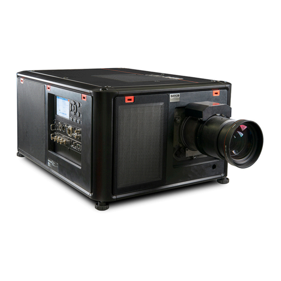
- Page 1 Installation manual ENABLING BRIGHT OUTCOMES...
- Page 2 Barco NV Beneluxpark 21, 8500 Kortrijk, Belgium www.barco.com/en/support www.barco.com Registered office: Barco NV President Kennedypark 35, 8500 Kortrijk, Belgium www.barco.com/en/support www.barco.com...
- Page 3 Barco. If the purchaser or a third party carries out modifications or repairs on goods delivered by Barco, or if the goods are handled incorrectly, in particular if the systems are operated incorrectly or if, after the transfer of risks, the goods are subject to influences not agreed upon in the contract, all guarantee claims of the purchaser will be rendered invalid.
-
Page 5: Table Of Contents
Table of contents 1 Safety information....................................7 General Considerations .................................8 Important safety instructions..............................10 Product safety labels..................................14 High Brightness precautions: Hazard Distance ......................15 HD for fully enclosed projection systems...........................17 HD in function of modifying optics ............................18 Radio equipment (optional) ...............................19 Compliance ......................................20 Download Product Manual ................................21 2 Installation process....................................23 Preparation process ..................................24... - Page 6 Installation of an input board..............................55 4.10 Removal of an input board.................................57 4.11 Software update....................................58 5 Lenses..........................................61 Lens installation ....................................62 Installing the lens safety cable..............................64 Lens removal.....................................68 UST lenses ......................................70 5.4.1 About UST lenses...............................70 5.4.2 Installation of the lens safety cable on the UST lens ................71 5.4.3 Installing the UST lens .............................71 5.4.4...
-
Page 7: Safety Information
Ensure that you understand and follow all safety guidelines, safety instructions and warnings mentioned in this chapter before installing the UDM projector. Clarification of the term “UDM” used in this document When referring in this document to the term UDM means that the content is applicable for following Barco poducts: •... -
Page 8: General Considerations
• Before operating this equipment please read this manual thoroughly and retain it for future reference. • Installation and preliminary adjustments must be performed by qualified Barco personnel or by authorized Barco service dealers. • All warnings on the projector and in the documentation manuals must be adhered to. - Page 9 The term USER and OPERATOR refers to any person other than SERVICE PERSONNEL, AUTHORIZED to operate professional projection systems. The UDM projector is intended "FOR PROFESSIONAL USE ONLY" by AUTHORIZED PERSONNEL familiar with potential hazards associated with high voltage, high intensity light beams and high temperatures generated by the light source and associated circuits.
-
Page 10: Important Safety Instructions
Safety information 1.2 Important safety instructions To prevent risk of electrical shock • This product should be operated from a mono phase AC power source. Ensure that the mains voltage and capacity matches the projector electrical ratings:120-180V/200-240V (+/-10%), 16/12A 60/50Hz. If you are unable to install the AC requirements, contact your electrician. - Page 11 • Max units in hanging configuration, 2 units. • When hanging projectors on a truss with the Barco stacking frame, always secure the stack with safety cables between the projectors and the truss. • When using the projector in a hanging configuration, always mount 2 safety cables. See installation manual for the correct use of these cables.
- Page 12 For lens cleaning follow the instructions precisely as stipulated in the projector manual. • Only use zoom lenses of the Barco TLD+ series on the 4K models of the projector. Using other lenses will damage the internal optics. For suitable fixed TLD+ lenses contact Barco or see Barco website.
- Page 13 Replacement parts: When replacement parts are required, be sure the service technician has used original Barco replacement parts or authorized replacement parts which have the same characteristics as the Barco original part. Unauthorized substitutions may result in degraded performance and reliability, fire, electric shock or other hazards.
-
Page 14: Product Safety Labels
Safety information 1.3 Product safety labels Light beam related safety labels Label image Label description Label location Hazard RG3: not for household use symbol Hazard RG3: optical radiation warning symbol Hazard class 2: laser radiation warning symbol. 0.95 mW - 638 nm. WARNING! DO NOT LOOK INTO THE BEAM NO DIRECT EYE EXPOSURE TO THE PROJECTOR BEAM IS PERMITTED LASER RADIATION - DO NOT STARE INTO LASER RANGING BEAM RG3 IEC EN 62471-5:2015... -
Page 15: High Brightness Precautions: Hazard Distance
Safety information 1.4 High Brightness precautions: Hazard Distance Hazard Distance (HD) is the distance measured from the projection lens at which the intensity or the energy per surface unit becomes lower than the applicable exposure limit on the cornea or on the skin. - Page 16 The LIP shall be installed by Barco or by a trained and Barco-authorized installer or shall only be transferred to laser light show variance holders. This is applicable for dealers and distributors since they may need to install the LIP (demo install) and/or they transfer (sell, rent, lease) the LIP.
-
Page 17: Hd For Fully Enclosed Projection Systems
Safety information 1.5 HD for fully enclosed projection systems Hazard Distance (HD) is the distance measured from the projection lens at which the intensity or the energy per surface unit becomes lower than the applicable exposure limit on the cornea or on the skin. -
Page 18: Hd In Function Of Modifying Optics
Safety information 1.6 HD in function of modifying optics Hazard distance Image 1–5 R5911438 /09... -
Page 19: Radio Equipment (Optional)
NO PL 5250 MHz frequency range. UKNI Hereby, Barco declares that the radio equipment type UDM is in compliance with Directive 2014/53/EU. The full text of the EU declaration of conformity is available at the following internet address: https://www. barco. -
Page 20: Compliance
Safety information 1.8 Compliance UK Compliance This product is fit for use in the UK. Authorised Representative: Barco UK Ltd Address: Building 329, Doncastle Road Bracknell RG12 8PE, Berkshire, United Kingdom R5911438 /09... -
Page 21: Download Product Manual
Safety information 1.9 Download Product Manual Download Product Manual Product manuals and documentation are available online at www.barco.com/td. Registration may be required; follow the instructions given on the website. IMPORTANT! Read Installation Instructions before connecting equipment to the mains power supply. - Page 22 Safety information R5911438 /09...
-
Page 23: Installation Process
This chapter gives an overview of all the different stages in the installation process that has to be followed in chronological order to set the UDM projector up and running. The stages are grouped in three processes: Preparation, Installation and Options. Each stage is briefly described and refers to more detailed step by step procedures in this manual or reference is made to other online product manuals. -
Page 24: Preparation Process
Installation process 2.1 Preparation process Prepare for installation Ensure that you understand all safety topics described in the chapter “Safety information”, page Check if all installation requirements are fulfilled such as: • the environmental conditions of the installation area, • the electrical facilities, •... -
Page 25: Installation Process
Use a solid pedestal to place a single UDM projector on (with or without rigging frame) ◦ Use a solid pedestal and UDM rigging frames for stacking the UDM projectors up to maximum 3 units high. In case of a hanging installation: ◦... - Page 26 Installation process Acclimatize and configure the used lens. Calibrate the lens and potential focus drift. • To calibrate the mounted lens, use Projector Toolset or the Lens calibration menu in the GUI. For detailed information, see the user guide of Projector toolset and the projector. •...
-
Page 27: Additional Install Options
Installation of the external cooler module For installation and adjusting instructions see installation manual of the external cooler module. Note: The external cooler only applies to the UDM-4K22 and W22, and can only be used after physically upgrading the device for the external cooler. - Page 28 Installation process R5911438 /09...
-
Page 29: Prepare To Install
In addition, careful consideration of things such as image size, projector placement and type of screen to use are critical to the optimum use of this projection system. Barco provides a guarantee relating to manufacturing as part of the legally stipulated terms of guarantee. Observing the specification mentioned an this chapter is critical for the projector performance. -
Page 30: Installation Requirements
Prepare to install 3.1 Installation requirements Environment conditions Table below summarizes the physical environment in which the projector safely operates or can be stored. Operating Non-Operating Environment Ambient Temperature 0-1000 meter: 0°C (32°F) to 40°C (104°F) -15°C (5°F) to 60°C (140°F) (depends on altitude) 1000-3000 meter: 0°C (32°F) to 30°C (86°F) Humidity... - Page 31 Prepare to install Image 3–2 Airflow, hot air Since the projector is foreseen to be stacked while in the rigging frame, the minimum distance space around the top and bottom air inlets should be the distance between two stacked projectors while in the rigging frame.
-
Page 32: Unpacking The Projector
Prepare to install 3.2 Unpacking the projector Unpacking process and handling The projector can be delivered in a cardboard box on a pallet or within a rigging frame inside a flight case. This chapter describes how to unpack the projector from the cardboard box. For how to handle the projector with rigging frame and flight case see “Flight case and rigging frame”, page The box and pallet is secured with a banding and locking clips. - Page 33 Prepare to install Image 3–4 Save the original shipping cardboard box and packing material. They will be necessary if you ever have to ship your projector. For maximum protection, repack your projector as it was originally packed at the factory. A plastic lens holder cover is placed into the lens opening of the projector.
-
Page 34: Initial Inspection
This check should confirm that there are no broken knobs or connectors, that the cabinet and panel surfaces are free of dents and scratches, and that the operating panel is not scratched or cracked. The Barco Sales and Service office should be notified as soon as possible if this is not the case. -
Page 35: Projector Orientations
Prepare to install 3.4 Projector orientations Supported projector orientations The projector can be installed on a table or upside down on the ceiling and this in a front projection or rear projection configuration. Depending on the physical configuration of the projector the projected image has to be rotated and/or mirrored as well. - Page 36 Prepare to install Some lenses (e.g. UST lenses) may require that the projector orientation needs to be adapted for the desired outcome. R5911438 /09...
-
Page 37: Projector Positioning
Prepare to install 3.5 Projector positioning Positioning the projector The projector should be installed at right angles (horizontally and vertically) to the screen at a distance PD. Note the distance (A) between lens centre and table surface is slightly variable. This distance (A) is nominal 223 mm in case all feet are turned in completely and the vertical lens shift is set to zero (0). -
Page 38: Projector Shift And Tilt Range
Prepare to install 3.6 Projector shift and tilt range Shift range The lens can be shifted with respect to the DMD (P) which result in a shifted image on the screen (Off-Axis). A 100% shift means that the centre point of the projected image is shifted by half the screen size. In other words, the centre point of the projected image falls together with the outline of the image in an On-Axis projection. - Page 39 Prepare to install 360° 360° Image 3–9 R5911438 /09...
-
Page 40: Lens Selection
How to select the right lens Determine the required screen width (SW). Determine the approximate position of the projector in the room. Start up the Lens Calculator on the Barco website: https://lenscalculator.barco.com/ to determine the possible lenses for your configuration. -
Page 41: Available Lenses
Limited amount of available lenses The 4k variants of the UDM projectors have an Actuator built in them to help provide a clear 4K image. This extra device means that less space is available in the projector for lenses, thus causing a more restricted amount of lenses that can be used. - Page 42 This table only takes into account active lenses at the moment of release of this manual. Lenses that have become end-of life or end-of service are not taken into account. Consult the Barco website for the most up-to-date information on active lenses.
-
Page 43: Download Projector Toolset
3.9 Download Projector Toolset About Projector Toolset Projector Toolset is a software tool to set up, configure, manage and control Barco projectors. The Projector Toolset software works with configurations that can be loaded. Several configurations can be controlled simultaneously. Even when the configurations are connected via different ways. - Page 44 Prepare to install R5911438 /09...
-
Page 45: Installation Procedures
Installation procedures Pulse RCU, battery installation ......................46 Connecting the projector with the power net..................48 Displaying and Programming addresses into the RCU..............49 Using the XLR connector of the RCU .....................50 Setting the projector addresses .....................51 Alignment of a table mounted projector...................52 Alignment of projector in the rigging frame ..................53 Wall or ceiling mount without rigging frame ..................54 Installation of an input board......................55... -
Page 46: Pulse Rcu, Battery Installation
Installation procedures 4.1 Pulse RCU, battery installation About the batteries for the remote control No batteries are included in the packaging. User has to buy batteries himself. Use 2 AA size (alkaline) batteries in the remote control. Before using your remote control, install the batteries first. How to install Push the battery cover tab with the fingernail a little backwards (1) and pull, at the same time, the cover upwards (2). - Page 47 Installation procedures CAUTION: Replace with the correct battery type. Use two AA size batteries. There is a risk of explosion if the battery is replaced with an incorrect type. CAUTION: Replace the battery as explained above. There is a risk of explosion if the battery is incorrectly installed.
-
Page 48: Connecting The Projector With The Power Net
Installation procedures 4.2 Connecting the projector with the power net CAUTION: Use only the power cord provided with the projector. WARNING: Do not attempt operation if the AC supply and cord are not within the specified voltage and power range. CAUTION: If the input voltage exceeds a defined limit, the “Overvoltage”... -
Page 49: Displaying And Programming Addresses Into The Rcu
Installation procedures 4.3 Displaying and Programming addresses into the RCU Displaying the Projector Address on the Screen. If the projector is on, press the menu key and navigate to the Status page. The projector address and the broadcast address can be seen under the Communication heading. The projector's address is displayed on the LCD status screen and / or the OSD. -
Page 50: Using The Xlr Connector Of The Rcu
Installation procedures 4.4 Using the XLR connector of the RCU Connecting a cable with the XLR connector will reset the broadcast address of the RCU to its default value '0'. How to use the XLR connector Remove the XLR cover by pulling it backwards. Image 4–5 Connect a cable with XLR plug into the XLR connector of the RCU. -
Page 51: Setting The Projector Addresses
Installation procedures 4.5 Setting the projector addresses Projector address Address installed in the projector to be individually controlled via the RCU or via the serial communication. Broadcast address Projector will always execute the command coming from a RCU programmed with that broadcast address. -
Page 52: Alignment Of A Table Mounted Projector
Installation procedures 4.6 Alignment of a table mounted projector How to align Place the projector in the desired location. Take into account the zoom range of the used lens and the size of the screen. Project one of the internal hatch patterns on the screen. Turn the adjustable feet in or out until the projected hatch pattern has a perfect rectangle shape and is leveled. -
Page 53: Alignment Of Projector In The Rigging Frame
Installation procedures 4.7 Alignment of projector in the rigging frame Skew the projector horizontally Turn the skew knob at the rear to adjust the rotation. Image 4–8 Tilt the projector Turn the tilt adjustment knob at the rear to tilt the projector Image 4–9 Rotating the projector Turn the rotate adjustment knob on the right side to rotate the projector. -
Page 54: Wall Or Ceiling Mount Without Rigging Frame
Installation procedures 4.8 Wall or ceiling mount without rigging frame General In case of installing the projector to other positions than desktop or ceiling, it is preferred to use the rigging frame designed for this purpose. In cases where this is not possible, suitable 3rd part brackets for safe installation must be used to secure the unit from damage or causing injury. -
Page 55: Installation Of An Input Board
Installation procedures 4.9 Installation of an input board WARNING: The procedures below may only be performed by Barco trained and qualified technicians. CAUTION: Always wear a wrist band which is connected to the ground while handling the electrostatic discharge (ESD) sensitive parts. - Page 56 Installation procedures IMPORTANT LAST STEP — Update the firmware of the installed module. Use the complete software package to install the firmware via Projector Toolset or USB stick. Tip: When a complete new software image is placed on the projector, all programmable components will be updated with the latest version.
-
Page 57: Removal Of An Input Board
Installation procedures 4.10 Removal of an input board WARNING: The procedures below may only be performed by Barco trained and qualified technicians. CAUTION: Always wear a wrist band which is connected to the ground while handling the electrostatic discharge (ESD) sensitive parts. -
Page 58: Software Update
Download the latest firmware (format .fw) from Barco's website in the same way as for Projector Toolset. Start Projector Toolset and make a connection with the projector. For more information, see the “Projector Toolset”... - Page 59 Always contact Barco if you want to make sure a downgrade will not hurt your device.
- Page 60 Installation procedures R5911438 /09...
-
Page 61: Lenses
Lenses R5911438 /09... -
Page 62: Lens Installation
Lenses 5.1 Lens installation WARNING: Only use TLD+ ZOOM lenses. Using other lenses can touch and damage the mechanics of the build-in Actuator! This can result in loud rattling noises and a damaged Actuator. How to install Place the lens holder in the “unlocked” position. Do this by pulling the lens lock handle (reference 1, Image 5–1) outward and then towards the lens power supply socket (reference 2) as illustrated. - Page 63 Lenses Image 5–3 Lens installation Insert the lens until the connector seats into the socket and de secondary lock (reference 3) makes an audible clicking sound. Warning: Do not release the lens yet, as the lens may fall out of the lens holder. Secure the lens in the lens holder by sliding the primary lens lock handle into the “locked”...
-
Page 64: Installing The Lens Safety Cable
Lenses 5.2 Installing the lens safety cable When to use the lens safety cable The lens safety cable must be used in any circumstance where the projector is mounted above people. Do this to secure the mounted lens in the lens holder. Content of the lens safety cable kit (R9801196) •... - Page 65 Lenses Image 5–6 Image 5–7 Snap the first loop end of the safety cable into one of the following clips and let the loop end point downwards. 1. Configuration A: Use the upper clip on the side of the cable bundle (reference 2, Image 5–6).
- Page 66 Lenses Image 5–9 Example of Configuration A Image 5–10 Example of Configuration B Close the U-bolt and tighten it. Note: Make sure the safety cable is tightened around the lens before tightening the U-bolt nuts. Place the shackle through the free loop end of the safety cable. Connect the shackle on the truss or rigging frame.
- Page 67 Lenses Image 5–13 Carefully slide the safety cable through the cable clips. Make sure the cable is placed between the motor block and the cover plate. Slide the cable through the loop end at the beginning of the cable. Mount a U-bolt on the cable, with the open ends oriented outwards (reference 3, Image 5–13).
-
Page 68: Lens Removal
Lenses 5.3 Lens removal How to remove Support the lens with one hand while you unlock the lens holder by sliding the primary lock handle outwards and then towards the “unlocked” position as illustrated (Image 5–15). Image 5–15 Unlock the lens Pull down the secondary lock on the lower left side of the lens holder as illustrated (Image 5–16). - Page 69 Lenses It's recommended to place the dust cover of the original projector packaging back into the lens opening to prevent intrusion of dust. Image 5–17 R5911438 /09...
-
Page 70: Ust Lenses
Image 5–19 Example of the 0.65 - 0.85:1 UST lens in both orientations For UDX, UDM and XDM projectors, the motor block must always be located above the lens body (ref. 1) when facing the projector from the front side in table mount. For HDX/HDF series the motor block must always be located at the right side (ref. -
Page 71: Installation Of The Lens Safety Cable On The Ust Lens
The Short Throw 90° zoom lens is delivered with the motor block mounted in the orientation for left projection of the current generation projectors (UDX, UDM, XDM) in table mount. To change the motor block orientation see procedure “Change the motor block orientation”, page... -
Page 72: Adjustment Of The Ust Lens
Lenses 1.5 mm Image 5–22 Gently insert the lens. Ensure the lens connector matches the electrical socket on the lens holder. Insert the lens until the connector seats into the socket. Note: The secondary lens lock (ref. 2) makes an audible clicking sound when latching. Caution: Do not release the lens yet, keep pushing the lens against the front plate! Image 5–23 Example of mounting the UST lens... - Page 73 Lenses How to adjust the UST lens Start up the projector and projector the focus pattern on the screen. See user manual of the projector for detailed instructions. Rotate the "adjusting ring for various throw distance" (Ring-A) to the position of the throw distance you need.
-
Page 74: Change The Motor Block Orientation
Lenses 5.4.5 Change the motor block orientation The illustrations in this procedure are a single example, shifting the motor block rotation from UDX left side projection to HDX/HDF left side projection (seen from the rear side of the projector in table mount). - Page 75 Lenses 1.5 mm Image 5–30 • If no, turn the set screw out of the mounting plate until it doesn't exceed on the other side of the mounting plate. 0 mm Image 5–31 R5911438 /09...
- Page 76 Lenses R5911438 /09...
-
Page 77: Flight Case And Rigging Frame
Flight case and rigging frame Flight case ...........................78 Rigging frame..........................79 About flight case and rigging frame The projector can also be delivered with rigging frame installed inside a flight case. R5911438 /09... -
Page 78: Flight Case
Flight case The UDM flight case is designed to transport the UDM in a safe and secure manner, with or without being mounted in its rigging frame. There's also sufficient space in the flight case to place the projector while mounted in the UDM rigging frame. -
Page 79: Rigging Frame
54 Rigging frame The UDM series multifunctional rigging frame is designed for the Barco UDM projectors, and can not be used for other equipment. See rigging frame specific documentation for how to install the projector in to the frame. - Page 80 Flight case and rigging frame R5911438 /09...
-
Page 81: Pulse Sfp Input Use Cases
Pulse SFP input use cases Use case 1: SFP+ transceiver + Fiber connection (integrated or separated) ........82 Use case 2: Neutrik OpticalCon Duo + SFP+ transceiver + internal fiber ...........83 Use case 3: Neutrik OpticalCon Quad + SFP+ transceiver + internal fiber .........84 Use case 4: Loop-through mode ....................85 About this chapter This chapter describes the several use cases of the SFP input. -
Page 82: Use Case 1: Sfp+ Transceiver + Fiber Connection (Integrated Or Separated)
Optional breakout Optical adapter Dustproof Gasket Barco delivers only the SFP input and SFP+ fiber transceivers. The customer has to buy the SFP+ transceiver and the optional breakout adapter or the fiber integrated cable. How to configure the SFP input Remove the plate covering the access to the SFP cages. -
Page 83: Use Case 2: Neutrik Opticalcon Duo + Sfp+ Transceiver + Internal Fiber
Neutrik OpticalCon DUO Cable Internal fiber cable Barco delivers only the SFP input and SFP+ fiber transceivers. The customer has to buy the SFP+ transceiver and the optional breakout adapter or the fiber integrated cable. How to configure the SFP input Remove both plates covering the access to the Neutrik connector locations. -
Page 84: Use Case 3: Neutrik Opticalcon Quad + Sfp+ Transceiver + Internal Fiber
Advanced quad cable Internal fiber cable Barco delivers only the SFP input and SFP+ fiber transceivers. The customer has to buy the SFP+ transceiver and the optional breakout adapter or the fiber integrated cable. How to configure the SFP input Remove one plate covering the access to a Neutrik connector location. -
Page 85: Use Case 4: Loop-Through Mode
Neutrik OpticalCon Quad Advanced Quad cable Barco delivers only the SFP input and SFP+ fiber transceivers. The customer has to buy the SFP+ transceiver and the optional breakout adapter or the fiber integrated cable. How to configure the SFP input Remove both plates covering the access to a Neutrik connector locations. - Page 86 Pulse SFP input use cases R5911438 /09...
-
Page 87: Projector Covers
WARNING: Switch off the projector and disconnect the power cord from the projector and wait a few minutes (to discharge the capacitors) prior to start with this procedure, unless otherwise specified in the procedure. WARNING: All procedures in this chapter must be performed by “Barco authorized qualified service personnel”. R5911438 /09... -
Page 88: Cover Locks
Projector covers 8.1 Cover locks About All the covers are fastened with the same “easylock” tabs. Required tools Flat screwdriver 5 mm Unlocking Push down the inner side of the easylock with a screwdriver. Image 8–1 As a result the lock jumps loose. Locking Ensure that the cover is in the correct position. -
Page 89: Removal Of The Front, Side And Rear Covers
Projector covers 8.2 Removal of the front, side and rear covers About The method of removing the covers are equal for the front, side and rear covers. Remove the lens before removing the front cover. Required tools Flat screwdriver 5 mm How to remove the covers Remove the lens. -
Page 90: Removal Of Top Cover
Projector covers 8.3 Removal of top cover Required tools Torx screwdriver T20 How to remove the top cover. Release the 6 Torx screws indicated in the illustration. Image 8–7 Lift up the cover of the projector. R5911438 /09... -
Page 91: Installing The Projector Covers
Projector covers 8.4 Installing the projector covers CAUTION: Ensure that the top cover is reinstalled in the correct way. It is possible to turn the top cover 180 degrees horizontally, and it will still fit the attachment points. But then the air intake for the light processor fan will be out of position, and by that the cooling will not be sufficient. - Page 92 Projector covers R5911438 /09...
-
Page 93: A Dimensional Drawings
Dimensional drawings Dimensions of the projector ......................94 Dimensions of the rigging frame.....................95 Dimensions of the flight case ......................96 R5911438 /09... -
Page 94: Dimensions Of The Projector
Dimensional drawings A.1 Dimensions of the projector Dimensional drawing 175,5 Image A–1 Dimensions are given in millimeters. R5911438 /09... -
Page 95: Dimensions Of The Rigging Frame
Dimensional drawings A.2 Dimensions of the rigging frame Dimensional drawing CC Rigging points (Overall dimension) Image A–2 Dimensions are given in millimeters. R5911438 /09... -
Page 96: Dimensions Of The Flight Case
Dimensional drawings A.3 Dimensions of the flight case Dimensional drawing 1043 Image A–3 Dimensions are given in millimeters. R5911438 /09... -
Page 97: Glossary
Glossary Broadcast address Projector will always execute the command coming from a RCU programmed with that broadcast address. Hazard Distance (HD) is the distance measured from the projection lens at which the intensity or the energy per surface unit becomes lower than the applicable exposure limit on the cornea or on the skin. The light beam is considered (to be) unsafe for exposure if the distance from a person to the light source is less than the HD. - Page 98 Glossary R5911438 /09...
-
Page 99: List Of Tools
List of tools Allen wrench 2.5 mm. Cutter knife Flat screwdriver 5 mm Phillips screwdriver PH1 Torx screwdriver T10 Torx screwdriver T20 R5911438 /09... - Page 100 List of tools R5911438 /09...
-
Page 101: Index
Index Environment conditions 30 Address Program RCU 49 Flight case 77 Adjust Weight 78 UST lens 72 Front cover 89 Alignment Rigging frame 53 Table mounted projector 52 General Considerations 8 CE Certification 19 Compliance 20 Connection Hazard Distance 15, 17 Power cable 48 Modifying optics 18 Power net 48... - Page 102 Index Lens 62 Orientations 35 Installation process Positioning 37 Physical installation 25 Shift 38 Preparations 24 Shift range 38 Installation requirements Tilt 38 Clean air 31 Weight 31 Environment conditions 30 Projector Toolset 43 Pulse RCU battery 46 Laser radiation 9 Lens Available 41 Installation 62...
- Page 103 Index Unpacking 32 Use cases SFP input 81–85 User definition 9 UST lens 70 Introduction 70 UST Lens Safety cable 71 Vertical tilt range 38 Warnings Cooling liquid circuit 11 Weight Flight case 78 Projector 31 Rigging frame 79 RCU 50 R5911438 /09...
- Page 104 Index R5911438 /09...
- Page 106 R5911438 /09 | 2023-02-28 www.barco.com...