
Related Manuals for NETGEAR GS316EP


Summary of Contents for NETGEAR GS316EP
- Page 1 User Manual Gigabit Ethernet Plus Switches Models • GS316EP • GS316EPP NETGEAR, Inc. June 2021 350 E. Plumeria Drive 202-12181-01 San Jose, CA 95134, USA...
- Page 2 See the regulatory compliance document before connecting the power supply. For NETGEAR’s Privacy Policy, visit https://www.netgear.com/about/privacy-policy. By using this device, you are agreeing to NETGEAR’s Terms and Conditions at https://www.netgear.com/about/terms-and-conditions. If you do not agree, return the device to your place of purchase within your return period.
-
Page 3: Table Of Contents
Discover the switch's IP address to access its device UI....16 Discover the IP address and access the switch......16 Use the NETGEAR Switch Discovery Tool to discover the switch's IP address and access the device UI......16 Assign a fixed IP address to the switch........18 Set a fixed IP address for the switch through a network connection..................18... - Page 4 Deactivate a port-based or 802.1Q VLAN mode and delete all VLANs....................57 Chapter 5 Manage the Switch in Your Network Manage NETGEAR Switch Discovery Protocol.......60 Set up static link aggregation............60 Set up a link aggregation group..........61 Make a link aggregation connection...........62 Enable a link aggregation group..........62...
- Page 5 Gigabit Ethernet Plus Switches Manage the configuration file............72 Back up the switch configuration..........72 Restore the switch configuration..........73 Return the switch to its factory default settings......74 Use the RESET button to reset the switch........74 Use the device UI to reset the switch...........75 Control access to the device UI............75 HTTP and HTTPS management access..........76 Configure HTTP access settings...........77...
- Page 6 Gigabit Ethernet Plus Switches Appendix A Factory Default Settings and Technical Specifications Factory default settings..............106 Technical specifications..............107 Model GS316EP technical specifications.........107 Model GS316EPP technical specifications.......107 Appendix B Additional Switch Discovery and Access Information Access the switch from any computer...........110...
-
Page 7: Chapter 1 Hardware
• Firmware updates with new features and bug fixes are made available from time to time at netgear.com/support/download/. You can manually check for, and download, new firmware. If the features or behavior of your product do not match what is... -
Page 8: Related Documentation
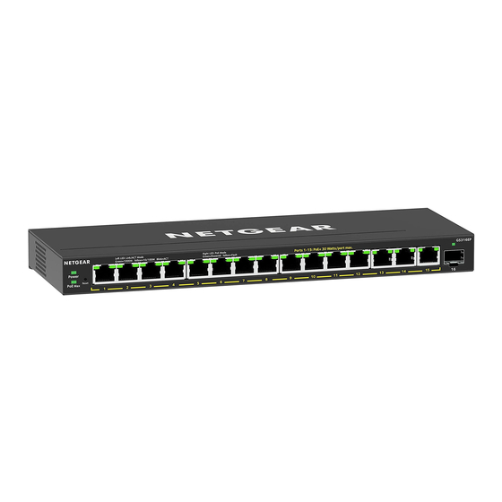
NETGEAR. On model GS316EP, ports 1 through 15 are PoE+ ports, and port 16 is an SFP port. On model GS316EPP, ports 1 through 15 are PoE+ ports, and port 16 is an SFP port. -
Page 9: 1000Base-X Sfp Slots
To enable fiber, copper, or long-distance connections on the switch, SFP slots accommodate standard 1G SFP transceiver modules, which are sold separately. For information about specific NETGEAR SFP transceiver modules and cables that are supported for the switch, visit netgear.com/business/wired/switches/ and click the ACCESSORIES tab, or see the datasheet for your specific switch. -
Page 10: Switch Label
Gigabit Ethernet Plus Switches Table 3. Supported SFP transceiver modules Speed and Medium Model Description 1G Ethernet short-reach fiber AGM731F SFP transceiver 1000BASE-SX 1G Ethernet long-reach fiber AGM732F SFP transceiver 1000BASE-LX 1G Ethernet copper AGM734 SFP transceiver 1000BASE-T Switch label The switch label on the bottom panel of the switch shows the serial number, MAC address, and default login information of the switch. - Page 11 Before connecting the product to outdoor cables or devices, see https://kb.netgear.com/000057103 for additional safety and warranty information. Failure to follow these guidelines can result in damage to your NETGEAR product, which might not be covered by NETGEAR’s warranty, to the extent permissible by applicable law.
- Page 12 • Depending on your product, use only a supplied power adapter or approved power cable: If your product uses a power adapter: If you were not provided with a power adapter, contact your local NETGEAR reseller. The power adapter must be rated for the product and for the voltage and current marked on the product electrical ratings label.
- Page 13 Gigabit Ethernet Plus Switches • If applicable to your product, the peripheral power cables are equipped with three-prong plugs to help ensure proper grounding. Do not use adapter plugs or remove the grounding prong from a cable. If you must use an extension cable, use a three-wire cable with properly grounded plugs.
-
Page 14: Chapter 2 Install And Access The Switch In Your Network
Install and Access the Switch in Your Network This chapter describes how you can install the switch in your network, get an IP address for the switch, and use the IP address to access the switch's device UI so you can set up, manage and monitor the switch. -
Page 15: Set Up The Switch In Your Network And Power On The Switch
Gigabit Ethernet Plus Switches Set up the switch in your network and power on the switch Figure 1. Example connections To set up the switch in your network and power on the switch: 1. Connect any port on the switch to a LAN port on a router that is connected to the Internet. -
Page 16: Discover The Switch's Ip Address To Access Its Device Ui
Use a computer and a web browser to discover the switch in your network and access the device UI of the switch: • Use the NETGEAR Switch Discovery Tool to discover the switch's IP address and access the device UI on page 16. - Page 17 Layer 2 network. 7. Open the NSDT. If the NETGEAR Switch Discovery Tool icon is in the dock of your Mac or on the desktop of your Windows-based computer, click or double-click the icon to open the program.
-
Page 18: Assign A Fixed Ip Address To The Switch
Gigabit Ethernet Plus Switches Assign a fixed IP address to the switch By default, the switch is configured to automatically receive an IP address from a DHCP server (or a router that functions as a DHCP server) in your network. However, certain events can cause the DHCP server to issue a new IP address to the switch, so if you need the switch to persistently have the same IP address, you can assign a fixed (static) IP address to the switch. -
Page 19: Assign A Fixed Ip Address By Connecting Directly To The Switch Off-Network
Gigabit Ethernet Plus Switches The button bar displays gray, indicating that the DHCP client of the switch is disabled, and the IP address fields become editable. 6. Enter the fixed (static) IP address that you want to assign to the switch and the associated subnet mask and gateway IP address. - Page 20 Gigabit Ethernet Plus Switches The password is the one that you specified the first time that you logged in. The password is case-sensitive. The HOME page displays. The right pane (or, depending on the size of your browser window, the middle pane) shows the IP address that is assigned to the switch.
-
Page 21: Change The Language Of The Device Ui
Gigabit Ethernet Plus Switches Change the language of the device UI By default, the language of the device UI is set to Auto so that the switch can automatically detect the language. However, you can set the language to a specific one. To change the language of the device UI: 1. -
Page 22: Register The Switch
Registering the switch allows you to receive email alerts and streamlines the technical support process. You can log in to your NETGEAR account at my.netgear.com to register your switch, or you can also register the switch through the device UI, in which case the switch must be connected to the Internet. -
Page 23: Chapter 3 Optimize The Switch Performance
Optimize the Switch Performance This chapter describes how you can optimize the performance of the switch and contains the following sections: • Set the quality of service mode and port rate limits • Manage individual port settings... -
Page 24: Set The Quality Of Service Mode And Port Rate Limits
Gigabit Ethernet Plus Switches Set the quality of service mode and port rate limits You can manually set the Quality of Service (QoS) modes to manage traffic: • Port-based QoS mode: Lets you set the priority (low, medium, high, or critical) for individual port numbers and lets you set rate limits for incoming and outgoing traffic for individual ports. - Page 25 Gigabit Ethernet Plus Switches Note: If you set a port rate limit, the actual rate might fluctuate, depending on the type of traffic that the port is processing. To use the port-based QoS mode and set the priority and rate limits for ports: 1.
-
Page 26: Use 802.1P/Dscp Quality Of Service
Gigabit Ethernet Plus Switches The EDIT PRIORITY page displays. c. For each port for which you want to set the priority, select Low, Medium, High, or Critical from the individual menu for the port. The default selection is High. d. Click the APPLY button. Your settings are saved and the EDIT PRIORITY page closes. -
Page 27: Manage Broadcast Filtering And Set Port Storm Control Rate Limits
Gigabit Ethernet Plus Switches 4. From the menu at the top of the page, select SWITCHING > QOS . The Quality of Service (QoS) page displays. 5. If the selection from the QoS Mode menu is Port-Based, do the following to change the selection to 802.1P/DSCP: a. - Page 28 Gigabit Ethernet Plus Switches To manage broadcast filtering and set the storm control rate limits for ports: 1. Open a web browser from a computer that is connected to the same network as the switch, or connected directly to the switch through an Ethernet cable. 2.
-
Page 29: Manage Individual Port Settings
Gigabit Ethernet Plus Switches Manage individual port settings For each individual port, you can set the port priority, set rate limits for incoming and outgoing traffic, set the port speed (by default, the speed is set automatically), enable flow control, and change the port name label. Set rate limits for a port You can limit the rate of incoming (ingress) traffic, outgoing (egress) traffic, or both on a port to prevent the port (and the device that is attached to it) from taking up too much... -
Page 30: Set The Priority For A Port
Gigabit Ethernet Plus Switches 6. From the In Rate Limit menu, Out Rate Limit menu, or both, select the rate in Kbps or Mbps. The default selection is No Limit. 7. Click the APPLY button. Your settings are saved. Set the priority for a port If the QoS mode on the switch is Port-Based (the default setting), you can set the priority for a port. -
Page 31: Manage Flow Control For A Port
Gigabit Ethernet Plus Switches 6. From the Priority menu, select Low, Medium, High, or Critical. The default selection is High. 7. Click the APPLY button. Your settings are saved. Manage flow control for a port IEEE 802.3x flow control works by pausing a port if the port becomes oversubscribed (that is, the port receives more traffic than it can process) and dropping all traffic for small bursts of time during the congestion condition. -
Page 32: Change The Speed For A Port Or Disable A Port
Gigabit Ethernet Plus Switches Your settings are saved. Change the speed for a port or disable a port By default, the port speed on all ports is set automatically (that is, the setting is Auto) after the switch determines the speed using autonegotiation with the linked device. We recommend that you leave the Auto setting for the ports. -
Page 33: Add Or Change The Name Label For A Port
Gigabit Ethernet Plus Switches • 100M full: The port is forced to function at 100 Mbps with full-duplex. Note: You cannot select Gigabit Ethernet as the port speed. However, if the setting from the Speed menu is Auto, the switch can use autonegotiation to automatically set the port speed to Gigabit Ethernet if the linked device supports that speed. - Page 34 Gigabit Ethernet Plus Switches Your settings are saved. Optimize the Switch User Manual Performance...
-
Page 35: Chapter 4 Use Vlans For Traffic Segmentation
Use VLANS for Traffic Segmentation This chapter describes how you can use VLANs to segment traffic on the switchj, and contains these sections: • VLAN overview • Activate the Basic Port-Based VLAN mode and assign VLANs • Manage advanced port-based VLANs •... -
Page 36: Vlan Overview
Gigabit Ethernet Plus Switches VLAN overview Virtual LANs (VLANs) consist of networked devices that are grouped logically into separate networks. You can group ports on a switch to create a virtual network consisting of the devices connected to the ports. You can group ports in VLANs using either port-based or 802.1Q criteria: •... -
Page 37: Activate The Basic Port-Based Vlan Mode And Assign Vlans
PVIDs, and manage a voice VLAN. The following table provides an overview of VLAN features that are supported on the switch. Table 4. Supported VLAN modes for the GS316EP and GS316EPP VLAN Feature Basic Advanced... -
Page 38: Manage Advanced Port-Based Vlans
Gigabit Ethernet Plus Switches The password is the one that you specified the first time that you logged in. The password is case-sensitive. The HOME page displays. 4. From the menu at the top of the page, select SWITCHING. The Quality of Service (QOS) page displays. 5. -
Page 39: Create An Advanced Port-Based Vlan
Gigabit Ethernet Plus Switches When you activate the Advanced Port-Based VLAN mode, VLAN 1 is added to the switch and all ports are made members of VLAN 1. This is the default VLAN in the Advanced Port-Based VLAN mode. To activate the Advanced Port-Based VLAN mode: 1. -
Page 40: Change An Advanced Port-Based Vlan
Gigabit Ethernet Plus Switches A login window opens. 3. Enter the device management password. The password is the one that you specified the first time that you logged in. The password is case-sensitive. The HOME page displays. 4. From the menu at the top of the page, select SWITCHING. The QOS page displays. - Page 41 Gigabit Ethernet Plus Switches To change an advanced port-based VLAN: 1. Open a web browser from a computer that is connected to the same network as the switch, or connected directly to the switch through an Ethernet cable. 2. Enter the IP address that is assigned to the switch. A login window opens.
-
Page 42: Delete An Advanced Port-Based Vlan
Gigabit Ethernet Plus Switches Delete an advanced port-based VLAN You can delete an advanced port-based VLAN that you no longer need. You cannot delete the default VLAN. Note: If you deactivate the basic or advanced port-based VLAN mode, all port-based VLANs are deleted. -
Page 43: Activate The Basic 802.1Q Vlan Mode
Gigabit Ethernet Plus Switches For more information about basic 802.1Q VLANs, see the following sections: • Activate the Basic 802.1Q VLAN mode • Create a basic 802.1Q VLAN and assign ports as members • Assign the port mode in a basic 802.1Q VLAN configuration •... -
Page 44: Create A Basic 802.1Q Vlan And Assign Ports As Members
Gigabit Ethernet Plus Switches 8. If you already determined which ports must function in trunk mode, for those ports, select Trunk (uplink) from the Mode menu. 9. Click the SAVE button. Your settings are saved. Create a basic 802.1Q VLAN and assign ports as members A basic 802.1Q VLAN configuration lets you create VLANs and assign ports on the switch to a VLAN. -
Page 45: Assign The Port Mode In A Basic 802.1Q Vlan Configuration
Gigabit Ethernet Plus Switches e. Click the APPLY button. Your settings are saved. The new VLAN shows in the 802.1Q-BASED VLAN CONFIGURATIONS (BASIC MODE) pane. f. Click the Port Configuration tab. The 802.1Q PORT CONFIGURATIONS pane displays g. For each port that you want to make a member of the new VLAN, select the VLAN from the VLAN menu for the individual port. - Page 46 Gigabit Ethernet Plus Switches mode for a port that is connected to an end device such as a gaming device, media device, or computer. When a port that functions in access mode receives data that is untagged, the data is delivered normally. When a port that functions in access mode receives data that is tagged for a VLAN other than the one the port belongs to, the data is discarded.
-
Page 47: Change A Basic 802.1Q Vlan
Gigabit Ethernet Plus Switches Change a basic 802.1Q VLAN You can change an existing basic 802.1Q VLAN. To change a basic 802.1Q VLAN: 1. Open a web browser from a computer that is connected to the same network as the switch, or connected directly to the switch through an Ethernet cable. -
Page 48: Delete A Basic 802.1Q Vlan
Gigabit Ethernet Plus Switches Your settings are saved. Delete a basic 802.1Q VLAN You can delete a basic 802.1Q VLAN that you no longer need. You cannot delete the default VLAN. Note: If you deactivate the Basic 802.1Q VLAN mode, all 802.1Q VLANs are deleted. To delete a basic 802.1Q VLAN: 1. -
Page 49: Activate The Advanced 802.1Q Vlan Mode
Gigabit Ethernet Plus Switches assign a different VLAN to a port, manage port PVIDs, and manage a voice VLAN, including the OUI table. For more information about advanced 802.1Q VLANs, see the following sections: • Activate the advanced 802.1Q VLAN mode •... -
Page 50: Create An Advanced 802.1Q Vlan
Gigabit Ethernet Plus Switches 6. In the Advanced 802.1Q VLAN section, click the ACTIVATE MODE button. A pop-up window opens, informing you that the current VLAN settings will be lost. 7. Click the CONTINUE button. Your settings are saved and the pop-up window closes. By default, VLAN 1 is added and all ports are made untagged members of VLAN 1. -
Page 51: Change An Advanced 802.1Q Vlan
Gigabit Ethernet Plus Switches The password is the one that you specified the first time that you logged in. The password is case-sensitive. The HOME page displays. 4. From the menu at the top of the page, select SWITCHING. The QOS page displays. 5. - Page 52 Gigabit Ethernet Plus Switches To change an advanced 802.1Q VLAN: 1. Open a web browser from a computer that is connected to the same network as the switch, or connected directly to the switch through an Ethernet cable. 2. Enter the IP address that is assigned to the switch. A login window opens.
-
Page 53: Specify A Port Pvid For An Advanced 802.1Q Vlan
Gigabit Ethernet Plus Switches Specify a port PVID for an advanced 802.1Q VLAN A default port VLAN ID (PVID) is a VLAN ID tag that the switch assigns to incoming data packets that are not already addressed (tagged) for a particular VLAN. For example, if you connect a computer to port 6 of the switch and you want it to be a part of VLAN 2, add port 6 as a member of VLAN 2 and set the PVID of port 6 to 2. -
Page 54: Set An Existing Advanced 802.1Q Vlan As The Voice Vlan And Adjust The Cos Value
Gigabit Ethernet Plus Switches Your settings are saved. The Port and VLAN IDs pane displays again. The VLAN ID that is assigned as the PVID displays with an asterisk (*) next to the port. 10. Click the BACK button. The Advanced 802.1Q VLAN pane displays. Set an existing advanced 802.1Q VLAN as the voice VLAN and adjust the CoS value The switch can support a single advanced 802.1Q VLAN as the voice VLAN to facilitate... -
Page 55: Change The Oui Table For The Voice Vlan
Gigabit Ethernet Plus Switches 6. In the table in the right pane, click the VLAN that you want to make the voice VLAN (you can click anywhere in the row for the VLAN). 7. Click the EDIT button. 8. In the Voice VLAN section, click the button so that the button bar display green. The VLAN is selected to be set as the voice VLAN. -
Page 56: Delete An Advanced 802.1Q Vlan
Gigabit Ethernet Plus Switches 4. From the menu at the top of the page, select SWITCHING. The QOS page displays. 5. From the menu on the left, select VLAN. The VLAN page displays. 6. In the table in the right pane, click Advanced 802.1Q VLAN. 7. -
Page 57: Deactivate A Port-Based Or 802.1Q Vlan Mode And Delete All Vlans
Gigabit Ethernet Plus Switches Note: If you deactivate the Advanced 802.1Q VLAN mode, all 802.1Q VLANs are deleted. To delete an advanced 802.1Q VLAN: 1. Open a web browser from a computer that is connected to the same network as the switch, or connected directly to the switch through an Ethernet cable. - Page 58 Gigabit Ethernet Plus Switches The password is the one that you specified the first time that you logged in. The password is case-sensitive. The HOME page displays. 4. From the menu at the top of the page, select SWITCHING. The QOS page displays. 5.
-
Page 59: Chapter 5 Manage The Switch In Your Network
Manage the Switch in Your Network This chapter describes how you can manage the switch in your network. The chapter contains the following sections: • Manage NETGEAR Switch Discovery Protocol • Set up static link aggregation • Manage multicast • Change the IP address of the switch... -
Page 60: Manage Netgear Switch Discovery Protocol
(a larger pipe) or fault tolerance (if one port fails, another one takes over). The GS316EP and GS316EPP switches each support eight static LAGs with up to eight ports each, which means that one static LAG can support a link of up to 8 Gbps. -
Page 61: Set Up A Link Aggregation Group
Gigabit Ethernet Plus Switches Set up static link aggregation on the switch by performing this series of tasks: 1. Set up the LAG on the switch (see Set up a link aggregation group on page 61). 2. Connect the ports that must be members of the LAG on the switch to the ports that must be members of the LAG on another device in your network (see Make a link aggregation connection on page 62). -
Page 62: Make A Link Aggregation Connection
Gigabit Ethernet Plus Switches 7. Click the APPLY button. Your settings are saved. Now that the LAG ports are selected, you must set up the physical link aggregation connection. For more information, see Make a link aggregation connection on page Make a link aggregation connection Before you make a physical link aggregation connection to another network device (usually a router or another switch) that also supports link aggregation, you must first... -
Page 63: Manage Multicast
Gigabit Ethernet Plus Switches To enable a LAG on the switch: 1. Open a web browser from a computer that is connected to the same network as the switch, or connected directly to the switch through an Ethernet cable. 2. Enter the IP address that is assigned to the switch. A login window opens. -
Page 64: Manage Igmp Snooping
Gigabit Ethernet Plus Switches Manage IGMP snooping IGMP snooping is enabled by default. Under some circumstances you might want to temporarily disable IGMP snooping. To manage IGMP snooping: 1. Open a web browser from a computer that is connected to the same network as the switch, or connected directly to the switch through an Ethernet cable. -
Page 65: Manage Blocking Of Unknown Multicast Addresses
Gigabit Ethernet Plus Switches The HOME page displays. 4. From the menu at the top of the page, select SWITCHING > QOS . The Quality of Service (QoS) page displays. 5. From the menu on the left, select MULTICAST. The MULTICAST page displays. 6. -
Page 66: Manage Igmpv3 Ip Header Validation
Gigabit Ethernet Plus Switches 7. Click the APPLY button. Your settings are saved. Manage IGMPv3 IP header validation You can enable IGMPv3 IP header validation so that the switch inspects whether IGMPv3 packets conform to the IGMPv3 standard. By default, IGMPv3 IP header validation is disabled. -
Page 67: Set Up A Static Router Port For Igmp Snooping
Gigabit Ethernet Plus Switches Set up a static router port for IGMP snooping If your network does not include a device that sends IGMP queries, the switch cannot discover the router port dynamically. (The router port is a port on a device in the network that performs IGMP snooping in the network.) In this situation, select one port on the switch as the dedicated static router port for IGMP snooping, allowing all IGMP Join and Leave messages in the network to be forwarded to this port. -
Page 68: Change The Ip Address Of The Switch
Gigabit Ethernet Plus Switches Change the IP address of the switch By default, the switch receives an IP address from a DHCP server (or a router that functions as a DHCP server) in your network. To disable the DHCP client of the switch and change the IP address of the switch to a fixed IP address: 1. -
Page 69: Reenable The Dhcp Client Of The Switch
Gigabit Ethernet Plus Switches Reenable the DHCP client of the switch If you disabled the DHCP client of the switch and changed the IP address of the switch to a fixed (static) IP address, you can reverse the situation. To reenable the DHCP client on the switch: 1. -
Page 70: Chapter 6 Maintain And Monitor The Switch
Maintain and Monitor the Switch This chapter describes how you can maintain and monitor the switch, and contains these sections: • Update the firmware on the switch • Manage the configuration file • Return the switch to its factory default settings •... -
Page 71: Update The Firmware On The Switch
The FIRMWARE page displays. The page also shows the UPDATE FIRMWARE section. The FIRMWARE VERSION displays the current firmware version of the switch. 6. To check if new firmware is available, click the netgear.com link in the FIRMWARE section. A NETGEAR web page opens. -
Page 72: Manage The Configuration File
Gigabit Ethernet Plus Switches WARNING: Do not interrupt the network connection or power to the switch during the firmware update process. Do not disconnect any Ethernet cables or power off the switch until the firmware update process and switch reboot are complete. Doing so can damage the switch. -
Page 73: Restore The Switch Configuration
Gigabit Ethernet Plus Switches The default name of the backup file is based on the switch model, for example: GS316EPP.cfg. Restore the switch configuration If you saved a back up of the switch's configuration file, you can load this file from your computer on to the switch to restore the configuration. -
Page 74: Return The Switch To Its Factory Default Settings
Gigabit Ethernet Plus Switches Return the switch to its factory default settings You can reset the switch to return it to factory default settings, using either the RESET button on the front of the switch, or the reset function in the device UI. If you have lost the password and cannot access the switch, you must use the RESET button. -
Page 75: Use The Device Ui To Reset The Switch
Gigabit Ethernet Plus Switches Use the device UI to reset the switch CAUTION: This process erases all settings that you configured on the switch. To reset the switch to factory default settings using the device UI: 1. Open a web browser from a computer that is connected to the same network as the switch, or connected directly to the switch through an Ethernet cable. -
Page 76: Http And Https Management Access
Gigabit Ethernet Plus Switches A login window opens. 3. Enter the device management password. The password is the one that you specified the first time that you logged in. The password is case-sensitive. The HOME page displays. 4. From the menu at the top of the page, select SETTINGS. 5. -
Page 77: Configure Http Access Settings
Gigabit Ethernet Plus Switches Configure HTTP access settings You can choose to enable or disable web access to the switch's device UI through HTTP, set the session timeout, and maximum number of HTTP sessions. HTTP is enabled by default. To configure the HTTP access settings: 1. -
Page 78: Configure Https Access Settings
Gigabit Ethernet Plus Switches Note: To avoid encountering a security message again, you can configure an SSL certificate. For more information, see Manage certificates for HTTPS access on page If a security message displays, you cannot proceed but must take one of the following actions, depending on the browser that you are using: •... -
Page 79: Manage Certificates For Https Access
Gigabit Ethernet Plus Switches Note: You can download SSL certificates only when HTTPS is disabled. To configure the HTTPS access settings: 1. Open a web browser from a computer that is connected to the same network as the switch, or connected directly to the switch through an Ethernet cable. 2. -
Page 80: Transfer An Ssl Certificate From A Tftp Server For Https Access
Gigabit Ethernet Plus Switches To generate an SSL certificate: 1. Open a web browser from a computer that is connected to the same network as the switch, or connected directly to the switch through an Ethernet cable. 2. Enter the IP address that is assigned to the switch. A login window opens. -
Page 81: Delete Certificates For Https Access
Gigabit Ethernet Plus Switches To transfer an SSL certificate from a TFTP server to the switch: 1. Open a web browser from a computer that is connected to the same network as the switch, or connected directly to the switch through an Ethernet cable. 2. -
Page 82: Change Or Lift Access Restrictions To The Switch
Gigabit Ethernet Plus Switches The HOME page displays. 4. Select SETTINGS > WEB ACCESS > Certificate Configuration. The Cerificate Management page displays. 5. Click the Delete Certificates radio button. 6. Click the APPLY button. The Certificate Generation Status field displays No certificate generation in progress. -
Page 83: Manage The Dos Prevention Mode
Gigabit Ethernet Plus Switches 8. To remove more IP addresses, repeat steps 6 and 7. CAUTION: If you remove all IP addresses, all access restrictions are removed and any IP address can access the device UI of the switch. Manage the DoS prevention mode You can enable the Denial of Service (DoS) prevention mode so that the switch automatically blocks malicious packets. -
Page 84: Control The Port Leds
Gigabit Ethernet Plus Switches both sides of the link can disable portions of their functionality and save power during periods of low link utilization. • Short cable power saving: Dynamically detects and adjusts power that is required for the detected cable length. •... -
Page 85: Change The Switch Device Name
Gigabit Ethernet Plus Switches To control the port LEDs through the device UI: 1. Open a web browser from a computer that is connected to the same network as the switch, or connected directly to the switch through an Ethernet cable. 2. -
Page 86: View System Information
Gigabit Ethernet Plus Switches 5. In the Switch Name field, enter a new name for the switch. 6. Click the APPLY button. Your settings are saved. View system information You can view basic information about the switch, such as the firmware version, switch name, MAC address, serial number, and model number. -
Page 87: Configure The Sntp Client Mode
Gigabit Ethernet Plus Switches 3. Enter the device management password. The password is the one that you specified the first time that you logged in. The password is case-sensitive. The HOME page displays. 4. In the SYSTEM TIME section, click the down arrow to expand the menu. The system time options display. - Page 88 Gigabit Ethernet Plus Switches 5. Under Client Mode, select the mode of operation of the SNTP client: • Broadcast: If there is a time server on your network, then you can enable broadcast. The SNTP client on the switch listens for time packets that the server broadcasts to the network.
-
Page 89: Configure An Sntp Server
Gigabit Ethernet Plus Switches Configure an SNTP server You can enable automatic syncing of system time after you configure at least one SNTP server providing you also: • Configure the SNTP client mode to use either a public SNTP server, or a clock and SNTP server within your own network. -
Page 90: Enable System Time To Synchronize With An Sntp Server
Gigabit Ethernet Plus Switches 11. In the Priority field, set a priority from 1 to 3, with the lowest number assigned to the preferred SNTP server. 12. In the Version field, set the SNTP version from 1 to 4. 13. Click the APPLY button. Your settings are saved. -
Page 91: View Switch Connections
Gigabit Ethernet Plus Switches View switch connections You can see the number of connections that are established on the switch. To see the number of connections on the switch: 1. Open a web browser from a computer that is connected to the same network as the switch, or connected directly to the switch through an Ethernet cable. -
Page 92: Power Over Ethernet
PDs require less power, allowing all PoE+ ports to be active simultaneously. PoE+ overview The PoE+ ports on model GS316EP (port 1–15) and model GS316EPP (port 1–15) support PoE+ (IEEE 802.3at) and PoE (IEEE 802.3af), and can support non-PoE devices. -
Page 93: Monitor Pd Health
Gigabit Ethernet Plus Switches The PoE+ power supplied by the switch is prioritized in ascending port order (from port 1 to port 15), with a total power budget of 180W (model GS316EP) or 231W (model GS316EPP) across all active PoE+ ports. -
Page 94: Manage Uninterrupted Poe
Gigabit Ethernet Plus Switches 5. Select PD HEALTH MONITORING. The PD Health Monitoring page displays. 6. Click the port where the PD that you want to test is attached. When the port is selected, the port button displays solid purple. 7. -
Page 95: Power Cycle The Poe Ports
Gigabit Ethernet Plus Switches To managed the uninterrupted PoE feature: 1. Open a web browser from a computer that is connected to the same network as the switch, or connected directly to the switch through an Ethernet cable. 2. Enter the IP address that is assigned to the switch. A login window opens. -
Page 96: Manage An Individual Poe Port
Gigabit Ethernet Plus Switches Manage an individual PoE port You can manage the settings on an individual PoE port. To select a PoE port and configure the settings: 1. Open a web browser from a computer that is connected to the same network as the switch, or connected directly to the switch through an Ethernet cable. - Page 97 Gigabit Ethernet Plus Switches mode for a PD that does not perform Layer 2 classification, or if the switch performs 2-event Layer 1 classification. • 802.3at: The port is powered in the IEEE 802.3at mode and is backward compatible with IEEE 802.3af. In this mode, if the switch detects that the attached PD requests more power than IEEE 802.3af, but is not an IEEE 802.3at Class 4 device, the PD does not receive power from the port.
-
Page 98: Display Poe Port Status
Gigabit Ethernet Plus Switches Display PoE port status You can display the PoE port status, including the amount of power delivered to the PD, and the fault status. To display the PoE port status through the device UI: 1. Open a web browser from a computer that is connected to the same network as the switch, or connected directly to the switch through an Ethernet cable. -
Page 99: Configure A Poe Schedule
Gigabit Ethernet Plus Switches Startup Failure: The PD that is connected to the port failed to start up. In this condition, the port does not provide power. Over Voltage: The port was denied power because of a over-voltage lockout. Under Voltage: The port was denied power because of an under-voltage lockout. -
Page 100: Edit Or Disable A Poe Schedule
Gigabit Ethernet Plus Switches 9. Click the End Date field and select the date from the pop-up menu. Your end date displays. 10. For each day of the week that you want to schedule PoE, use the sliders to set the ranges. - Page 101 Gigabit Ethernet Plus Switches 10. To change the PoE schedule for a specific day of the week, use the sliders to edit one or both ranges. Green indicates the ranges for which PoE is enabled. 11. To disable a PoE schedule range for a specific day of the week, pull the end points of the range together so that they overlap.
-
Page 102: Chapter 7 Diagnostics And Troubleshooting
Diagnostics and Troubleshooting This chapter covers the following topics: • Test cable connections • Resolve a subnet conflict to access the switch • PoE troubleshooting suggestions... -
Page 103: Test Cable Connections
Gigabit Ethernet Plus Switches Test cable connections You can use the cable diagnostic feature to easily find out the health status of network cables. If any problems exist, this feature helps quickly locate the point where the cabling fails, allowing connectivity issues to be fixed much faster, potentially saving technicians hours of troubleshooting. -
Page 104: Poe Troubleshooting Suggestions
Gigabit Ethernet Plus Switches be different from the subnet used in your network. You might see the following message if you try to access the switch: The switch and manager IP address are not in the same subnet. To resolve this subnet conflict: 1. -
Page 105: Appendix A Factory Default Settings And Technical Specifications
Factory Default Settings and Technical Specifications This appendix contains the following sections: • Factory default settings • Technical specifications... -
Page 106: Factory Default Settings
Gigabit Ethernet Plus Switches Factory default settings You can return the switch to its factory settings. For more information, see Return the switch to its factory default settings on page 74. The switch resets and returns to the factory settings shown in the following table. Table 7. -
Page 107: Technical Specifications
Gigabit Ethernet Plus Switches Technical specifications This section describes the technical specifications for each switch model. Model GS316EP technical specifications The following table shows the technical specifications for model GS316EP. Table 8. Models GS316EP technical specifications Feature Description Network interface... - Page 108 Gigabit Ethernet Plus Switches Table 9. Models GS316EPP technical specifications (Continued) Feature Description Ethernet ports SFP port Power input 54V, 4.7A DC input Power consumption GS316EPP: 10.2W (no PoE), 250.6W (with PoE max) Dimensions (W x D x H) 11.3 x 4.0 x 1.1 in (286 x 102 x 27 mm) Weight GS316EPP: 2.0 lb (0.88 kg) Operating temperature...
-
Page 109: Appendix B Additional Switch Discovery And Access Information
Additional Switch Discovery and Access Information This appendix provides additional information about how you can discover and access the switch in your network. The appendix contains the following section: • Access the switch from any computer... -
Page 110: Access The Switch From Any Computer
Gigabit Ethernet Plus Switches Access the switch from any computer This procedure requires you to use an IP scanner application. Such applications are available on the Internet, and some of them are free of charge. To discover the switch IP address and access the switch from a computer: 1.