Endress+Hauser Liquiline Control CDC90 Operating Instructions Manual
Automated cleaning and calibration of memosens sensors
Hide thumbs
Also See for Liquiline Control CDC90:
- Operating instructions manual (108 pages) ,
- Brief operating instructions (76 pages) ,
- Operating instructions manual (16 pages)

Related Manuals for Endress+Hauser Liquiline Control CDC90


Summary of Contents for Endress+Hauser Liquiline Control CDC90
- Page 1 Products Solutions Services BA01707C/07/EN/03.18 71401644 Operating Instructions Liquiline Control CDC90 Automated cleaning and calibration of Memosens sensors...
-
Page 3: Table Of Contents
Liquiline Control CDC90 Table of contents Table of contents Fieldbuses ......54 About this document ....5 Warnings . - Page 4 Table of contents Liquiline Control CDC90 15.9 Performance characteristics ... . . 112 15.10 Environment ......112 15.11 Mechanical construction .
-
Page 5: About This Document
Liquiline Control CDC90 About this document About this document Warnings Structure of information Meaning This symbol alerts you to a dangerous situation. DANGER Failure to avoid the dangerous situation will result in a fatal or serious Causes (/consequences) injury. If necessary, Consequences of non-compliance (if applicable) ‣... -
Page 6: Documentation
Documentation The following manuals which are available on the complement these Brief Operating Instructions Operating Instructions: • Brief Operating Instructions for Liquiline Control CDC90 • Operating Instructions for Memosens, BA01245C – Software description for Memosens inputs – Calibration of Memosens sensors –... -
Page 7: Basic Safety Instructions
Designated use The Liquiline Control CDC90, used in conjunction with a Liquiline CM44, is a fully automatic measuring, cleaning and calibration system for Memosens sensors. The system is fully equipped with power supply cables and a hose system. - Page 8 Basic safety instructions Liquiline Control CDC90 CAUTION Cleaning not switched off during calibration or maintenance activities Risk of injury due to medium or cleaning agent! ‣ If a cleaning system is connected, switch it off before removing a sensor from the medium.
-
Page 9: Product Safety
Liquiline Control CDC90 Basic safety instructions Product safety 2.5.1 State of the art The product is designed to meet state-of-the-art safety requirements, has been tested, and left the factory in a condition in which it is safe to operate. The relevant regulations and European standards have been observed. -
Page 10: Product Description
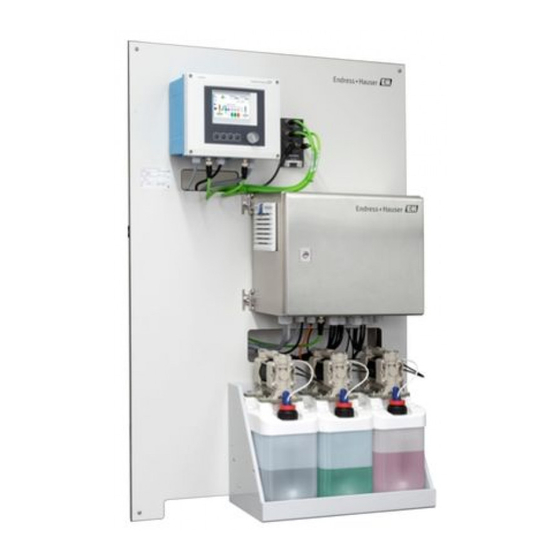
Product description Liquiline Control CDC90 Product description System structure A complete measuring system comprises the following components: • CDC90 control unit • Pneumatic control unit • Canister pump unit The system is available in different versions. Here is a complete overview comprising all of the system' s modules. -
Page 11: Overview Of Pneumatic Control Unit
Liquiline Control CDC90 Product description Overview of pneumatic control unit A0031834 2 Pneumatic control unit Pilot valve manifold, bus node Actuator terminal Compressed air Output interface terminal F1 fuse of the pneumatic control unit and CDC90 control Pressure switch... -
Page 12: Incoming Acceptance And Product
Incoming acceptance and product identification Liquiline Control CDC90 Incoming acceptance and product identification Incoming acceptance 1. Verify that the packaging is undamaged. Notify the supplier of any damage to the packaging. Keep the damaged packaging until the issue has been resolved. -
Page 13: Scope Of Delivery
Liquiline Control CDC90 Incoming acceptance and product identification 4. Enter the order code from the nameplate into the search field. Then select Show details. Details of each feature (selected option) of the order code are displayed. Scope of delivery The scope of delivery comprises: •... -
Page 14: Installation
Installation Liquiline Control CDC90 Installation Installation conditions The device is intended for wall mounting. Wall mounting as: Panel 5.1.1 Installation site Note the following when erecting the device: • Make sure that the wall has sufficient load-bearing capacity and is fully perpendicular. - Page 15 Liquiline Control CDC90 Installation 5.2.2 Dimensions of pneumatic control unit 210 (8.27) 380 (15.0) A0031929 4 Dimensions of pneumatic control unit in mm (in) 5.2.3 Dimensions of canister holder 160 (6.3) 150 (5.9) 8.5 (0.33) Ø 470 (18.50) 220 (8.66) A0033139 ...
- Page 16 Installation Liquiline Control CDC90 65 (2.56) 140 (5.51) 151 (5.94) 190 (7.48) A0032277 6 Dimensions of canister with pump in mm (in) 5.2.4 Dimensions of rinsing block 195 (7.68) 120 (4.72) 108 (4.25) 181 (7.13) 223.5 (8.80) A0032267 7 Dimensions of rinsing block PVDF, in mm (in) 132.5 (5.2)
-
Page 17: Wall Mounting
Liquiline Control CDC90 Installation 5.2.5 Dimensions of mounting plate 770 (30.31) 8 (0.31) 8 (0.31) 150 (6.00) 380 (15.00) 20 (0.79) 600 (23.62) 86 (3.39) A0031946 9 Dimensions of mounting plate in mm (in) Wall mounting CAUTION Risk of injury The weight of the unit may result in crush injuries or other injuries. -
Page 18: Maximum Hose And Cable Length For One Measuring Point
Installation Liquiline Control CDC90 Maximum hose and cable length for one measuring point In the diagram below you will see the maximum length of the hose and cable between the system components. 0.5-2* (1.64-6.56) A0032617 10 Maximum distances between the system components in m (ft) -
Page 19: Securing Rinsing Block To Assembly
Liquiline Control CDC90 Installation Securing rinsing block to assembly CAUTION Risk of injury Crush injuries or other injuries may occur. ‣ Use suitable mounting tools, for example an Allen key. Rinsing block bracket to assembly A0032669 1. Hold half of the rinsing block bracket (1) up to the assembly cylinder. -
Page 20: Mounting The Rinsing Block For The Second Measuring Point
Installation Liquiline Control CDC90 Connecting to rinsing block valve A0032739 1. Unscrew the head of the valve. 2. Remove the head and the clamping ring ferrule positioned underneath. 3. Guide the hose through the head and the clamping ring ferrule into the valve. -
Page 21: Mechanical Connection
Liquiline Control CDC90 Installation A0033445 Connect the two parts using the screws provided. Mechanical connection CAUTION Very loud pumps The noise from the pumps can hurt the ears. ‣ Wear ear protectors in the vicinity of the pumps. 5.8.1 Connecting medium and compressed air... - Page 22 Installation Liquiline Control CDC90 A0031871 12 Hose connection diagram for medium and compressed air Pumps 1-3 (I = Inlet, O = Outlet) Process valve Buffer solutions and cleaner Water connection Assembly liquid Rinsing block Compressed air Pilot valve manifold in pneumatic control unit The individual hoses are grouped together in multihoses.
- Page 23 Liquiline Control CDC90 Installation 5.8.2 Connecting compressed air supply Compressed air supply When connecting, please pay attention to the following: • The compressed air line is to be provided by the customer. • The optimum air pressure is 4 to 6 bar (58 to 87 psi).
- Page 24 Installation Liquiline Control CDC90 5.8.3 Connecting multihoses M1 air hoses from the pneumatic control unit to the rinsing block and assembly M1 connection in the pneumatic control unit The air hoses for the pilot valves are located in the hose package of the M1 multihose.
- Page 25 Liquiline Control CDC90 Installation Hose 2 CPA471/472/475 Hose 1 Upper connection Hose 2 Lower connection Connecting assembly CPA473/474 A0033220 7. Connect the hoses as follows: Hose number: Connection on assembly: Hose 1 2 on block, measuring Hose 2 3 on block, service...
- Page 26 Installation Liquiline Control CDC90 M2 connection to rinsing block 2. Connect the hoses from the pumps to the valves of the rinsing block as follows: A0033438 Hose number Function Cleaner Buffer 1 Buffer 2 M3 (second measuring point)- air hoses from the pneumatic control unit to the...
- Page 27 Liquiline Control CDC90 Installation Pilot valve Function Hose number 9, 10 Compressed air control for 8, 11 changeover valve, 2nd measuring point Assembly retraction, 2nd measuring point Compressed air control for assembly, 2nd measuring point M3 connection to changeover valve and assembly of 2nd measuring point 3.
- Page 28 Installation Liquiline Control CDC90 Connecting the rinse water When connecting the water, please pay attention to the following: • The rinse water pipe is to be provided by the customer. • The water pressure must be 3-6 bar (43.5-87 psi).
- Page 29 Liquiline Control CDC90 Installation 2. Remove the corrugated hose (outer sheathing of the multihose) from the fastener and the plug. 3. Feed the hoses and cables deeper into the corrugated hose by pulling them out at the other end. Do this up to the point where you want to shorten the corrugated hose.
-
Page 30: Post-Installation Check
Installation Liquiline Control CDC90 Pilot valve Function Hose number Pump 1 Pump 2 Pump 3 Post-installation check 1. Following installation, check all devices for damage. 2. Verify that the specified mounting distances have been observed. 3. Ensure that the temperature limits at the mounting location are observed. -
Page 31: Electrical Connection
Liquiline Control CDC90 Electrical connection Electrical connection Connection conditions NOTICE The device does not have a power switch ‣ A fuse with a maximum rating of 16 A must be provided by the customer. Observe the local regulations for installation. - Page 32 Electrical connection Liquiline Control CDC90 6.2.1 Cable gland assignment A0033181 19 CDC90 control unit cable gland Wiring Designation Assignment CDC90 control unit supply voltage Ethernet Sensor, 1st measuring point Sensor, 2nd measuring point Sensor, float switch, pressure switch, IPC power supply 6.2.2...
- Page 33 Liquiline Control CDC90 Electrical connection Slot 6 Port 1 Pin 47 128/SW Service A0031940 20 Example of port assignment 6.2.3 Opening the CDC90 control unit NOTICE Pointed or sharp tools If unsuitable tools are used, they can scratch the housing or damage the seal, and thus have a negative impact on the leak-tightness of the housing! ‣...
- Page 34 Electrical connection Liquiline Control CDC90 6.2.4 Cable mounting rail A0025171 23 Cable mounting rail and associated function Cable mounting rail Additional threaded bolts for ground connections Threaded bolt (protective ground connection, Cable clamps (fixing and grounding the sensor central grounding point) cables) 6.2.5...
- Page 35 Liquiline Control CDC90 Electrical connection 6.2.6 Cable terminals Plug-in terminals for Memosens and PROFIBUS/RS485 connections ‣ ‣ Insert the cable until the limit ‣ Press the screwdriver against Remove the screwdriver (closes stop. the clip (opens the terminal). the terminal).
- Page 36 Electrical connection Liquiline Control CDC90 Connecting the supply voltage to BASE-E – – – – – – L+ N- PE Power L/+ N/– PE L/+ N/– * A0015872 A0015873 27 Power supply connection on the BASE-E 28 Overall wiring diagram BASE-E and...
-
Page 37: Connecting The Sensors
Liquiline Control CDC90 Electrical connection NOTICE Protective ground/ground cable with end sleeve or open cable lug The cable can become loose. Loss of the protective function. ‣ To connect the protective ground or ground cable to the threaded bolt, only use a cable with a closed cable lug as per DIN 46211, 46225, form A. - Page 38 Electrical connection Liquiline Control CDC90 1. Sensor cable connected directly Connect the sensor cable to the Memosens terminal connector of the sensor module 2DS or of base module L, H or E. 2. When connecting via M12 connector Connect the sensor connector to an M12 sensor socket which has been previously installed or is supplied on delivery.
-
Page 39: Connecting Additional Inputs And Outputs
Liquiline Control CDC90 Electrical connection Connecting additional inputs and outputs WARNING Module not covered No shock protection. Danger of electric shock! ‣ If you are modifying or extending your hardware, always fill the slots from left to right. Do not leave any gaps. - Page 40 Electrical connection Liquiline Control CDC90 Connecting the DIO A0033457 1. Guide the cable for the digital inputs through cable gland "G" provided. 2. Connect the cable wires as per the wiring diagram: DIO 5 W8 cable Supply/Digital I/O Digital In 2...
- Page 41 Liquiline Control CDC90 Electrical connection 6.4.2 Current inputs Module 2AI – – 35 Module 36 Wiring diagram Input for control signal from softkeys. The second input can also be used to control the implementation of the program remotely.
-
Page 42: Connecting Digital Communication
Electrical connection Liquiline Control CDC90 Connecting digital communication 6.5.1 Connecting the Ethernet The connected external devices must be insulated against dangerous voltage that may occur. A0033466 In the CDC90 control unit, connect the Ethernet adapter cable to the ETH module A0033454 Connect the Ethernet adapter cable W24 to cable gland "5"... - Page 43 Liquiline Control CDC90 Electrical connection Connecting the Ethernet switch communication cable A0033473 1. Connect the communication cable (W22) for the Ethernet switch (1) to the connection (2). 2. Guide the cable through cable gland "4" of the pneumatic control unit. → 46 3.
- Page 44 Electrical connection Liquiline Control CDC90 Terminal XL Cable wire Brown Blue Gray LED ETH module 128/SW Service 40 Wiring 39 Module diagram LEDs on front of module Designation Color Description RJ45 LNK/ACT • Off = Connection is not active •...
-
Page 45: Connecting The Ipc
Liquiline Control CDC90 Electrical connection 6.5.2 Bus termination There are 2 ways to terminate the bus: 1. Internal termination (via DIP switch on module board) "OFF" "ON" 41 DIP switch for internal termination ‣ Using a suitable tool such as a tweezer, move all four DIP switches to the "ON" position. -
Page 46: Connecting The Pneumatic Control Unit
Electrical connection Liquiline Control CDC90 2. Connect the W9 cable to the IPC module (3) at the X5 port. (NET) (I/O Bus) Shld CANL CANH Case A0033467 Connect the W23 cable from the outside to the M12 cable gland "8" provided. - Page 47 Liquiline Control CDC90 Electrical connection Assignment Wiring Designation Not assigned Ethernet cable of valve manifold W20->W22 8th/black hose in valve manifold Not assigned M3 hoses 8, 9, 10, 11 Float switch/level cable W4, W5, W6 PWR cable of Ethernet switch...
- Page 48 Electrical connection Liquiline Control CDC90 Monitoring of assembly position A0032747 44 CPA47x compressed air control BN Ö L+ (1) OUT (2) BU Ö L- (2) IN (1) A0032777 Refer to the mark directly at the limit position switch; "1" is inlet (in), "2" is outlet (out).
- Page 49 Liquiline Control CDC90 Electrical connection Monitoring of assembly position A0033325 45 CPA47x compressed air control ‣ When setting up the connections for assembly retraction and for confirmation of position in the pneumatic control unit, please proceed as follows: Connection at output interface terminal in the pneumatic control unit...
- Page 50 Electrical connection Liquiline Control CDC90 Cleanfit CPA8x Assembly monitoring A0032753 46 Compressed air control unit CPA47... Feedback cable A0017831 Limit position switch, service position Limit position switch, measuring position Connector, M12, solder side (inside of assembly) Coding Connector, Pin side (outside of assembly) A0022163 ...
-
Page 51: Connecting The Main Supply Voltage
Liquiline Control CDC90 Electrical connection Connection at output interface terminal in the pneumatic control unit Output interface terminal T1, Cable wire Function bottom Pin 1 W2, BK Limit position switch, confirmation of position Pin 2 W2, BU Limit position switch, confirmation of... -
Page 52: Ensuring The Degree Of Protection
Electrical connection Liquiline Control CDC90 Terminal X1, bottom Cable wire L1, BN PE, GN-YE N, BU PE PE PE PE PE PE PE PE PE PE PE PE PE A0035338 48 Terminal diagram of main supply voltage of actuator terminal X1 in the pneumatic control unit... -
Page 53: Post-Connection Check
Liquiline Control CDC90 Electrical connection 6.10 Post-connection check WARNING Connection errors The safety of people and of the measuring point is under threat. The manufacturer does not accept any responsibility for errors that result from failure to comply with the instructions in this manual. -
Page 54: System Integration
System integration Liquiline Control CDC90 System integration Web server 7.1.1 Establishing the data connection 1. Start your PC. 2. First, set a manual IP address in the network connection settings of the operating system. 3. Start the Internet browser. 4. If you use a proxy server to connect to the Internet: Disable the proxy (browser settings under "Connections/LAN settings"). - Page 55 Liquiline Control CDC90 System integration Amber Blue RJ45 assignment to M12 connection RJ45 Yellow White Amber Blue More detailed information on fieldbus communication is provided on the product pages on the Internet (→ SD01518C). Endress+Hauser...
-
Page 56: Operation Options
Operation options Liquiline Control CDC90 Operation options Overview 8.1.1 Display and operating elements A0031833 49 Overview of operation Touchdisplay LED light (green = operating, red = error, white = off) Soft keys (functions can be configured) Access to the operating menu via the local display 8.2.1... - Page 57 Liquiline Control CDC90 Operation options 8.2.2 Assign soft keys The soft keys are assigned the following functions: Key combination Function (press simultaneously) 1 and 2 Switches configuration and visualization of measuring point to 1 2 and 3 Switches configuration and visualization of measuring point to 2 3 and 4 Switches "Service assembly"...
- Page 58 Operation options Liquiline Control CDC90 8.2.3 Menu overview A0033714 Item Function Date and time Error message Display and navigation to measuring point Language selection Command, fast access Overview of measuring points Navigation overview Menu path Three main menus are available to operate the device: •...
-
Page 59: Access To The Operating Menu Via The Web Browser
Liquiline Control CDC90 Operation options Item Function Main Setup menu, settings options for system and program configuration Main System menu, overview of measuring points, maintenance activities and administration Main Diagnosis menu, diagnostic list and system monitoring Submenu Back to navigation overview Access to the operating menu via the Web browser The same menu options are available via the web server as for the onsite display. -
Page 60: Commissioning
Commissioning Liquiline Control CDC90 Commissioning Function check WARNING Incorrect connection, incorrect supply voltage Safety risks for staff and device malfunctions! ‣ Check that all connections have been established correctly in accordance with the wiring diagram. ‣ Ensure that the supply voltage matches the voltage indicated on the nameplate. -
Page 61: Switching On
Liquiline Control CDC90 Commissioning A0033912 1. Unscrew the float switch. 2. Remove it together with the cover and the pump. 3. Now fill the empty canister or replace it with a full one. Use a funnel when filling the canister. - Page 62 Commissioning Liquiline Control CDC90 9.3.2 Setting date and time A0033834 51 Selecting system time 1. Press System time setting in the top menu bar. 2. Set the date and time in accordance with your desired time zone. 9.3.3 Start screen The Start overview is used for monitoring and operation.
- Page 63 Liquiline Control CDC90 Commissioning To return to the start screen, go to Menu/System/Meas. point overview. 9.3.4 Service operating mode During commissioning, the mode must be set to Service . 1. In the menu, go to Menu/Setup/Settings. 2. For Operating mode switch to Service.
- Page 64 Commissioning Liquiline Control CDC90 9.3.8 Configuring program parameters The system comprises preconfigured programs and program steps for the purpose of monitoring, cleaning or validating the measuring points. These can be extended or regenerated. The existing program steps should be configured during commissioning.
-
Page 65: Operation
Liquiline Control CDC90 Operation Operation 10.1 Measuring mode 10.1.1 Measured values A0033715 Item Function Measured value Temperature Program step name/ID/remaining time Program name Path:Menu/System/Meas. point overview/Meas. values Function Info Meas. values Measuring menu 1 Display of • Primary value e.g. pH and temperature •... -
Page 66: Settings
Operation Liquiline Control CDC90 10.1.2 Measuring point A0033716 Position Function Program ID Program step - remaining time Measured value and temperature display Rinsing block valve Pilot valves, lit green during operation Compressed air Canister indicator, indicating residual volume in liters... - Page 67 Liquiline Control CDC90 Operation Path:Menu/Setup/Settings Function Options Info Only visible if the operating mode is set to Auto Operating mode Factory setting The mode relates to the program in • Auto. mode question. • Manual mode If the programs are set to Auto. mode •...
- Page 68 Operation Liquiline Control CDC90 Path:Menu/Setup/Settings Function Options Info Cal. meas. value Factory setting Specify measured value • Undefined • pH • ORP mV • ORP % • Temperature Factory setting If 2 Pt. calibrationselected: Buffer 1 ...2 Please insert the values in CM44 calibration setting.
-
Page 69: Configuring The System
Rinsing with water Meas. Moving to measure position ID 10 can be freely edited. All programs can be modified or optimized. Standard buffer 1 is Endress+ Hauser' s 7 pH buffer. Standard buffer 2 is Endress+Hauser' s 4 pH buffer. Endress+Hauser... - Page 70 Operation Liquiline Control CDC90 10.3.2 Generating the program Path:Menu/Setup/Program Function Info Program Selection list of programs consisting of program steps. The program steps can be edited in this menu. Program name Enter or change the program name Program step You can use this menu to edit the Program step list in a program...
- Page 71 Liquiline Control CDC90 Operation Name Function Cleaner Controls pump 1: cleaner connected Water Opens water valve H2O + Service Pos. Sealing water: Opens water valve Assembly moves to service position H2O + Meas. Item Sealing water: Opens water valve Assembly moves to measure position...
- Page 72 Operation Liquiline Control CDC90 Path:Menu/Setup/Program step Function Options Info Settings Pilot Valve Selection Default setting: • Used pilot valve Used pilot valve • Assemb. control Shuts down the program step • Assembly meas. pos. Assemb. control • Assembly service pos.
- Page 73 Liquiline Control CDC90 Operation Path:Menu/Setup/Program step Function Options Info Sterilisation Select with checkbox The program step is used for sterilization. Important for data analysis and system monitoring. Cleaning Select with checkbox The program step is used for cleaning. Important for data analysis and system monitoring.
- Page 74 Operation Liquiline Control CDC90 batch is exposed to extreme temperatures (up to 40 °C) and the park time is longer than 2 days. This procedure helps protect the sensor from drying out. Name Duration in seconds Service position Water Buffer 7 Example 1-point validation or 1-point verification This program is used to verify the measurement.
- Page 75 Endress+Hauser temperature table into account. Requests the system to perform the measurement with an E+H 9, 18 pH buffer, taking the Endress+Hauser temperature table into account. Requests the system to perform the measurement with an E+H 10 pH buffer, taking the Endress+Hauser temperature table into account.
- Page 76 Operation Liquiline Control CDC90 Name Duration in seconds Start 1Pt.cal pH Water Cleaner Wait Cleaning end Buffer 7 Wait Buffer 1 end Meas. E+H 4.00 F Water Adjustment example: In this example, a cleaning program is extended to become an adjustment program.
- Page 77 Liquiline Control CDC90 Operation 10.3.4 Limit values Limit value setting for sensor Path:Menu/Setup/Limit setting/Sensor Function Options Info Limit control Selection In this menu, you can switch on or off the Limit • OFF control . • ON Factory setting Warning regenerations Warning limit for regenerations.
- Page 78 Operation Liquiline Control CDC90 10.3.5 System configuration Path:Menu/System Settings Function Info Number Enter measuring point number Name of measuring point ATEX Specify whether the measuring point is located in an explosion-proof area. Connected sensor pH glass; pH Isfet; ORP; pH ORP: default value...
- Page 79 Liquiline Control CDC90 Operation Pump The pumps are activated via the System Settingsmenu. The pilot valves are configured here. Path:Menu/System Settings/Pump Function Options Info Pump type Factory setting Pneumatic or electric Pneumatic Pilot valve Slot Factory setting Enter the slot of the pilot valves here if you have more than one.
- Page 80 Operation Liquiline Control CDC90 Assembly Path:Menu/System Settings/Assembly Function Options Info Type Factory setting The device functions with two assembly types: 87x series. • 47X series • 87x series. Pilot valve Slot Factory setting Select slot in pilot valve manifold Remote IO type...
- Page 81 Liquiline Control CDC90 Operation Path:Menu/System Settings/Communication Function Options Info Factory setting 2.00 to 12.00 Temperature Factory setting 10.00 to 45.00 Temperature Options Temperature specification in: • Degrees Celsius • Celsius • Kelvin • Kelvin • Degrees Fahrenheit • Fahrenheit Factory setting...
-
Page 82: Calibration
Operation Liquiline Control CDC90 10.4 Calibration • Sensors with Memosens protocol are calibrated at the factory. • Users must decide whether the process conditions present require calibration during initial commissioning. • Additional calibration is not required in many standard applications. - Page 83 Liquiline Control CDC90 Operation Menu/Setup/Outputs/Current output x:y Function Options Info Current output Options Use this function to activate or deactivate a • Off variable being output at the current output • On Factory setting Source of data Options The sources of data on offer depend on your •...
- Page 84 Operation Liquiline Control CDC90 Source of data Measured value Oxygen (amp.) Selection • Temperature Oxygen (opt.) • Partial pressure • Concentration liquid • Saturation • Raw value nA (only Oxygen (amp.)) • Raw value μs (only Oxygen (opt.)) Cond i Selection •...
- Page 85 Liquiline Control CDC90 Operation Outputting the controller manipulated variable via the current output Unipolar+ Assign to the output to which an actuator that can increase the measured value is connected. Unipolar- Assign to the output to which an actuator that can decrease the measured value is connected.
- Page 86 Operation Liquiline Control CDC90 Outputting the manipulated variable of a controller To output a controller manipulated variable via a relay, the relay is modulated. The relay is energized (pulse, t ) and is then de-energized (interval, t Function = Controller...
- Page 87 Liquiline Control CDC90 Operation Function = Controller Function Options Info Actuator type Selection Here you specify what part of the controller • None should power the relay. Unipolar(+) is the part • Unipolar(-) of the manipulated variable which the controller •...
- Page 88 Operation Liquiline Control CDC90 Function = Diagnostics Function Options Info Operating mode Selection as assigned • as assigned If this option is selected, the diagnostic messages • Namur M which you have individually assigned to the relay • Namur S are output via the relay.
- Page 89 Liquiline Control CDC90 Operation Configuration of binary outputs Menu/Setup/Outputs/Binary output x:y Function Options Info Binary output Selection Switches the output on/off • Off • On Factory setting ‣ Signal type Selection Select the signal type. • Static signal Static signal •...
- Page 90 Operation Liquiline Control CDC90 Menu/Setup/Outputs/Binary output x:y Function Options Info Source of data Selection Source, whose value should be read out as a • None frequency over the binary output. • Sensor inputs • Binary inputs • Controller • Fieldbus signals •...
-
Page 91: Diagnostics And Troubleshooting
Liquiline Control CDC90 Diagnostics and troubleshooting Diagnostics and troubleshooting 11.1 Overview of diagnostic information 11.1.1 Device-specific, general diagnostic messages To call up the error list, select: Path: Menu/DIAG/Diagnosis list Item Error message Troubleshooting The time for implementing the program step has been exceeded. - Page 92 Diagnostics and troubleshooting Liquiline Control CDC90 Item Error message Troubleshooting Invalid measured value Check sensor power supply. Restart device under Setup/Diagnosis/ Reset. ‣ Measured value not available. Check connection between sensor and transmitter. Delta slope warning, measurement Check sensor, replace if necessary.
- Page 93 Liquiline Control CDC90 Diagnostics and troubleshooting Item Error message Troubleshooting ‣ Invalid data entry in calibration Check buffer values and limit values of settings. calibration results. Invalid data entry ‣ Unstable measured values. Ensure that the process is stable. Repeat the calibration.
- Page 94 Diagnostics and troubleshooting Liquiline Control CDC90 Item Error message Troubleshooting ‣ Alarm limit for delivery volume of Replace the pump. pump 3 reached. High-current consumption of pump unit Level error: Canister empty Replace the pump. Replace the canister. Disable canisters that are not being used.
-
Page 95: Monitoring The System
Liquiline Control CDC90 Diagnostics and troubleshooting 11.2 Monitoring the system The device gives you the option of monitoring the system. All configured functions can be read here. ‣ Go to Menu/DIAG/Monitoring. Path:Menu/DIAG/Monitoring Function Sensor Operation time No. of calibrations Last Calibration... -
Page 96: Maintenance
Maintenance Liquiline Control CDC90 Maintenance WARNING Process pressure and temperature, contamination, electrical voltage Risk of serious or fatal injury ‣ If the sensor has to be removed during maintenance work, avoid hazards posed by pressure, temperature and contamination. ‣ Make sure the device is de-energized before you open it. - Page 97 Liquiline Control CDC90 Maintenance 12.1.1 Pneumatic control unit Weekly Annually Check compressed air connections Check if interior is clean, dry and free from corrosion. for leaks: • Clean and dry the interior. • Pilot valves • Check seals, couplings and pumps for leaks and damage.
- Page 98 Maintenance Liquiline Control CDC90 disassembling the assembly, replacing the sensors and seals, and contains information on the material resistance properties, as well as on spare parts and accessories. Weekly Annually Check the upper part of the Clean the exterior of the assembly as required. To replace the seal, assembly for impermeability the assembly must be clean, dry and if necessary decontaminated.
- Page 99 Liquiline Control CDC90 Maintenance 12.1.5 Cables, connections and power supply lines Weekly Monthly Biannually ‣ Check the impermeability If the assembly is Check if the interior and circuit boards located in a damp are clean, dry and free from corrosion.
-
Page 100: Repairs
Repairs Liquiline Control CDC90 Repairs 13.1 General notes ‣ Only use spare parts from Endress + Hauser to guarantee the safe and stable functioning of the device. Detailed information on the spare parts is available at: www.endress.com/device-viewer ‣ Following repairs, check that the device is complete, in a safe condition and functioning correctly. - Page 101 Liquiline Control CDC90 Repairs Item Order no. Kit CDC90 air filter 71361218 Kit CDC90 wall holder unit 71361219 Kit CDC90 couplings 71361220 Kit CDC90 8-valve manifold 71361221 Kit CDC90 16-valve manifold 71361222 Kit CDC90 valve module x 2 (NC) 71361223...
-
Page 102: Return
The product must be returned if repairs or a factory calibration are required, or if the wrong product was ordered or delivered. As an ISO-certified company and also due to legal regulations, Endress+Hauser is obliged to follow certain procedures when handling any returned products that have been in contact with medium. - Page 103 Liquiline Control CDC90 Accessories Cleanfit CPA472 • Compact plastic retractable assembly for installation in tanks and pipes • For manual or pneumatic, remote-controlled operation • Product Configurator on the product page: www.endress.com/cpa472 Technical Information TI00223C Cleanfit CPA472D • Robust retractable assembly for pH, ORP and other industrial sensors •...
-
Page 104: Sensors
Accessories Liquiline Control CDC90 14.2 Sensors 14.2.1 Glass electrodes Orbisint CPS11D • pH electrode for process technology • Optional SIL version for connecting to SIL transmitter • With dirt-repellent PTFE diaphragm • Product Configurator on the product page: www.endress.com/cps11d Technical Information TI00028C Memosens CPS31D •... - Page 105 Liquiline Control CDC90 Accessories Ceragel CPS72D • ORP electrode with reference system including ion trap • Product Configurator on the product page: www.endress.com/cps72d Technical Information TI00374C Orbipac CPF82D • Compact ORP sensor for installation or immersion operation in process water and wastewater •...
-
Page 106: Additional Functionality
Accessories Liquiline Control CDC90 Memosens CPS96D • Combined pH/ORP sensor for chemical processes • With poison-resistant reference with ion trap • With Memosens technology • Product Configurator on the product page: www.endress.com/cps96d Technical Information TI00507C 14.3 Additional functionality 14.3.1 Hardware extension modules Kit, extension module 2AI •... - Page 107 • Order No. 71092051 14.4.5 Buffer solutions High-quality buffer solutions from Endress+Hauser - CPY20 The secondary buffer solutions have been referenced to primary reference material of the PTB (German Federal Physico-technical Institute) or to standard reference material of NIST (National Institute of Standards and Technology) according to DIN 19266 by a laboratory accredited by the DAkkS (German accreditation body) according to DIN 17025.
-
Page 108: Technical Data
Technical data Liquiline Control CDC90 Technical data 15.1 Input Measured values → Documentation of the connected sensor Measuring ranges → Documentation of the connected sensor Types of input • Digital sensor inputs for sensors with Memosens protocol • Digital inputs (optional) -
Page 109: Output
Liquiline Control CDC90 Technical data 15.4 Output Output signal IPC output signals Ethernet Modbus TCP EtherNet/IP PROFIBUS PROFINET DP (via (via fieldbus fieldbus coupler) coupler) Signal encoding IEEE 802.3 IEEE 802.3 IEEE 802.3 PRIBUS-DP- IEEE 802.3 (Ethernet) (Ethernet) (Ethernet) compliant as... -
Page 110: Current Outputs, Active
Technical data Liquiline Control CDC90 Cable specification Max. 2.5 mm (14 AWG) 15.6 Current outputs, active Span 0 to 23 mA 2.4 to 23 mA for HART communication Signal characteristic Linear Electrical specification Output voltage Max. 24 V Test voltage 500 V 15.7... -
Page 111: Power Supply
Liquiline Control CDC90 Technical data EtherNet switch Name EtherNet/IP adapter Manufacturer 3S-Smart Software Solutions GmbH Categories EtherNet/IP local adapter EtherNet/IP ODVA certification Device profile Generic device Manufacturer ID 1285 Device type ID 0000 1016 Polarity Auto-MIDI-X Minimum RPI 300 ms (default) -
Page 112: Performance Characteristics
Technical data Liquiline Control CDC90 15.9 Performance characteristics Response time Current outputs = max. 500 ms for an increase from 0 to 20 mA Current inputs = max. 330 ms for an increase from 0 to 20 mA Digital inputs and outputs = max. -
Page 113: 15.11 Mechanical Construction
Liquiline Control CDC90 Technical data Electromagnetic Interference emission and interference immunity as per EN 61326-1:2013, Class A for compatibility Industry Electrical safety IEC 61010-1, Class I equipment Low voltage: overvoltage category II Environment < 2000 m (< 6562 ft) above MSL Max. - Page 114 Technical data Liquiline Control CDC90 Device Material Pump canister unit Pump PVDF+CF/PP/NBR+PTFE/PTFE/PP Canister Float switch PVC/EPDM/PE Canister fitting ABS/PMMA Bracket M5 L110*B40 W8 O-ring EPDM Coupling DMG/8*6 1/4 PVDF Canister shelf Rinsing block Process valve EPDM/PP/stainless steel:1.4408/PTFE Rinsing body PVDF/1.4401...
-
Page 115: Index
Liquiline Control CDC90 Index Index Declaration of Conformity ..... 13 Degree of protection ......112 Accessories . - Page 116 Index Liquiline Control CDC90 Program steps ......70 Protocol-specific data ..... . . 110 Maintenance .
- Page 117 Liquiline Control CDC90 Index Warnings ........5 Water pipe .
- Page 118 www.addresses.endress.com...