Table of Contents
Advertisement
Quick Links
KA01238C/07/EN/04.17
71391615
Products
Brief Operating Instructions
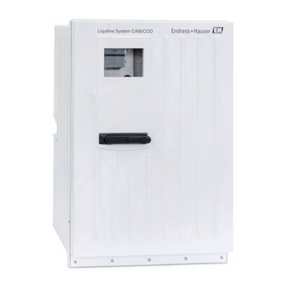
Liquiline System CA80COD
Colorimetric analyzer for chemical oxygen demand
These Instructions are Brief Operating Instructions; they are
not a substitute for the Operating Instructions pertaining to
the device.
Detailed information on the device can be found in the
Operating Instructions and in the other documentation
available at:
• www.endress.com/device-viewer
• Smart phone/tablet: Endress+Hauser Operations App
Detailed information on the device can be found in the
Operating Instructions and in the other documentation
available on the CD.
Solutions
Services
Advertisement
Table of Contents

Related Manuals for Endress+Hauser CA80COD


Summary of Contents for Endress+Hauser CA80COD
- Page 1 Detailed information on the device can be found in the Operating Instructions and in the other documentation available at: • www.endress.com/device-viewer • Smart phone/tablet: Endress+Hauser Operations App Detailed information on the device can be found in the Operating Instructions and in the other documentation available on the CD.
- Page 2 Liquiline System CA80COD Order code: XXXXX-XXXXXX Ser. no.: XXXXXXXXXXXX Ext. ord. cd.: XXX.XXXX.XX Serial number www.endress.com/deviceviewer Endress+Hauser Operations App A0023555 Endress+Hauser...
-
Page 3: Table Of Contents
Liquiline System CA80COD Table of contents Table of contents Document information ............4 Warnings . -
Page 4: Document Information
Document information Liquiline System CA80COD Document information Warnings Structure of information Meaning This symbol alerts you to a dangerous situation. DANGER Failure to avoid the dangerous situation will result in a fatal or serious injury. Causes (/consequences) If necessary, Consequences of non- compliance (if applicable) ‣... -
Page 5: Symbols At The Device
Liquiline System CA80COD Document information Symbols at the device Symbol Meaning Reference to device documentation Caution: Hazardous voltage Warning: Health hazard Warning: Oxidizing Warning: Acute toxicity Warning: Corrosive Warning: Hazardous to the aquatic environment Endress+Hauser... -
Page 6: Documentation
Liquiline System CA80COD Documentation The following instructions complement these Brief Operating Instructions and are available on the product pages on the internet: • Operating Instructions for Liquiline System CA80COD – Device description – Commissioning – Operation – Software description (excluding sensor menus; these are described in a separate manual - see below) –... -
Page 7: Basic Safety Instructions
Designated use The Liquiline System CA80COD is a wet-chemical analyzer for the almost continuous determination of the chemical oxygen demand (COD) of liquid media. The analyzer is designed for use in the following applications: •... -
Page 8: Product Safety
Basic safety instructions Liquiline System CA80COD If faults cannot be rectified, products must be taken out of service and protected against unintentional operation. Keep this door closed when not carrying out service and maintenance work. CAUTION Analyzer in operation and during maintenance activities Risk of injury and infection from medium or reagents ‣... -
Page 9: Incoming Acceptance And Product Identification
Liquiline System CA80COD Incoming acceptance and product identification Incoming acceptance and product identification Incoming acceptance Verify that the packaging is undamaged. Notify your supplier of any damage to the packaging. Keep the damaged packaging until the matter has been settled. -
Page 10: Scope Of Delivery
Incoming acceptance and product identification Liquiline System CA80COD 3.2.2 Product identification Product page www.endress.com/ca80cod Interpreting the order code The order code and serial number of your product can be found in the following locations: • On the nameplate • In the delivery papers Obtaining information on the product Go to the product page for your product on the Internet. - Page 11 Liquiline System CA80COD Incoming acceptance and product identification 3.4.2 The product has been certified according to guidelines TP TC 004/2011 and TP TC 020/2011 which apply in the European Economic Area (EEA). The EAC conformity mark is affixed to the product.
-
Page 12: Installation
Installation Liquiline System CA80COD Installation CAUTION Incorrect transportation or installation can cause injury and damage the device ‣ Always use a lifting truck or a fork-lift to transport the analyzer. Two people are needed for the installation. ‣ Lift the device by the recessed grips. - Page 13 Liquiline System CA80COD Installation 417 (16.42) 530 (20.87) A0030419 2 Liquiline System CA80 open version, dimensions in mm (in) Endress+Hauser...
- Page 14 Installation Liquiline System CA80COD 654 (25.74) A0028821 3 Liquiline System CA80 with base, dimensions in mm (in) Endress+Hauser...
- Page 15 Liquiline System CA80COD Installation Ø 7 (0.28) 96 (3.78) 118 (4.65) A0030527 4 Dimensions of the Y strainer. Engineering unit mm (in) 4.1.3 Installation site Note the following when erecting the device: • Make sure that the wall has sufficient load-bearing capacity and is fully perpendicular.
-
Page 16: Mounting The Analyzer On A Wall
Installation Liquiline System CA80COD Mounting the analyzer on a wall ≥ 330(12.99) ≤ 116 ° A0028814 6 Maximum opening angle A0028811 5 Minimum spacing required for mounting. Engineering unit mm (in). Mounting materials for securing the device to the wall (screws, wall plugs) are not included in the delivery and must be provided by the client. - Page 17 Liquiline System CA80COD Installation Ø 11 (0.43) Ø 10.7 (0.42) 120 (4.72) A0028810 8 Securing the holder unit on the housing 7 Holder unit dimensions. Engineering unit mm (inch) Endress+Hauser...
- Page 18 Installation Liquiline System CA80COD A0028812 9 Hooking into the wall holder unit Hook the analyzer into the wall holder unit. Secure the two top parts of the wall holder unit with the screw supplied. Endress+Hauser...
-
Page 19: Mounting The Analyzer On A Base
Liquiline System CA80COD Installation Mounting the analyzer on a base 624 (24.57) 530 (20.87) A0028809 10 Foundation plan Fasteners (4 x M10) Dimensions of Liquiline System CA80 Endress+Hauser... -
Page 20: Mounting The Y Strainer (Optional)
Installation Liquiline System CA80COD A0028817 11 Securing the base Screw the base to the ground. Have two people lift the analyzer and place it on the base. Use the recessed grips. Screw the base to the analyzer using the 6 screws supplied. -
Page 21: Post-Installation Check
Liquiline System CA80COD Installation Apply the glue evenly (closed adhesive layer) to the adhesive surfaces (first sleeve, then pipe). Join the parts together immediately (screw them together as far as possible). Remove any surplus glue. Allow the glued parts to harden for at least 24 hours before exposing the system to sample. -
Page 22: Electrical Connection
Electrical connection Liquiline System CA80COD Electrical connection WARNING Device is live Incorrect connection may result in injury or death ‣ The electrical connection may be performed only by an electrical technician. ‣ The electrical technician must have read and understood these Operating Instructions and must follow the instructions contained therein. - Page 23 Liquiline System CA80COD Electrical connection Using a Torx screwdriver (T25), release the five screws on the carrier board (3) and fold out the board towards the front. Using a Phillips head screwdriver, release the six screws on the electronics compartment cover (4) and fold out the cover towards the front.
-
Page 24: Connecting The Sensors And Additional Modules
Electrical connection Liquiline System CA80COD Route the cables on the rear panel of the device so that they are properly protected. Cable glands are available for the cable entry. A0030460 Cable glands In the case of order versions with G' and NPT cable glands, the pre-mounted cable glands with an M‐thread must be replaced by the G' or NPT glands enclosed. - Page 25 Liquiline System CA80COD Electrical connection A0030429 Screws of electronics compartment cover BASE-E A0028935 13 Connection compartment in the controller housing E basic module Analyzer interface Dummy cover Module cover Endress+Hauser...
- Page 26 Electrical connection Liquiline System CA80COD E basic module 24 VDC Power A0016535 14 E basic module Indicator LEDs Slot for display cable Voltage connection Service interface Alarm relay connection Connections for 2 Memosens sensors (optional) Power supply for digital fixed cable sensors...
- Page 27 Liquiline System CA80COD Electrical connection 85 86 24VDC Alarm Sensor supply Power – (internal) – – 0/4 ... 20 mA Display Service HART – Sensor A0016537 15 E basic module wiring diagram 5.2.2 Connecting the sensors Only use terminated genuine cables where possible.
- Page 28 Electrical connection Liquiline System CA80COD Ground the outer shield of the cable via the metal gland under the E basic module. A0028930 17 Terminal strip 5.2.3 Connecting additional inputs, outputs or relays WARNING Module not covered No shock protection. Danger of electric shock! ‣...
- Page 29 Liquiline System CA80COD Electrical connection Digital inputs and outputs DIO module – – – – – – 18 Module 19 Wiring diagram Current inputs 2AI module – – 20 Module 21 Wiring diagram Endress+Hauser...
- Page 30 Electrical connection Liquiline System CA80COD Current outputs – – – – – – 22 Module 23 Wiring 24 Module 25 Wiring diagram diagram Relay 2R module 4R module 29 Wiring 26 Module 27 Wiring ...
- Page 31 Liquiline System CA80COD Electrical connection 5.2.4 Connecting digital communication Module 485 128/SW Service DGND Termi- nation RS485 31 Wiring 30 Module diagram Terminal PROFIBUS DP Modbus RS485 Not connected DGND DGND Endress+Hauser...
- Page 32 Electrical connection Liquiline System CA80COD LEDs on front of module Description Color Description RJ45 LNK/ACT • Off = Connection is not active • On = Connection is active • Flashing = Data transmission RJ45 10/100 • Off = Transmission rate 10 MBit/s •...
- Page 33 Liquiline System CA80COD Electrical connection Module ETH 128/SW Service 33 Wiring 32 Module diagram LEDs on front of module Designation Color Description RJ45 LNK/ACT • Off = Connection is not active • On = Connection is active • Flashing = Data transmission...
-
Page 34: Hardware Settings
Electrical connection Liquiline System CA80COD Hardware settings 5.3.1 Bus termination (module 485 only) There are two ways to terminate the bus: 1. Internal terminating resistor (via DIP switch on the module board) "OFF" "ON" 34 DIP switches for internal terminating resistor ‣... -
Page 35: Ensuring The Degree Of Protection
Liquiline System CA80COD Electrical connection Set the desired bus address via the DIP switches of module 485. For PROFIBUS DP, valid bus addresses are anything between 1 and 126, and anything between 1 and 247 for Modbus. If you configure an invalid address, software addressing is automatically enabled via the local configuration or via the fieldbus. -
Page 36: Post-Connection Check
Operation options Liquiline System CA80COD Post-connection check WARNING Connection errors The safety of people and of the measuring point is under threat. The manufacturer does not accept any responsibility for errors that result from failure to comply with the instructions in this manual. - Page 37 Liquiline System CA80COD Operation options 6.1.2 Display Menu path and/or device designation Status display Assignment of the soft keys, e.g. ESC: escape or abortion of a sampling process MODE: quick access to frequently required functions DIAG: link to Diagnostics menu...
-
Page 38: Access To The Operating Menu Via The Local Display
Operation options Liquiline System CA80COD Access to the operating menu via the local display 6.2.1 Operating concept MENU MODE DIAG HOLD MODE DIAG Pressing the soft key: selecting the menu directly Turning the navigator: moving the cursor in the menu... -
Page 39: Configuration Options
Liquiline System CA80COD Operation options 6.2.2 Locking or unlocking operating keys Locking operating keys Press the navigator for longer than 2 s. A context menu for locking the operating keys is displayed. You have the choice of locking the keys with or without password protection. "With password"... - Page 40 Operation options Liquiline System CA80COD 6.3.3 Numerical values • You are changing a variable. • The maximum and minimum values for this variable are shown on the display. • Set a value within this range. • Example: Menu/Operation/Display/Contrast 6.3.4 Actions •...
- Page 41 Liquiline System CA80COD Operation options 6.3.5 Free text • You are assigning an individual designation. • Enter a text. You can use the characters in the editor for this purpose (upper-case and lower-case letters, numbers and special characters). • Using the soft keys, you can: –...
-
Page 42: Commissioning
Commissioning Liquiline System CA80COD 6.3.6 Tables • Tables are needed to map mathematical functions . • You edit a table by navigating through rows and columns with the navigator and changing the values of the cells. • You only edit the numerical values. The controller automatically takes care of the engineering units. - Page 43 Liquiline System CA80COD Commissioning CAUTION Analyzer in operation and during maintenance activities Risk of injury and infection from medium or reagents ‣ Before hoses are released make sure that no action, such as the pumping of sample, is currently running or is due to start soon.
-
Page 44: Function Check
Commissioning Liquiline System CA80COD Hose connection diagram A0028827 41 Liquiline System CA80COD Sample Procedure Dilution module (optional) Zero standard 0 Water for optional dilution module Reagent RN Reagent RK Reagent RB Standard 1 Ventilation Dosing system Pressure reactor Function check... -
Page 45: Switching On The Measuring Device
Liquiline System CA80COD Commissioning WARNING Connection errors The safety of people and of the measuring point is under threat. The manufacturer does not accept any responsibility for errors that result from failure to comply with the instructions in this manual. - Page 46 Commissioning Liquiline System CA80COD Return to measuring mode by pressing and holding the soft key for ESC for at least one second. Your analyzer now works with your basic settings. The sensors connected use the factory settings of the sensor type in question and the individual calibration settings that were last saved.
- Page 48 *71391615* 71391615 www.addresses.endress.com...