Endress+Hauser Liquiline Control CDC90 Brief Operating Instructions
Automated cleaning and calibration of memosens sensors
Hide thumbs
Also See for Liquiline Control CDC90:
- Operating instructions manual (118 pages) ,
- Brief operating instructions (76 pages) ,
- Operating instructions manual (16 pages)
Table of Contents
Advertisement
Quick Links
KA01306C/07/EN/04.19
71461881
2019-12-11
Products
Brief Operating Instructions
Liquiline Control CDC90
Automated cleaning and calibration of Memosens
sensors
These instructions are Brief Operating Instructions; they are
not a substitute for the Operating Instructions pertaining to
the device.
Detailed information on the device can be found in the
Operating Instructions and in the other documentation
available at:
• www.endress.com/device-viewer
• Smart phone/tablet: Endress+Hauser Operations App
Solutions
Services
Advertisement
Table of Contents

Related Manuals for Endress+Hauser Liquiline Control CDC90


Summary of Contents for Endress+Hauser Liquiline Control CDC90
- Page 1 These instructions are Brief Operating Instructions; they are not a substitute for the Operating Instructions pertaining to the device. Detailed information on the device can be found in the Operating Instructions and in the other documentation available at: • www.endress.com/device-viewer • Smart phone/tablet: Endress+Hauser Operations App...
- Page 2 Liquiline Control CDC90 Order code: XXXXX-XXXXXX Ser. no.: XXXXXXXXXXXX Ext. ord. cd.: XXX.XXXX.XX Serial number www.endress.com/deviceviewer Endress+Hauser Operations App A0023555 Endress+Hauser...
-
Page 3: Table Of Contents
Liquiline Control CDC90 Table of contents Table of contents About this document ............. . 5 Warnings . - Page 4 Table of contents Liquiline Control CDC90 Configuring the measuring device ............70...
-
Page 5: About This Document
Liquiline Control CDC90 About this document About this document Warnings Structure of information Meaning This symbol alerts you to a dangerous situation. DANGER Failure to avoid the dangerous situation will result in a fatal or serious injury. Causes (/consequences) If necessary, Consequences of non- compliance (if applicable) ‣... -
Page 6: Symbols On The Device
Reference to device documentation Documentation The following manuals which are available on the product pages on the internet complement these Operating Instructions: • Operating Instructions for Liquiline Control CDC90 • Device description • Commissioning • Operation • Software description (excluding sensor menus; these are described in a separate manual - see below) •... -
Page 7: Basic Safety Instructions
Designated use The Liquiline Control CDC90, used in conjunction with a Liquiline CM44, is a fully automatic measuring, cleaning and calibration system for Memosens sensors. The system is fully equipped with power supply cables and a hose system. - Page 8 Basic safety instructions Liquiline Control CDC90 Label damaged products as defective. During operation: ‣ If faults cannot be rectified: products must be taken out of service and protected against unintentional operation. CAUTION Cleaning not switched off during calibration or maintenance activities Risk of injury due to medium or cleaning agent! ‣...
-
Page 9: Product Safety
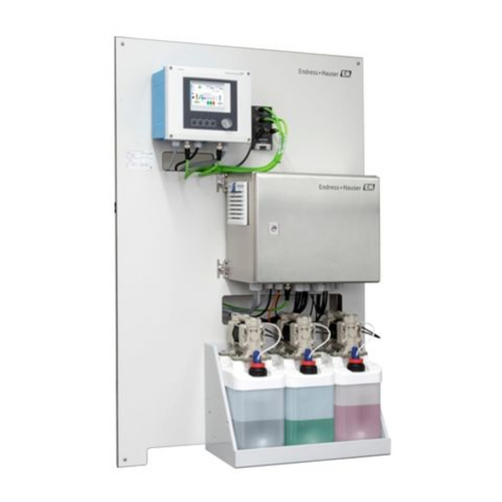
Liquiline Control CDC90 Product description Product safety 2.5.1 State-of-the-art technology The product is designed to meet state-of-the-art safety requirements, has been tested, and left the factory in a condition in which it is safe to operate. The relevant regulations and European standards have been observed. - Page 10 Product description Liquiline Control CDC90 A0032271 1 Overview of CDC90 CDC90 control unit Canister with buffer solutions and cleaner Mounting plate Canister holder EtherNet switch Float switch Pneumatic control unit Pumps Endress+Hauser...
-
Page 11: Overview Of Pneumatic Control Unit
Liquiline Control CDC90 Product description Overview of pneumatic control unit A0031834 2 Pneumatic control unit Pilot valve manifold, bus node Actuator terminal Compressed air Output interface terminal F1 fuse of the pneumatic control unit and CDC90 control unit Pressure switch... -
Page 12: Incoming Acceptance And Product Identification
Incoming acceptance and product identification Liquiline Control CDC90 Incoming acceptance and product identification Incoming acceptance Verify that the packaging is undamaged. Notify the supplier of any damage to the packaging. Keep the damaged packaging until the issue has been resolved. -
Page 13: Scope Of Delivery
Liquiline Control CDC90 Incoming acceptance and product identification Obtaining information on the product Open the product website. At the top of the page, select the link Product tools. An additional sidebar opens up. Select Online Tools followed by Access device specific information. -
Page 14: Installation
Installation Liquiline Control CDC90 Installation Installation conditions The device is intended for wall mounting. Wall mounting as: Panel 5.1.1 Installation site Note the following when erecting the device: Make sure that the wall has sufficient load-bearing capacity and is fully perpendicular. -
Page 15: Dimensions
Liquiline Control CDC90 Installation Dimensions 5.2.1 Dimensions of CDC90 control unit Ø9 (0.35) 199 (7.38) 128 (5.04) 95 (3.74) 237 (9.33) A0012396 3 Dimensions of field housing in mm (inch) Endress+Hauser... - Page 16 Installation Liquiline Control CDC90 5.2.2 Dimensions of pneumatic control unit 210 (8.27) 380 (15.0) A0031929 4 Dimensions of pneumatic control unit in mm (in) Endress+Hauser...
- Page 17 Liquiline Control CDC90 Installation 5.2.3 Dimensions of canister holder 160 (6.3) 150 (5.9) 8.5 (0.33) Ø 470 (18.50) 220 (8.66) A0033139 5 Dimensions of canister holder in mm (in) Endress+Hauser...
- Page 18 Installation Liquiline Control CDC90 65 (2.56) 140 (5.51) 151 (5.94) 190 (7.48) A0032277 6 Dimensions of canister with pump in mm (in) 5.2.4 Dimensions of rinsing block and changeover valve 195 (7.68) 120 (4.72) 108 (4.25) 181 (7.13) 223.5 (8.80) A0032267 ...
- Page 19 Liquiline Control CDC90 Installation 132.5 (5.2) 149 (5.87) A0033402 8 Dimensions of changeover valve, second measuring point in mm (in) 5.2.5 Dimensions of mounting plate 770 (30.31) 8 (0.31) 8 (0.31) 150 (6.00) 380 (15.00) 20 (0.79) 86 (3.39) 600 (23.62)
-
Page 20: Wall Mounting
Installation Liquiline Control CDC90 Wall mounting CAUTION Risk of injury The weight of the unit may result in crush injuries or other injuries. ‣ Have two people mount the unit and always use a suitable mounting tool. The size of the drill holes in the wall depends on the wall plugs used. The wall plugs and screws must be provided by the customer. -
Page 21: Multihose Bracket
Liquiline Control CDC90 Installation 0.5-2* (1.64-6.56) A0032617 10 Maximum distances between the system components in m (ft) when using the multihoses supplied as standard depending on multihose version ordered The maximum length of the multihose is 10 m (32.8 ft). See also → 35 NOTICE The canisters are higher than the rinsing block. -
Page 22: Securing The Rinsing Block To The Assembly
Installation Liquiline Control CDC90 A0034409 11 Multihose bracket ‣ Screw the multihose bracket onto the wall with washers as shown in the graphic. Securing the rinsing block to the assembly CAUTION Risk of injury Crush injuries or other injuries may occur. - Page 23 Liquiline Control CDC90 Installation Rinsing block to rinsing block bracket A0032672 ‣ Secure the rinsing block panel (1) to the rinsing block bracket (2) using the screws (3) and washers (4) provided. Securing multihose on rinsing block A0032731 Guide the hoses through the opening on the rinsing block plate.
-
Page 24: Mounting The Changeover Valve For The 2Nd Measuring Point
Installation Liquiline Control CDC90 Connecting to rinsing block valve A0032739 Unscrew the head of the valve. Remove the head and the clamping ring positioned underneath. Guide the hose through the head and the clamping ring into the valve. Using the clamping ring, secure the hose to the valve by pressing lightly on it. -
Page 25: Mechanical Connection
Liquiline Control CDC90 Installation A0033445 Connect the two parts using the screws provided. Mechanical connection CAUTION Very loud pumps The noise from the pumps can hurt the ears. ‣ Wear ear protectors in the vicinity of the pumps. 5.8.1 Connecting the medium and compressed air... - Page 26 Installation Liquiline Control CDC90 A0031871 12 Hose connection diagram for medium and compressed air for 1st measuring point Pumps 1-3 Process valve Buffer solutions and cleaner Water connection Assembly (measuring/service) Liquid Rinsing block Compressed air Pilot valve manifold in pneumatic control unit The individual hoses are grouped together in multihoses.
- Page 27 Liquiline Control CDC90 Installation Multihose Function Hose numbers Purge air Retraction of assembly, service Cleaner Buffer 1 Buffer 2 Compressed air control for changeover valve, 2nd measuring point 8, 11 Compressed air control for assembly, measuring, 2nd measuring point Retraction of assembly, service, 2nd measuring point 5.8.2...
- Page 28 Installation Liquiline Control CDC90 A0033430 Connect the cable to the supply for the pilot valve manifold. 5.8.3 Connecting multihoses M1 air hoses from the pneumatic control unit to the rinsing block and assembly M1 connection in the pneumatic control unit The air hoses for the pilot valves are located in the hose package of the M1 multihose.
- Page 29 Liquiline Control CDC90 Installation M1 connection on rinsing block and assembly A0034130 13 M1 connections on assembly and rinsing block Connect hose 1 to the compressed air control unit of the assembly, measuring position. Connect hose 2 to the connection for assembly retraction, service position.
- Page 30 Installation Liquiline Control CDC90 Hose number: Connection on assembly: Hose 1 2 on block, measuring Hose 2 3 on block, service M2- liquid hoses from pumps to rinsing block M2 connection to pumps The hoses for supplying liquid to the rinsing block are located in the hose package of the M2...
- Page 31 Liquiline Control CDC90 Installation A0033922 15 Connection of float switch M2 connection to rinsing block Connect the hoses from the pumps to the valves of the rinsing block as follows: A0033438 Endress+Hauser...
- Page 32 Installation Liquiline Control CDC90 Hose number Function Cleaner Buffer 1 Buffer 2 M3 (2nd measuring point) - air hoses from the pneumatic control unit to the changeover valve and assembly of the 2nd measuring point M3 connection to the pneumatic control unit The hose package of the M3 multihose contains the following hoses: •...
- Page 33 Liquiline Control CDC90 Installation M3 connection to changeover valve and assembly of 2nd measuring point Connect the hoses of the M3 multihose from the pneumatic control unit to the changeover valve and assembly as follows: 8 91 0 A0033440 Hose number...
- Page 34 Installation Liquiline Control CDC90 Outlet rinse connection to assembly Air process valve (pilot valve 3) Buffer 1 (pump 2) Connecting the rinse water When connecting the water, please pay attention to the following: • The rinse water pipe is to be provided by the customer.
- Page 35 Liquiline Control CDC90 Installation A0033443 18 Rinsing block with two assemblies (1st and 2nd measuring point) Rinse the pipe thoroughly. Connect the rinse water (7) to the water connection (6) of the rinsing block. Connect the rinse chamber connection (4) on the rinsing block (5) to the rinse connection (3) of the changeover valve (2).
- Page 36 Installation Liquiline Control CDC90 Installation option 1 Installation option 2 M S 1 MS 2 M S 1 MS 2 A+B=max 10 m A+B= max 10 m A+C= max 10 m 1 = Pneumatic control unit 2 = Rinsing block...
-
Page 37: Post-Installation Check
Liquiline Control CDC90 Electrical connection Pilot valve Function Hose number Pump 1 Pump 2 Pump 3 Post-installation check Following the installation, check all devices for damage. Verify that the specified installation clearances have been observed. Ensure that the temperature limits are observed at the mounting location. -
Page 38: Connecting The Cdc90 Control Unit
Electrical connection Liquiline Control CDC90 Supply voltage: 100 to 230 V AC Fluctuations in the line voltage may not exceed ± 10 %. Connecting the CDC90 control unit WARNING Device is live! Incorrect connection may result in injury or death! ‣... - Page 39 Liquiline Control CDC90 Electrical connection 6.2.2 Modules of the CDC90 control unit Modules: • Base module BASE-E (contains 2 sensor inputs, 2 current outputs) • Communication module ETH • Module 2AI (2 current inputs) • DIO module • Retrofittable: module 4AO (4 current outputs)
- Page 40 Electrical connection Liquiline Control CDC90 ≤ 180° 22 Releasing housing screws in a diagonally 23 Opening display cover, max. opening angle opposite sequence with Phillips screwdriver 180˚ (depends on installation position) Release the housing screws on a step-by-step basis. Start with any screw of your choice.
- Page 41 Liquiline Control CDC90 Electrical connection 6.2.4 Cable mounting rail A0025171 24 Cable mounting rail and associated function (field device) Cable mounting rail Additional threaded bolts for ground connections Threaded bolt (protective ground connection, central Cable clamps (fixing and grounding the sensor cables) grounding point) 6.2.5...
- Page 42 Electrical connection Liquiline Control CDC90 Route the cable in the housing in such a way that the exposed cable shield fits into one of the cable clamps and the cable cores can be easily routed as far as the connection plug on the electronics module.
-
Page 43: Connecting The Sensors
Liquiline Control CDC90 Electrical connection 6.2.7 Connecting the supply voltage for the CDC90 control unit "H" cable gland A0033453 ‣ Guide the supply voltage cable through cable gland "H" provided. Connecting the sensors 6.3.1 Sensor types Sensors with Memosens protocol... - Page 44 Electrical connection Liquiline Control CDC90 A0033455 ‣ Guide the sensor cable of the 1st measuring point through cable gland "6" provided. Cable gland "7" is provided for the sensor of the 2nd measuring point. Connecting the sensor cable Sensor A0023038 ...
-
Page 45: Connecting Additional Inputs And Outputs
Liquiline Control CDC90 Electrical connection Connecting additional inputs and outputs WARNING Module not covered No shock protection. Danger of electric shock! ‣ Change or extend the hardware: always fill the slots from left to right. Do not leave any gaps. - Page 46 Electrical connection Liquiline Control CDC90 Connecting the DIO Digital I/O connection to the actuator terminal in the pneumatic control unit Terminal X2, bottom Cable wire Function W8, 5 Digital I/O W8, 6 Float switch, pump 1 W8, 7 Float switch, pump 2...
-
Page 47: Connecting Digital Communication
Liquiline Control CDC90 Electrical connection 6.4.3 Current outputs – – 34 Wiring 33 Module diagram Transmission of signals from the measuring point to the control system or to a third measuring unit. 2 AO module: 1st output for LED controller, 2nd output for status signals for remote control. - Page 48 Electrical connection Liquiline Control CDC90 A0033466 In the CDC90 control unit, connect the EtherNet adapter cable W19 to the ETH module. A0033454 Connect the EtherNet adapter cable W24 to cable gland "5" provided. The W19 and W24 cables form a bridge.
- Page 49 Liquiline Control CDC90 Electrical connection Connecting the EtherNet switch communication cable A0033473 Connect the communication cable (W22) for the EtherNet switch (1) to the connection (2). Guide the cable through cable gland "4" of the pneumatic control unit. Connect the W20 cable in the pneumatic control unit to the cable gland.
- Page 50 Electrical connection Liquiline Control CDC90 Connecting the EtherNet switch power supply A0034129 Connect the supply voltage (W9) for the EtherNet switch (1) to the connection (2). Guide the cable through cable gland "9" of the pneumatic control unit. Connect the wires as follows:...
- Page 51 Liquiline Control CDC90 Electrical connection LED ETH module 128/SW Service 36 Wiring 35 Module diagram LEDs on front of module Identifier Color Description RJ45 LNK/ACT • Off = Connection is not active • On = Connection is active •...
-
Page 52: Connecting The Pneumatic Control Unit
Electrical connection Liquiline Control CDC90 Connecting the pneumatic control unit 6.6.1 Cable gland assignment 1 2 3 4 5 9 10 11 12 A0033199 37 Pneumatic control unit cable gland Assignment Wiring Designation Signal cable actuator Power supply cable of CDC90 control unit... - Page 53 Liquiline Control CDC90 Electrical connection Connect the cable wires to the actuator terminal in the pneumatic control unit as follows: Terminal X2, top Cable wire Function W4, BK Float switch, cleaner W5, BK Float switch, buffer 1 W4, BN Float switch, cleaner...
- Page 54 Electrical connection Liquiline Control CDC90 Monitoring of assembly position A0032747 38 CPA47x compressed air control BN Ö L+ (1) OUT (2) BU Ö L- (2) IN (1) A0032777 Refer to the mark directly at the limit position switch; "1" is input (in), "2" is output (out).
- Page 55 Liquiline Control CDC90 Electrical connection Monitoring of assembly position A0033325 39 CPA47x compressed air control ‣ Connect the connections for the position feedback signal in the pneumatic control unit as follows: Connection at output interface terminal in the pneumatic control unit...
- Page 56 Electrical connection Liquiline Control CDC90 Cleanfit CPA8x Assembly monitoring A0032753 40 Position feedback signal, CPA87... Endress+Hauser...
- Page 57 Liquiline Control CDC90 Electrical connection Feedback cable A0017831 Limit position switch, service position Limit position switch, measuring position Connector, M12, solder side (inside of assembly) Coding Connector, Pin side (outside of assembly) A0022163 41 Connecting cable for limit position switch on transmitter, switching amplifier, output interface terminal etc.
-
Page 58: Connecting The Main Supply Voltage
Electrical connection Liquiline Control CDC90 Output interface terminal T2, bottom Cable wire Function Pin 1 W2, BN Limit position switch, confirmation of position Pin 2 W2, WH Limit position switch, confirmation of position Connecting the main supply voltage The supply voltage is to be provided by the customer and not included in the scope of... -
Page 59: Ensuring The Degree Of Protection
Liquiline Control CDC90 Electrical connection Terminal X1, bottom Cable wire L1, BN PE, GN-YE N, BU PE PE PE PE PE PE PE PE PE PE PE PE PE A0035338 42 Terminal diagram of main supply voltage of actuator terminal X1 in the pneumatic control unit... - Page 60 Electrical connection Liquiline Control CDC90 • The display is not fully secured (risk of moisture entering due to inadequate sealing) • Loose or insufficiently tightened cables/cable ends • Conductive cable strands are left in the device Endress+Hauser...
-
Page 61: Post-Connection Check
Liquiline Control CDC90 System integration Post-connection check WARNING Connection errors The safety of people and of the measuring point is at risk! The manufacturer does not accept any responsibility for errors that result from failure to comply with the instructions in this manual. -
Page 62: Fieldbus Systems
System integration Liquiline Control CDC90 Fieldbus systems 7.2.1 Connection You can choose from the following communication options in the CDC90 control unit: • Analog current inputs and outputs • Activation is via the analog current input (AI). • Feedback is via the analog current output (AO). -
Page 63: Operation Options
Liquiline Control CDC90 Operation options Amber Blue More detailed information on fieldbus communication is provided on the product pages on the Internet: • EtherNet/IP: SD02511C • Modbus: SD02512C • PROFIBUS DP: SD02513C • PROFINET: SD02514C Operation options Overview 8.1.1 Display and operating elements A0031833 ... -
Page 64: Access To The Operating Menu Via The Local Display
Operation options Liquiline Control CDC90 Green A program is active System error. Programs do not start. Flashing red System malfunction. The system can still be operated to a limited extent. Access to the operating menu via the local display 8.2.1... - Page 65 Liquiline Control CDC90 Operation options Path: Application/In-/Outputs/Inputs ‣ Under soft key 1-4, select the desired program under Program selection: The program name is displayed under Selected Program:. Starting the program via the soft keys Operating mode: manual ‣ Press the soft key for 3 seconds until the program starts.
- Page 66 Operation options Liquiline Control CDC90 The device is operated via four main menus: Menu Function Guidance • Guided operation to schedule and execute programs. • Import and export files and settings. Diagnostics Contains information regarding operation, diagnostics and troubleshooting, as well as the configuration of the diagnostic behavior.
-
Page 67: Access To The Operating Menu Via The Web Browser
Liquiline Control CDC90 Commissioning Access to the operating menu via the web browser The same menu options are available via the web server as for the onsite display. ‣ Enter the following path: 192.168.0.1:8080/cdc90.htm If the IP address of the IPC has changed: enter the correct IP address of the IPC followed by :8080/cdc90.htm... -
Page 68: Installation And Function Check
Commissioning Liquiline Control CDC90 Fill the empty canister or replace it with a full one. Use a funnel when filling the canister. Fit the cover with the pump and loose float switch onto the canister. Screw the float switch into the canister. - Page 69 Liquiline Control CDC90 Commissioning Check the transfer of the measured value to the process control system or the evaluation unit. Normally, you can accept this value without calibrating the sensor. Calibration is required only in the following cases: – when very strict accuracy requirements apply.
- Page 70 Commissioning Liquiline Control CDC90 Configuring the measuring device 9.4.1 Configuring the language The language can be configured and changed at all times on the local display, also during live operation. ‣ Select the desired language from the dropdown menu in the header.
- Page 71 Liquiline Control CDC90 Commissioning Path:System/Information Function Options Info Modbus Information Modbus (communication Transmission of Modbus to DCS) information Byte order: For detailed information on "Modbus communication", see the product pages on the Internet Ethernet InformationEthernet Transmission of Modbus • IP address: information •...
- Page 72 Commissioning Liquiline Control CDC90 Path:System/Information Function Options Info Valves Switching operations and warning Warning limit settings for the limits of: pilot valves. • Water valve • Air valve • Changeover valve • Selectable valve 1 to 5 9.4.7 Assembly User role: Maintenance...
- Page 73 • Users must decide whether the process conditions present require calibration during initial commissioning. • Additional calibration is not required in many standard applications. • Calibrate the sensors at sensible intervals depending on the process. Operating Instructions "Memosens", BA01245C 9.4.10 Starting commissioning Initial commissioning is performed by Endress+Hauser specialists. Endress+Hauser...
- Page 76 *71461881* 71461881 www.addresses.endress.com...